Networks & Communication
For my final project I don’t really need networks or communcation protocols. But after a suggestion from Henk I thought it might be fun to show the value of the throttle handle in a classic display with a pointer or an arrow. he throttle handle already works and can be connected to the board and will give a read out on PA2.
Connecting a display
The SSD1306 display seemed a simple and good choice to start with. It promised an easy set up via I2C and needs only 5 V for power. For the board I re-used my motor control board that already has all pins available on a connector. The only thing I had to do is to make a patch from the USB Vcc to the not yet used pin 7 on the output connector.
Making the cable was actually more difficult, because I had to figure out which pins from the SAMD11 are used for I2C. to which pin that is connected on the 8 pin header and to which pin that should lead on the 4 pin connector of the SSD1306. A table helpt to make a special connector cable with a band wire with a different order at both ends.
| function | SAMD11 port | SAMD11 pin | motor ctrl pin | cable colour | SSD1306 pin |
|---|---|---|---|---|---|
| Vcc | N.A. | not used; from USB | 7 | orange | 1 |
| Gnd | N.A. | 11 | 8 | red | 2 |
| SDA | PA14 | 4 | 5 | yellow | 3 |
| SCL | PA15 | 5 | 6 | green | 4 |
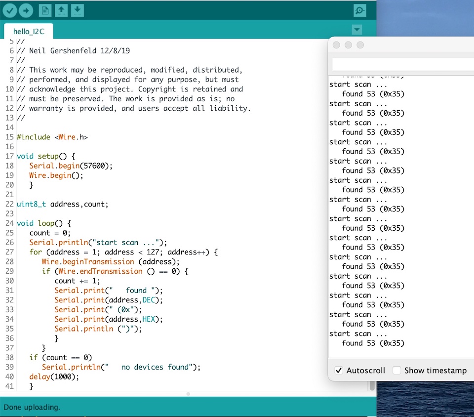
With this set up I first tried the scanner program to check if it worked anyway and which address was used. That was easy enough.
Unfinished Work
Now comes the hard part. To make the SSD1306 work with Arduino some libraries have to be installed. They are readily available in the library manager. That’s not difficult. And then choosing an example sketch should do the trick. Just make sure the address is right and it works. NOT
I first tried the Adafruit libraries and kept running into the error:
In file included from /Users/saco/LasLab/projecten/fabacademy/files/arduino/motor-ctrl/motor_ctrl_display/motor_ctrl_display.ino:14:0:
/Users/saco/LasLab/projecten/fabacademy/files/arduino/libraries/Adafruit_BusIO/Adafruit_I2CRegister.h:7:9:
error: 'Adafruit_BusIO_Register' does not name a type
typedef Adafruit_BusIO_Register Adafruit_I2CRegister;
After that I tried the u8g2 library, but didn’t work either. Now the error when compiling a simple example was that the spi function was not defined and apparently the included spi.h was not found or not accessible or whatever.
This debugging took almost all my time with no positive result so far. So I tried to change my set up and turned to an other display, the HiLetgo 20X4 LCD with I2C Adapter, but that didn’t work either. It even refused to power on, so I stopped there and didn’t finish this assignment.
Retry at the Last Day
I was almost already set to let the whole graduation go (don’t need a diploma anymore at my age ;-)), but finally on the last day of the local evaluation Henk persuaded me to make a last visit to de Waag and try to get an I2C 3D Hall sensor working.
Main Board
I had still my SAMD11C main board with all pin-outs available. I had made a patch on it to get 5 V from USB to the output pin 7 that was until then still unconnected.
The Hall sensor however works on 3.3 V just like the SAMD. Question was: would I replace that patch with one from the regulator or would I keep 5 V and put an extra regulator on the breakout board. Since the regulator is quite small and difficult to connect a wire to it, I decided to use a second regulator.
Breakout Board
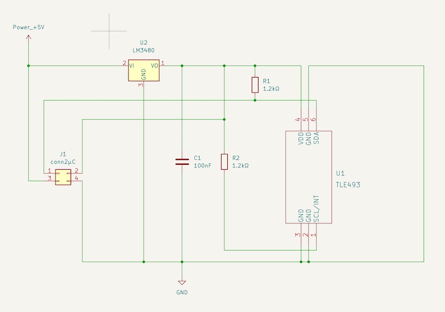
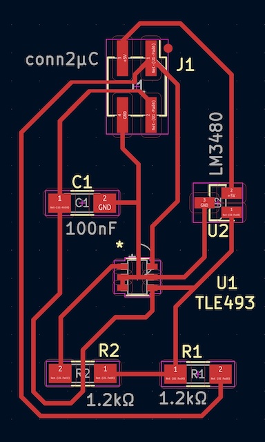
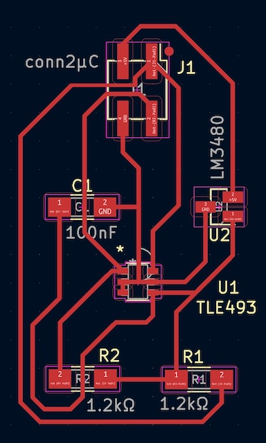
The schematics for the break-out board was based on the application example in the datasheet. Below my first design.
| schematic | lay-out |
|---|---|
 |
 |
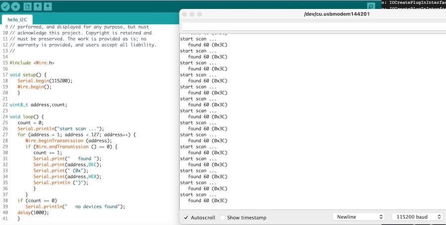
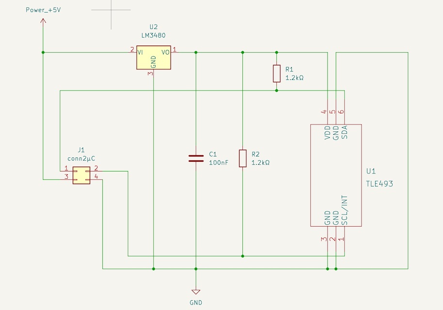
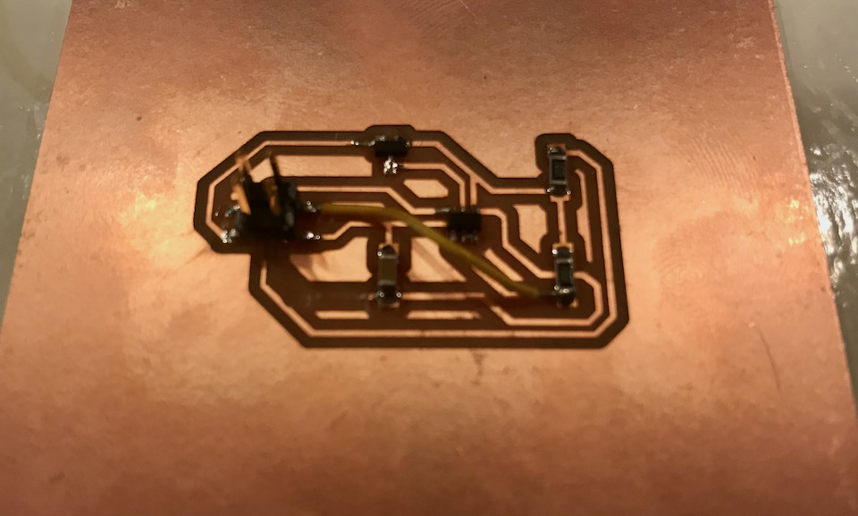
After soldering all components I did the check with the address scan in IDE, but it didn’t work at all. Checking the same scan with the LCD perfectly found the address, so what was wrong here? It turned out I made a mistake in the schematics and connected the SLC to the wrong end of the pull-up resistor, so directly to 3.3V. This is the correct schematic.
| schematic | lay-out |
|---|---|
 |
 |
Making a patch turned out to be easy with just one trace to cut away and one small wire to add.
Programming
After this little debug session, a new attempt of the scan program had a flawless result. The address 0x35 was recognised immediately.
But now I had to get the functional program working. The program I used was a copy from the ATtiny412 from the input devices week. It loaded easy on the SAMD …
    // hall 3D sensor for SAM11D based on:
    // hello.TLE493D.t412.c
    //    TLE493D vector magnetometer tiny412 hello-world
    //
    // Neil Gershenfeld 12/22/21
    //
    // This work may be reproduced, modified, distributed,
    // performed, and displayed for any purpose, but must
    // acknowledge this project. Copyright is retained and
    // must be preserved. The work is provided as is; no
    // warranty is provided, and users accept all liability.

    #include <Wire.h>

    #define address 0x35

    void setup() {
    //
    // start serial and I2C
    //
    Serial.begin(57600);
    Wire.begin();
    Wire.setClock(400000);
    //
    // reset TLE493D
    //
    Wire.beginTransmission(address);
    Wire.write(0xFF);
    Wire.endTransmission();
    Wire.beginTransmission(address);
    Wire.write(0xFF);
    Wire.endTransmission();
    Wire.beginTransmission(address);
    Wire.write(0x00);
    Wire.endTransmission();
    Wire.beginTransmission(address);
    Wire.write(0x00);
    Wire.endTransmission();
    delayMicroseconds(50);
    //
    // configure TLE493D
    //
    Wire.beginTransmission(address);
    Wire.write(0x10);
    Wire.write(0x28);
        // config register 0x10
        // ADC trigger on read after register 0x05
        // short-range sensitivity
    Wire.write(0x15);
        // mode register 0x11
        // 1-byte read protocol
        // interrupt disabled
        // master controlled mode
    Wire.endTransmission();
    }

    void loop() {
    uint8_t v0,v1,v2,v3,v4,v5;
    //
    // read data
    //
    Wire.requestFrom(address,6);
    v0 = Wire.read();
    v1 = Wire.read();
    v2 = Wire.read();
    v3 = Wire.read();
    v4 = Wire.read();
    v5 = Wire.read();
    //
    // send framing
    //
    Serial.write(1);
    Serial.write(2);
    Serial.write(3);
    Serial.write(4);
    //
    // send data
    //
    Serial.write(v0);
    Serial.write(v1);
    Serial.write(v2);
    Serial.write(v3);
    Serial.write(v4);
    Serial.write(v5);
    }
Thanks to the not so very clear documentation of Neil, it took me some time to discover how his example of the TLE with the ATtiny412 worked, especially: what was going to be the graphical output? Well, it’s the python file (obviously …). So I saved the python example and tried to run it on my laptop. But unfortunately that didn’t work. Both python and python3 were not able to run this file (see below).
    saco@SacoBookPro16 network-comm % python hello.TLE493D.t412.py /dev/cu.usbmodem14314401
    Traceback (most recent call last):
    File "hello.TLE493D.t412.py", line 15, in <module>
        import serial
    ImportError: No module named serial
    saco@SacoBookPro16 network-comm % python3 hello.TLE493D.t412.py /dev/cu.usbmodem14314401
    Traceback (most recent call last):
    File "/Users/saco/LasLab/projecten/fabacademy/files/network-comm/hello.TLE493D.t412.py", line 14, in <module>
        from tkinter import *
    File "/usr/local/Cellar/python@3.9/3.9.10/Frameworks/Python.framework/Versions/3.9/lib/python3.9/tkinter/__init__.py", line 37, in <module>
        import _tkinter # If this fails your Python may not be configured for Tk
    ModuleNotFoundError: No module named '_tkinter'
    saco@SacoBookPro16 network-comm %
Luckily Henk was still around, so we connected my boards to his computer. It failed first, but adding the line “import sys” in the py-file did the trick. Yaayyy, it works! Here’s some footage of the sensor with a magnet hovering over it.
Design Files
The program files (.ino and .py) can be found in the block quotes above and in the input devices week links:
And here are schematic and SVG file for the traces. I didn’t make an board outlie, becaause I just used a left over from someone else and used a saw to cut off unwanted parts.