Hello World
During week 4 and 6 we came accross the Hello World board and the tools to prgoram them via FTDI. On this page are my first steps documented in programming thier controllers. The actual assignments were about making these boards, but eventually you want to check if they’re working, so here the programming comes in.
FTDI and SAMD11
In week 4
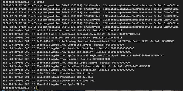
After soldering I tested if the boards were working, below the result of showing the USB list in terminal. For the SAM D there’s a picture with the LED and for the FTDI there’s a short film with the flashing LED.

For the programming during electronics production week I got help from Jonathan because I don’t have any knowledge about that yet. I don’t have a shot of that nor of the command line with the options and parameters he used. I remember he used edbg from the terminal to upload the binary for the bootloader.
At that moment for me it would have been nothing more than carrying out a “monkey trick”. Which is a bit my problem at the start of the fabacademy. The instructors often say: “just proceed with the assignment and later it will all become clear”. Ity doesn’t work that way for me. I want to understand what I’m doing before taking action. It would have helped me a lot if there was a good overview of how microcontrollers work in general and the functions of bootloaders and which options are available to get them in. Same for programming in general. It took me to week 11 to finally learn that once the bootloader is on, for the SAMD you don’t need a programmer board. :-P
Hello World Board
In week 6 we redesigned the Hello World board see the E-design page about that. When I was finished, I had to program it to check if it was working. We made the FTDI board already in week 4 and also the adapter board for converting the Rx - Tx signal to the FTDI serial input port.
The start got me annoyed a bit already, because I couldn’e understand either the instructions or the video from Niel. It turned out that we had to install the Arduino app and apparently I missed that part. After installing this it made more sense though the difference between the version Niel showed - Arduino IDE 2.0 - and the version we use - Arduino 1.18 was confusing.
The standard libraries didn’t include the ATtiny412, so I had to include a special library for that too by adding “http://drazzy.com/package_drazzy.com_index.json” to the line “Additional Board Managers” in the “Preferences”. Important note: it failed first, because it doesn’t use a secured connection, so “https” didn’t work.
But then an unsovable problem occurred: the board was visible when I listed the USB devices connected, but Arduino didn’t see its port. Turning to Henk learned that it did work on his computer and programming was easy.
But eventually he discovered there’s a problem when using FTDI on Macs with OSX 11.6 (Big Sur) as documented on hackaday.
Only solution is to use the SAMD11 version of the FTDI programmer, the only board I didn’t make during the electronics production week. :-P
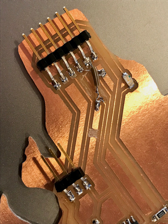
After programming we connected it with the SAMD board, to try the echo program. This still didn’t function. The hypothesis is that the Rx and Tx have to be switched, because the Tx will have to connect to the Rx of the other controller and most likely it tried to talk to its Tx. Henk designed a small board that switches them around, and later I made patch to switch them around.
Programming ATtiny412
After assembling the programmer board I started programming the board with the ATtiny412 from the E-design week. In the Arduino IDE the board can be selected in the megaTinyCore section of the board manager.
Programmer Problems
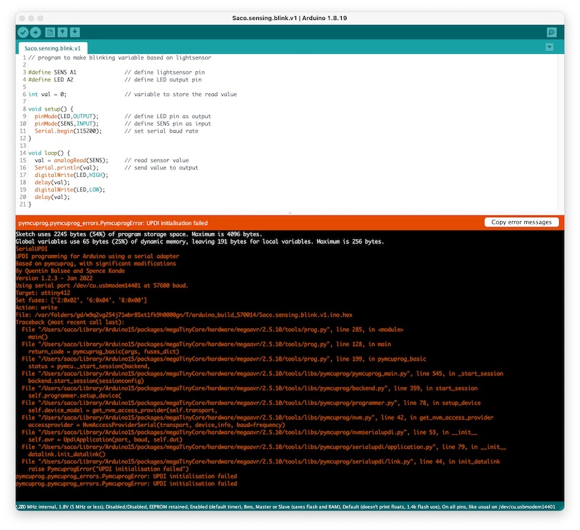
Unfortunately it didn’t work. Somehow the programmer was not able to initialise UPDI.
It took a lot of retries and help from Henk to fix this problem. First Henk tried to correct the serial communication and this worked for a short while. After programming a couple of times the error came back. In the end after flashing a new bootloader the problem was solved. We still don’t know what the problem was and this issue also occurred with others.
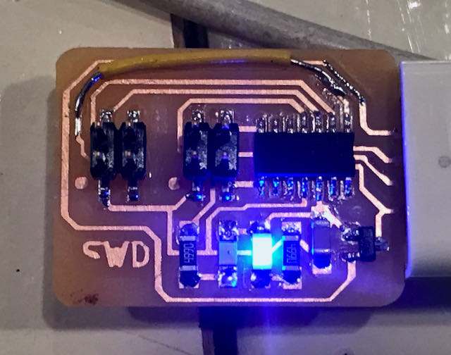
My plan for this first programming steps was to make a blinking LED of which the blinking frequency depends on the amount of light received by the photo transistor. Below a short movie with the blinking LED and the switch states of it on the serial monitor.
Program Principle
To start my programming I made up an idea how it should work in words:
- read the photosensor
- if there is no light:
- switch off the LED
- else:
- set the delay time based on the light value
- make the LED switch on and of with the delay in between
Datasheet
To be able to program the board, I first had a look at the datasheet. The first information needed is the pin configuration that determines the pin definitions at the beginning of the program. Secondly the resolution of the analogue pins is needed to determine the trigger values I want for setting the brightness of the LED.
Final Program
The latest version of the program below also maps the value of the light conditions to the full range of 10 bit. This allows me to get a better response when dimming the light with my hand above the sensor. If the sensor is covered completely the LED switches off.
#define SENS A1               // define lightsensor pin
#define LED A2                // define LED output pin
#define BUTT A3               // define button pin

int lightval = 0;             // variable to store the read value
int lightmap = 0;             // variable to store mapped light value
int lightmin = 850;           // variable to store lowest light value
int lightmax = 1023;          // variable to store highest light value
int buttval = 0;              // variable to store the button value

void setup() {
  pinMode(LED, OUTPUT);       // define LED pin as output
  pinMode(SENS, INPUT);       // define SENS pin as input
  pinMode(BUTT, INPUT_PULLUP); // define BUTT pin as input
  Serial.begin(115200);       // set serial baud rate
}

void loop() {
  lightval = analogRead(SENS);              // read sensor value
  lightmap = map(lightval, lightmin, lightmax, 1, 1023);
  lightmap = constrain(lightmap, 1, 1023);
                                            // map sensor value to output value with constraints
  buttval = digitalRead(BUTT);              // read buuton value
  Serial.println(lightval);

  if (lightmap > 900) {
    Serial.println(lightmap);               // print mapped value light sensor
    digitalWrite(LED, LOW);                 // switch off LED
    delay(lightmap);                        // delay with value of light sensor (1 ~ 1023)
  }
  else {
    Serial.println(lightmap);               // print mapped value light sensor
    digitalWrite(LED, HIGH);                // switch on LED
    delay(lightmap);                        // delay with value of light sensor (1 ~ 1023)
    digitalWrite(LED, LOW);                 // switch off LED
    delay(500);                             // delay with value of light sensor (1 ~ 1023)
  }
}
What I wanted to do next is to use the button to initialise the calibration for the mapping. Because the programmer board problem I wasn’t able to finish that yet. During the regional review a good suggestion was given to use the min and max functions for that.