Week 7
Computer-Controlled Machining
Organizing
checklist
| group assignments | — |
|---|---|
| Complete your lab’s safety training | |
| Test runout, alignment, fixturing, speeds, feeds, materials and toolpaths for your machine | |
| Document your work to the group work page and reflect on your individual page what you learned |
| individual assignments | — |
|---|---|
| Make (design+mill+assemble) something big |
This will be my first time designing and making something myself on a big CNC machine. I have watched a college working with the machine not so long ago and so I know a little bit about the workflow of the process but I have lots to learn this week!
General info big CNC
I combined notes from Neils lecture and the wokrshop at Waag from Saco and Henk for the following info about working with big CNC milling machine.
Tips
- Do prototyping before making the big thing. For example with cardboard or with the lasercutter.
- Fusion360 has the best integrated cad to cam, it generates the toolpath and you can view it in the program.
- Take a look at Japanese woodworking joints for inspiration joints.
- Use a service milling bit to flatten the sacrificial layer to make sure your material is level.
- Be aware that you need to choose to Z level on the sacrificial layer or on your material.
Materials for cnc
- Basics like: wood, HDPE, foam
- Garolite: based on cotton
- Hilite: aluminum top nice for bending
- Wacky wood : good for bending / curving
Milling bits
- carbide metal: though metal
- invest a little bit more in buying a coated bit: coating bits are more though
- end mill: look at the flutes (number, up or down, double) I like this tutorial for understanding the differences in bits as a beginner.
- tapered mills for smooth finnish, end mills make a staircase finnish.
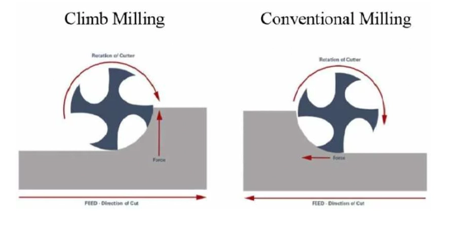
Cutting direction The direction of the movement of the milling bit has huge influence on the product.
- climbe milling - If you use a hand mill never conventional always climb! the direction of the movement of the mill eats away the wood from the top, used for finish cut. Larger forces but cleaner cuts.
- conventional milling - biting in the stock is pulling the tool in the stock, Less forces but rougher cuts.
Speeds and feeds speed raters:
- to slow -> results in waisting time and can chip off peaces of the material
- to fast -> makes terrible noise overheating and can break tool
Try to find a good spot in between.
- cut depth: the diameter of the tool is a good scale for the max depth of one pas.
- step over: multiple passes (step -over) 50 percent overlap so for 8 mm milling bitt it will be: (diameter/2) = 4 mm step over
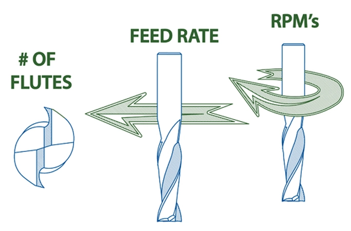
- Spindle speed : spindle RPM
- Cutting speed: one round of one flute so this depends on the number of flutes. In mm/min
- Feed rate : X end Y direction in mm/min
- Chipload : the thickness of one chip depends on cutting speed and feed rate speed
Fixturing Extremely important since you working with great forces. You can use nuts and bolts, clamps or a vacuum table. Always use a sacrificial layer underneath your stock because you will mill though material and don’t want to damage the machine.
Toolpaths
- toolkerf use an offset for the tool diameter
- Runout (quality of the tool) kerf will be slightly larger because of the spinning motion
- The more directions you are going to mill from the more complex the toolpath.
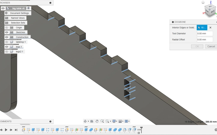
- T bones: go a bit further in the inner corners so things will fit! and you don’t have an unwanted fillet in the corners. Left side of the picture
- Dog bones : same thing as T bones but different orientation. Right side of the picture

- Taps: small taps so the work will stay in place, remove later.
- Onion skinning: thin layer on the bottom so the work will stay in place.
- Nesting for optimal nesting use nesting software like Deepnest
- For bending wood leave around 3 mm from below unmilled.
- We will mill 2 1/2 D meaning X, Y every location Z only from the top size
Safety
Start with
- investigating risks
- remove risks
- reduce risks
- personal protection for what you can’t fix
Watch out for:
- Splinters : wear gloves
- Burns : when things spin at high speed is becomes hot
- Impact : flying parts
- Fires : with wrong settings particles can get so hot the dust collector started a fire inside, also when you run into a screw
- Tools break : wear safety glasses, eye protection
- Clothes and hair : nothing loose
- Look listen and smell : pay attention with your eyes nose and ears
- Never reach into a powered tool : you want to keep your fingers
- Emergency button : know where it is before you start!
- Assistance : never work alone in case of emergency
- Mood : don’t do it when your mad or tired not rushing, be fully present
Individual assignment
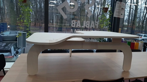
For my individual assignment I want to design and mill a coffee table for near the couch at my apartment. I want to make something I can use when it’s finished and we are currently missing a good table. I use 18 mm poplar plywood for the project from this supplier
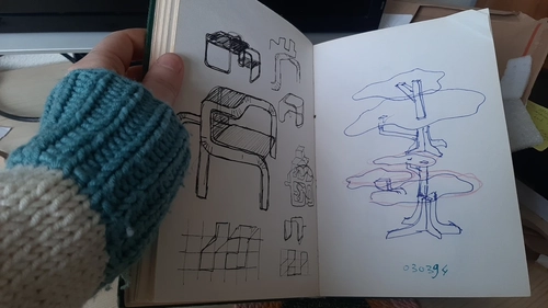
For the designing process I found inspiration from the samples in the lecture. I like the idea of making use as much as possible of the wooden plate material.
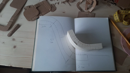
We saw a chair that was made from one plate of wood for example. I want to do something with this concept and I also like the bending of wood by milling away slots. To get to an design I start with sketching some ideas from my head and I adjust is so the wood will only bended in one direction. 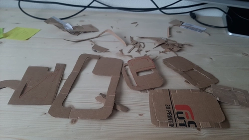
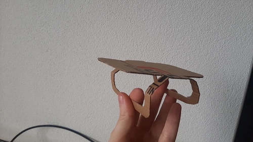 I use cardboard to make different cuts and little prototypes and I especially like one design with a floating table top.
 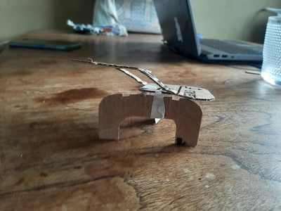 I decide to stick with it and start with making a bending test and start the design process in Fusion360.
Machine
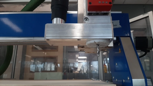
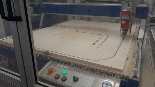
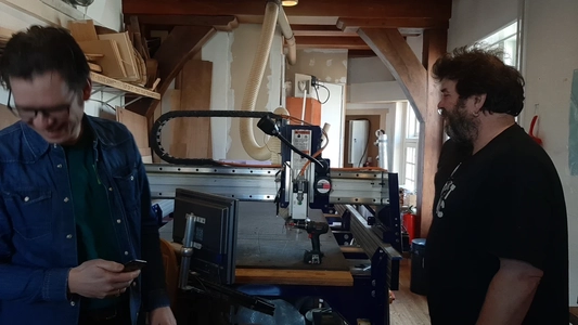
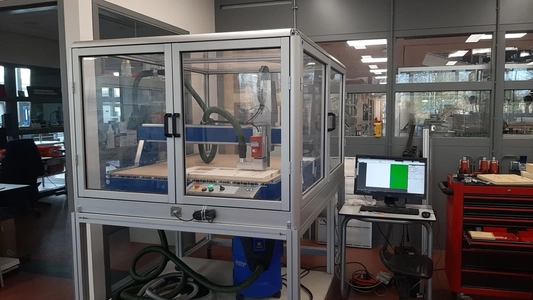 At Waag we worked with their Shopbot I will tell about later but for my individual assignment I used the Haase AL1290 CNC machine elte TMPE29/2 400 Hz 0.8 kW from the University I work at.
This machine has a range of 1250 by 900 mm and a spindle with 0 to 10 speeds stands.
The spindle should be able to get to a maximum of 24 000 RPM.
So it should be around 16000 per number. And stand 1 should be 8000
At Waag we worked with their Shopbot I will tell about later but for my individual assignment I used the Haase AL1290 CNC machine elte TMPE29/2 400 Hz 0.8 kW from the University I work at.
This machine has a range of 1250 by 900 mm and a spindle with 0 to 10 speeds stands.
The spindle should be able to get to a maximum of 24 000 RPM.
So it should be around 16000 per number. And stand 1 should be 8000
Stand - RPM
- 0 - 6000
- 1 - 7.800
- 2 - 9.600
- 3 - 11.400
- 4 - 13.200
- 5 - 15.000
- 6 - 16.800
- 7- 18.600
- 8 - 20.400
- 9 - 22.200
- 10 - 24.000
I mostly used speed 6 for milling which should be around 17.600 RPM. For drilling I used speed 1 which should be around 8.000 RPM
CAD
Fusion360
- start with sketching the outline of the table and give it the right dimension.
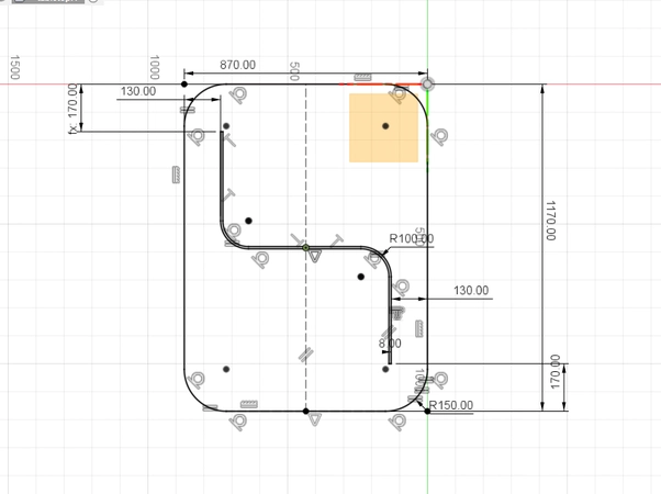
- extrude it using the woodthickness parameter you create.
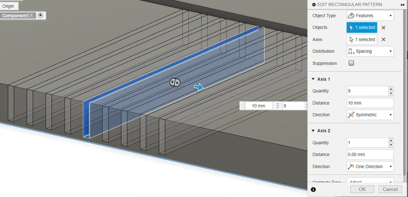
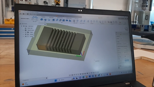
- Design one slot and cut extrude this slot, make a rectangular pattern from this feature to create the bending pattern. I use the taperedbit parameter (my tool is 3.175 mm in width) for the slot width. And pretend is will be a flat end mill in the simulation but I will cut it with a tapered bit to create v shaped cuts for seamless bends. You can read about it later.
- create a new component for the first leg on a reference plane in a 90 degrees angle of the tabletop and use projection: shortcut p to project the outer shapes of the table as a guide line. Create the sketch of the legs and use the extrusion for the thickness
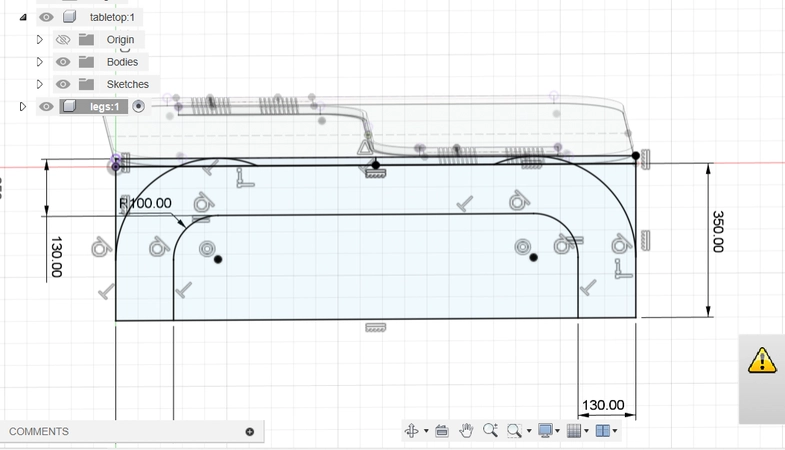
- Same thing for the second leg. Once all the components are in place I use the combine feature and select a target and tool body use the cut operation and select keep tools. The overlapping joints will now be cut out of the target body.
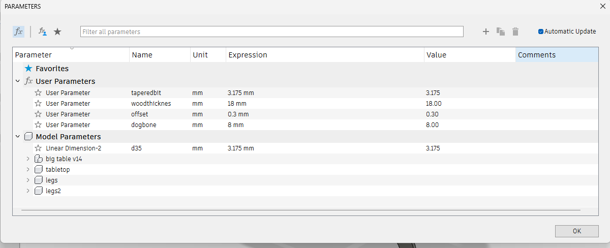
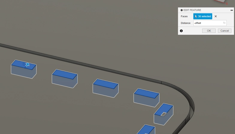
- I now create the offset for the joints in the pockets by using the - offset parameter which gives it an offset of minus 0.3 mm on every side. This turned out to need some sanding afterwards so next time I would go for -0.4 mm
- I used this dogbone plug-in for Fuison360 but the next time I will draw them myself to have a more generative design. So I actually don’t recommend it it makes lots on features packed in a group and in not easy to change afterwards. But to work with it you simply select the corners and set the diameter of the tool.
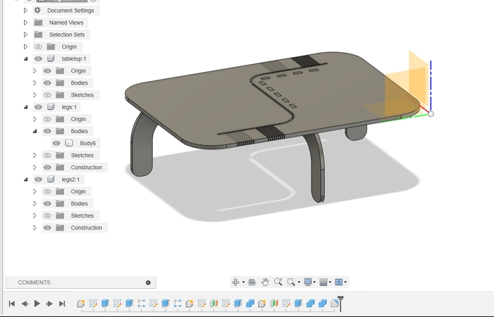
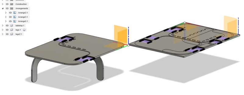
- I create a new component and make it the size of my wooden stock. I will use this to arrange my models on for milling using the modify -> arrange tool . I end up with 3 different arranges. One for the topside of the tabletop on for the bottomside of the tabletop (there is a flip top layer button to flip the model) because I need to mill the bending pattern on both sides, and a third arrange for the two legs. I can put the sight of the arranges on and of when clicking on the eye in my design tree so it will be easy to work with for me.
CAM
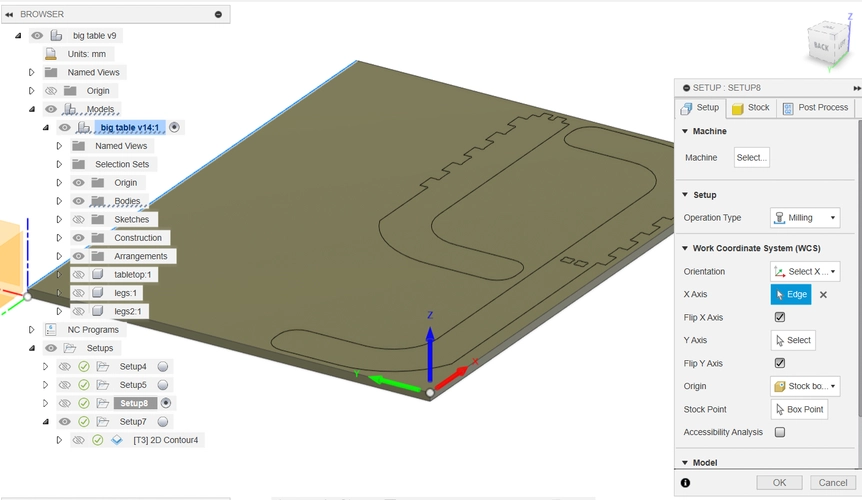
Create Set-up
- Go to the Manufacture environment and start with making a new set-up. In the toolbar -> Set-up -> New set-up

- Don’t select a machine because the machine is not inside Fusion I leave it empty now.
- Start with select your stock first, in this case I already made a body of the size of the stock so I select the stock by selecting the body.
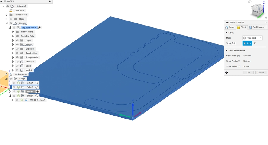
- select the models you want to CNC. I used the arrange function to place the models flat on my stock and select in this sample both the table legs I want to CNC
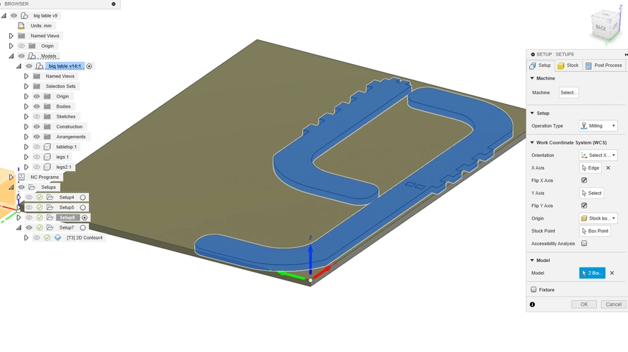
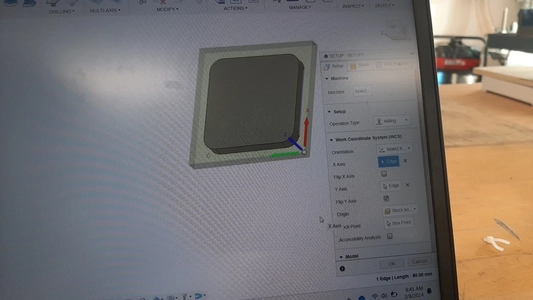
- select the origin, it’s very important that your X Y en Z axis are in the right direction for the movement of the head to be in the right direction when you start milling.
I choose to level the milling bit on top of my stock so I will set it’s origin on top as well.
For this I use the select X and Y axis and select a stock point as a third reference.
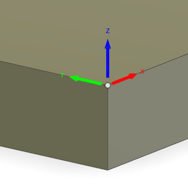 If the axis are not in the right direction you can use the flip buttons to flip them around. It takes some practice at first to get it right. Pay attention that X needs to be the short axis and Y the long one. Here you can find a sample:
I make three new set-ups for my three arranges starting with the top on the table, then the bottom and then the legs.
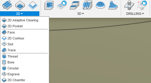
Create toolpaths
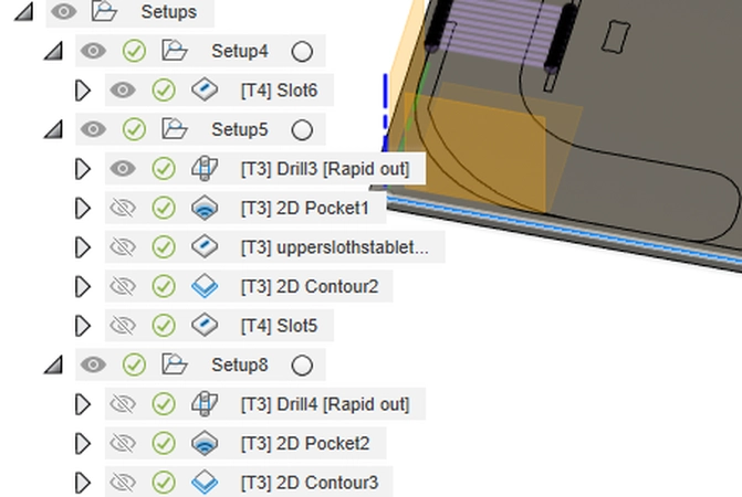
For my final project I used the following toolpaths:
 Set-up one tabletop from the top
- Drill - for drilling the dogbones
- 2D pocket - milling the join pockets
- Slot - milling the stipe in the middle of the tabletop
- 2D contour - milling the outer contour for the tabletop
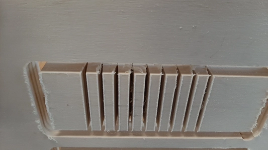
- Slot - milling the bending pattern (3.175 mm tapered ballnose bit)
Set-up two tabletop from below
- Slot - milling the bending pattern (3.175 mm tapered ballnose bit)
Set up three table legs
- Drill - for drilling the dogbones
- 2D pocket - milling the join pockets
- 2D contour - milling the outer contour for the table legs
 When creating a new toolpath in Fusion I used this workflow:
- First Tab: Tool
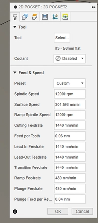
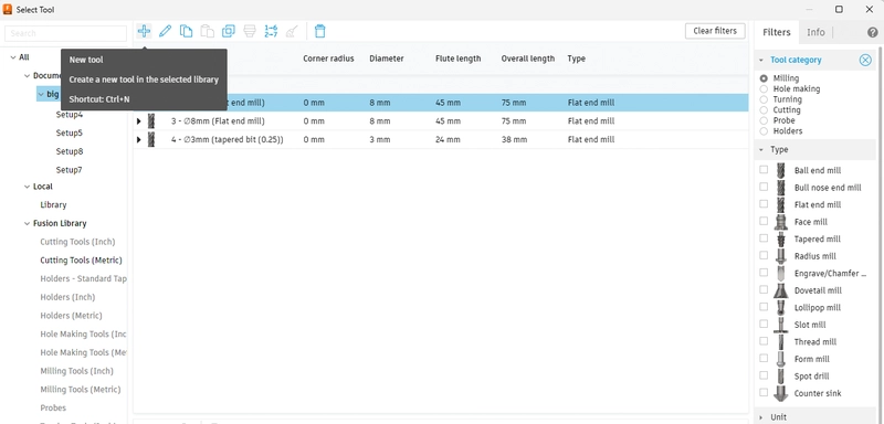
- Start with selecting the right tool fot the path. Tools I used for my project:
- 8 mm end mill with up and down cut amazon link
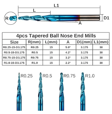
- 3.175 mm tapered ballnose bit for milling the bending pattern amazon link
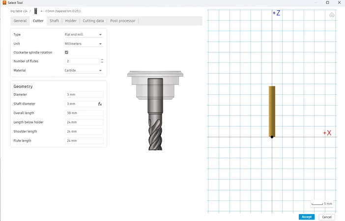
- I add these mills by pressing the plus sign and putting in the right settings for each tool. I ordered my tools from Amazon and fill in the information from here.
 Paying extra attention to tool diameter, cutting length and numbers of flutes. In the preview you can see how the milling bit looks.
- I follow the advice from my college Niels and put the chipload to 0.06 mm to calculate the feed rate I play with the RMP for creating pockets I use 12000 RPM with makes the feed rate 1440 mm/min
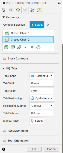
- Second tab: Geometry
- select the changes you want to mill towards from below.
- when you are working on contours make sure to add tabs I add tabs from 10 mm width 2 mm thickness and 100 mm spacing between and generated them.
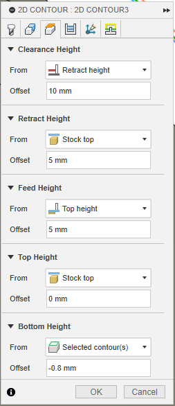
- Third tab: Heights
- offset 5 mm above the stock when traveling
- because I didn’t surface (mill a nice layer away to level it) my sacrificial layer I used the model bottom offset of minus - 0.8 mm to make sure I mill trough the plate material and a little bit into the sacrificial layer.
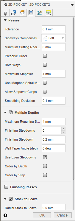
- Forth tab: Passes
- It’s important to select multiple passes so you wont go through the material at once, since my material is 18 mm in thickness. I used half on the diameter of the tool for one pass to be on the safe side so for my 8 mm endmill i used 4 mm for the maximum roughing stepdown. For the 3 mm tapered bil I used 1,5 mm because of it’s tiny 0.25 ballnose I wanted to be extra careful.
- It you make pockets make sure to check the Maximum stepover. I again used half on the tool diameter. If you create pockets that wont go all the way though it’s a good thing to use a little bit more so you don’t create lines in your model so for example 4.1
- Underneath passes select sideways compensations: climb milling left or conventional milling right I selected left for climb milling
- Fifth tab: Multi Axis
- Didn’t use this tab in this project the machine type is a 3-axis machine
- Sixth tab: Linking
- Here you can change the leads and transitions for me the most important thing here is the Ramp type. Im my project I used the Plunge type that plunges in in the stock from the top.
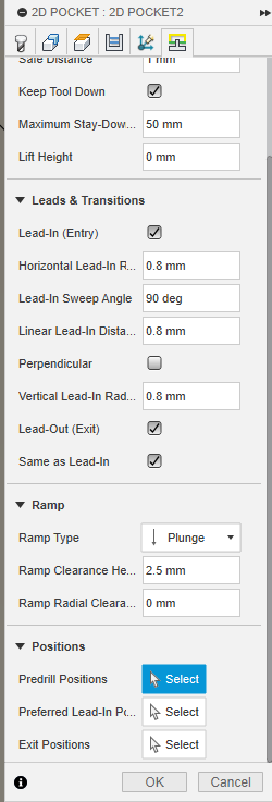
If you have all the settings correct press OK and generate the toolpath. check out the preview for the toolpath in the Simulate function go to Action -> simulate. I like to watch it from the top and the side from the side you can see if the tool will go trough the material because I gave it a -0.8 mm offset on the bottom. Here you see an sample:
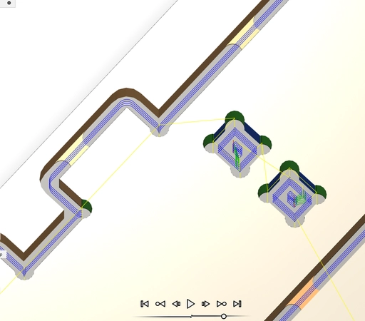 Always first simulate the toolpath
To export the toolpath select the toolpath or the set-up and go to Action -> Post process
In the first tab select the post processor CNC graf7 I got this processor file from my college Niels who made this set-up for the Haase AL1290 machine! Super nice!
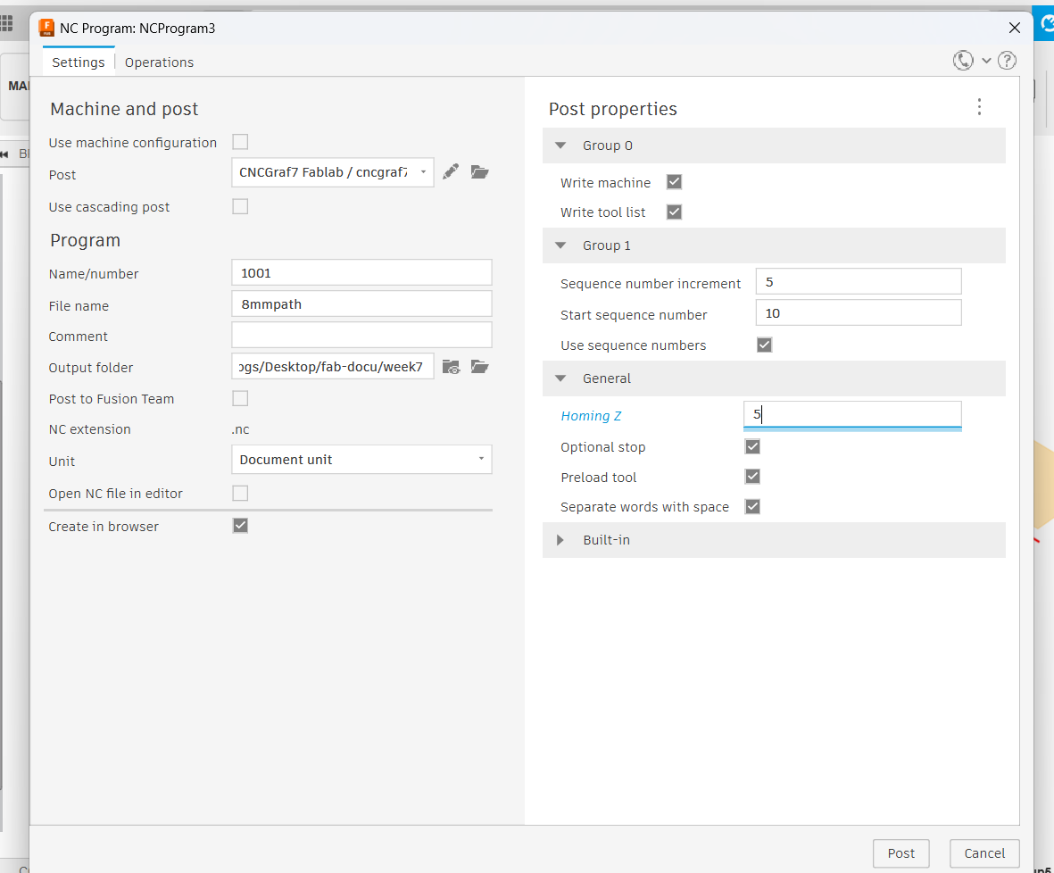 Homing Z I put to 5mm this will add 5 mm extra upp for traveling
Name your file and choose the output folder.
Homing Z I put to 5mm this will add 5 mm extra upp for traveling
Name your file and choose the output folder.
In the second tab select the paths you want to process. I put everything with the same toolbit together in one file in the right order, so first milling the pockets and slots and then the outline.
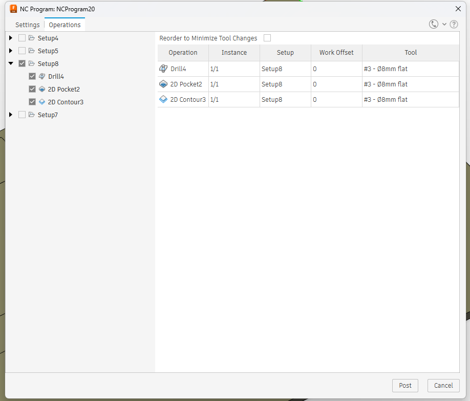
Now click on post it will generate an .nc file that you need to tranfer via a USB stick to the computer next to the CNC milling machine.
Test runs
 I first do test runs on the machine with a simple 2D contour of a box and a slot with the 8 mm endmill.
I test the offset and also the feedrate.
After this I test the slots with the tapered bit to test the woodbending.
I first do test runs on the machine with a simple 2D contour of a box and a slot with the 8 mm endmill.
I test the offset and also the feedrate.
After this I test the slots with the tapered bit to test the woodbending.
Feed rate For the first try for the 2D contour I use the following settings: Settings in Fusion:
- speeds 8000
- feed per tooth 0.06
- calculated feed rate 960 mm/min Spindle speed: I put the machine on stand 6 with is around 15000 RPM
For the second try for the 2D contour I use the following settings: Settings in Fusion:
- speed 12000
- feed per tooth 0.06 mm
- calculated feed rate 1440 mm/min Spindle speed: I put the machine on stand 6 with is around 15000 RPM
- I conclude that the chips are less powdery in the second run and the feed rate is faster so I liked the second one better for making contours and passes. But both look great actually i’m very happy with the results.
offset
I mill two pockets the first pocket I put 0 mm offset and the second on 1 mm so 0.5 mm on both sides
The first one doesn’t fit and the second one fits like a puzzle a bit wide. So for my table I decide to go somewhere in the middle and choose 0.3 mm offset on every side.
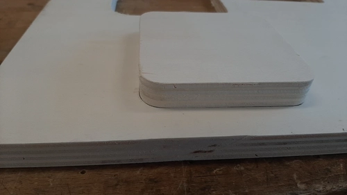
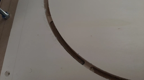
wood bending tests
 Test one
for the first test I let the milling paths stop at 3 mm from the bottom in my design
I use a 3 mm tapered ballnose 0.25 mm bit with 2 flutes
1,5 mm multiple passes cutting depth
Settings in Fusion:
RMP 5.000 plus minus stand 6
feed per tooth 0.06 mm
calculated feed rate 600 mm/min
Test one
for the first test I let the milling paths stop at 3 mm from the bottom in my design
I use a 3 mm tapered ballnose 0.25 mm bit with 2 flutes
1,5 mm multiple passes cutting depth
Settings in Fusion:
RMP 5.000 plus minus stand 6
feed per tooth 0.06 mm
calculated feed rate 600 mm/min
Spindle speed:
I put the machine on stand 6 with is around 15000 RPM
 The bending if very hard i can see that the material needs a bit more deeper cut and I break the wood while playing with it. I Adjust the distance between the cuts from 7 mm apart to 10 mm apart and change the depth of the cut 1 mm deeper.
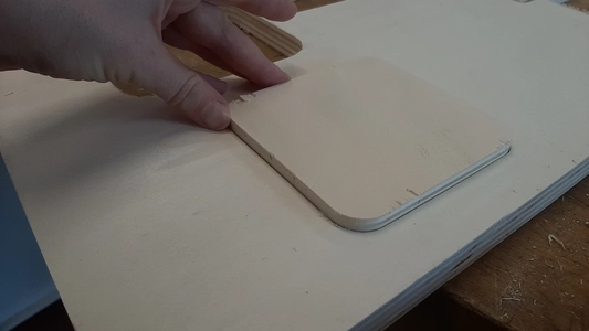
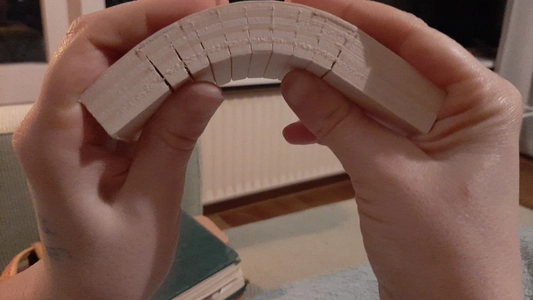
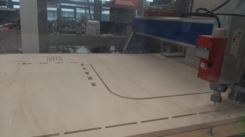
Test two
for the second test I let the milling paths stop at 2 mm from the bottom in my design
I use a 3 mm tapered ballnose 0.25 mm bit with 2 flutes
3 mm tapered ballnose 0.25 mm bit. 2 flutes
1,5 mm multiple passes cutting depth
Settings in Fusion:
RMP 5.000 plus minus stand 6
feed per tooth 0.06 mm
calculated feed rate 600 mm/min
Spindle speed:
I put the machine on stand 6 with is around 15000 RPM
 The result looks really nice I will try to bend the wood at home using an iron with steam function. But It’s already bends way better than my first try. I think I have al the settings figured out for my big project!
Settings for table project
2D pocket and contours 8 mm end mill
- feed rate 1440 mm/min
- spindle speed 15000 RPM
- 4 mm cut depth per pass
- stepover 4 mm
- plunge
- Bottom height -0.8 mm
Slot
- 8 mm end mill
- feed rate 960 mm/min
- spindle speed 15000 RPM
- 4 mm cut depth per pass
- plunge
- Bottom height -0.8 mm
Bend slots
- 3 mm tapered mill 0.25 mm ball nose
- feed rate 600 mm/min
- spindle speed 15000 RPM
- 1,5 mm cut depth per pass
- plunge
- Bottom height -0.5 mm
Drill
- 8 mm wood drill
- plunge speed 333 mm/min
- spindle speed 1250 RPM
- 1,5 mm cut depth per pass
- Bottom height - 4 mm
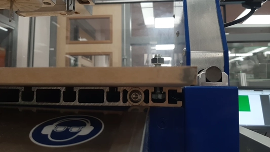
Machine prep
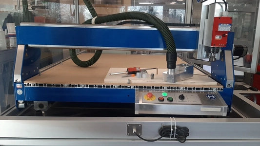
Fixturing
Because I wan’t to use the maximum bed volume of our machine I have to make a sacrificial layer and can’t use the clams we usually for clamping smaller peaces of wood. I use two MDF plates and use the table saw to get it the right size. I measure the tunnels on the CNC bed and align the drilling holes of the left and right size of the machine on top of them. I drill one more hole an the front plate and one at the back plate.
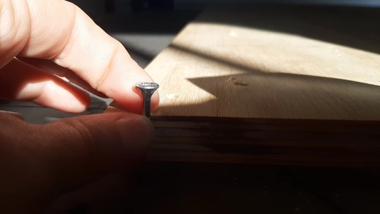
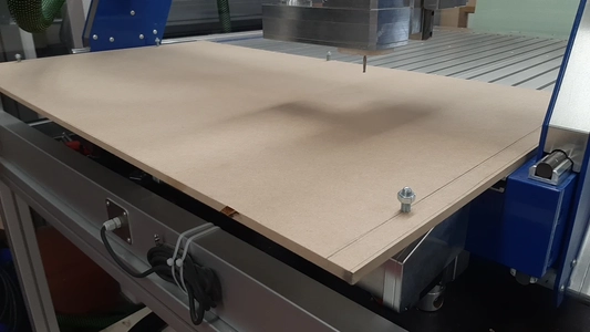 I use nuts and bolts to fasten the plate and the nuts fits perfectly in the tunnels of the bed of the CNC. From the top I fasten the nuts and check if everything is straight and tight. Al my nuts and bolts are outsize of the working area of the CNC so it can never hit it with it’s milling bit. I’m happy about my set-up. I will use parker screws to fasten my material on top of it. I used 9 mm MDF because we had it laying around. Next time i would prefer a thicker sacrificial layer so you can use longer screws.
I used the nuts with small plates of metal to fasten the material together with parker screws on all the sides. aligning my wood against the bolts and nuts make sure it’s nice and tight.
I use nuts and bolts to fasten the plate and the nuts fits perfectly in the tunnels of the bed of the CNC. From the top I fasten the nuts and check if everything is straight and tight. Al my nuts and bolts are outsize of the working area of the CNC so it can never hit it with it’s milling bit. I’m happy about my set-up. I will use parker screws to fasten my material on top of it. I used 9 mm MDF because we had it laying around. Next time i would prefer a thicker sacrificial layer so you can use longer screws.
I used the nuts with small plates of metal to fasten the material together with parker screws on all the sides. aligning my wood against the bolts and nuts make sure it’s nice and tight.
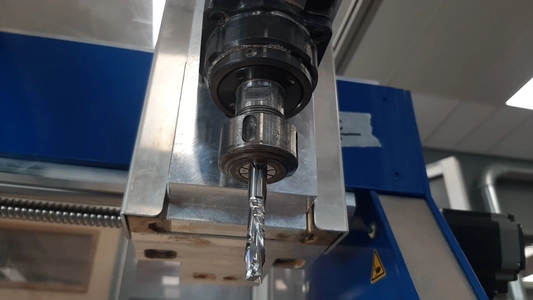
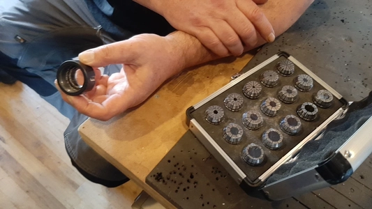
Changing milling bits
- Don’t forget to wright down al your 0 coordinates before starting so you can always go back to it after changing changing bits for example just to be sure.
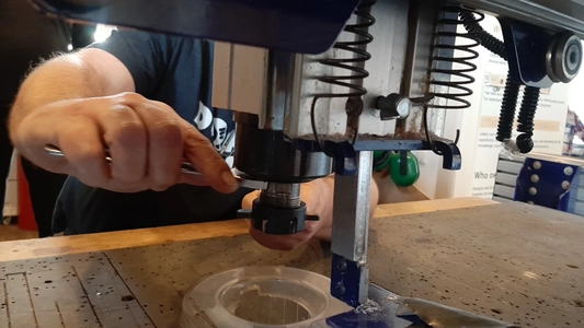
- Move the Z up and unscrew the crew on the picture to remove the block for the vacuum extracter.
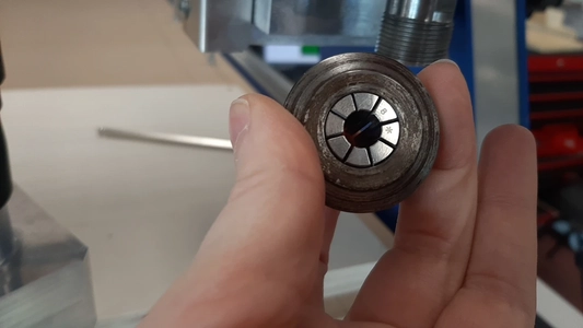
- Unscrew the Collet using a special wrench and a normal one. Both together can be used to unscrew and fasten the collet.
- Find the right collet for you milling bit and put the collet back in the nut now fasten is loosely and put the milling bit inside the collet. Fasten the collet tightly again using the two wrenches. Make sure to test if the bit it turning straight down and not in a small angle by spinning it with your hand.
- Now lower the Z on the material where you want to level it. For the last steps go slowly with micro stepping when bit touched the material go one step back up and it’s leveled. It helps to spin the milling bit a little with your hands, but watch out the bits are very sharp so don’t touch the flutes.
- Don’t forget to set the Z to 0 in this spot only the Z so not the X and Y coordinates when your working on the same side with a different bit.
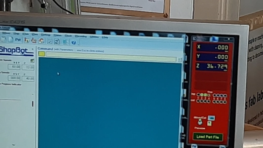
CNC Graf pro
- Start with homing the machine selecting the home button
- Move the axes in the menu on the right side. for micro stepping select step by step
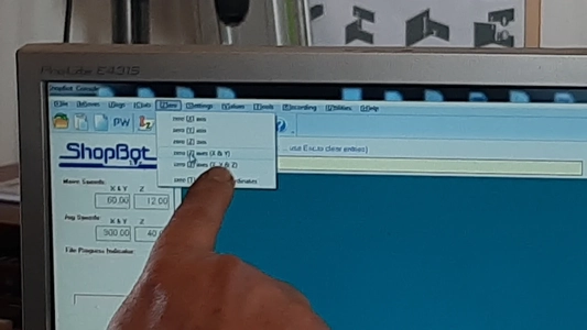
- On the top you can find buttons for setting the 0 coordinates for Z, X and Y axes. I mostly use the set X and Y axis to 0 and the set Z axes to 0 separately. Always first home your machine before setting in new 0 coordinates.
- To open a file go to file -> open -> select your file and look at the preview if your project fits inside the bed of the machine. If it doesn’t you probably need to change the origin X, Y, Z coordinates in your CAM
- Is you want to do a safe test run put the Z axis up a bit (like 5 cm) and makes this the nes 0 coordinates. Don’t forget to write down your actual 0 coordinates before doing this otherwise you need to Z level again. And start the machine it will now make it’s pass in the air.
 First go to the position where you want to set the new 0 coordinates and then import the file this way the origin of the file will be places were the head off the machine is positioned so your project won’t be out of the reached area. Think about how you want to align your project if you need to mill on two sides before you start and chose one point that is visible on both sides to level the head of the machine on top of.
The actual making
Wood bending test
I got the idea from this tutorial about making a floating shelve. Using a tapered bit and using the iron.
materials you need:
iron
wood glued
sandpaper
material to keep the shape like clamps, rope or tape
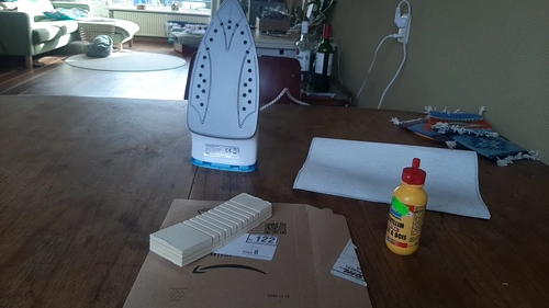
I start with sanding the creases to make sure there won’t be any chips of wood left in there to make sure my wood will bend all the way.
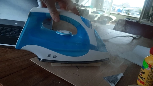
I fill the iron with water for the steam function and heat it up to start steaming and ironing my wood. I test the bending and immediately feel a big difference. I don’t feel much resistance and it bends easily if feels less likely to crack. Yeay!
I add the wood glue in the creases and bend the wood a bit in the other direction so the glue gets in the crease. I use a bit ao paper to push it further and add a second layer of glue.
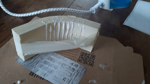
I bend the wood again and notice i used a bit too much glue. I use the tape to fasten the position and use a peace of cardboard to scrape the extra glue of the wood. I leave my wood to dry.
Milling and assembling
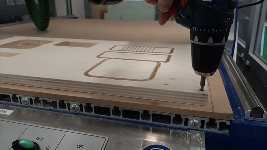
Lets start with that this was an extremely chaotic day it’s been a way longer day then anticipated because a lot of things took more time. I want to start with saying my colleges and especially Niels helped me out a lot today with everything really. It’s super nice to double check each other making sure you don’t mess anything up and to start getting to know this machine better and better. Also to help me think how to fix things and I had quite some troubles on the way.
In my preview you can see that the circles of my dogbones are not as sharp and tight in the corner as I intended it, I don’t know if I will get a good 90 degree angle thath why I decided to drill the holes first and then pocket the slots. When I start the drilling part of the dogbones (I did not test it) with the 8 mm end mill bit who has a up and down cut, it smoked and the wood got burned, we lowered the RPM to the lowest possible but still has the same problem, we used the plunge settings. I don’t think this milling bit is up for it so I end up changing the end mill for a normal drilling tool of 8 mm. This worked very nice but it took a lot of time remaking the toolpaths because I now need to change tools in this job and also loosen and fasten the collet to change the tools, level the Z again and again and again and change the RPM to the lowest speed. And need to remind my self to change it to stand 6 again later.
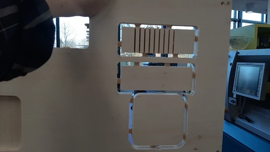
 Next big issue came from making the bendpattern at the back side so flipping my work piece. Because it’s not milled in the center of the wood we cant just flip it around. The plan is to use on of the holes of the dogbone to level but when we checked if the wood was perpendicular it wasn’t… So new plan is to draw the tabs of the other contour on the sacrificial layer and try to move the plate around that it fits those drawings as best as possible.
 This was a pain in the ass and when I wanted to drill the bend pattern I was 4 mm off from the side, so I leveled my Y 4 mm to the left and started again. Now it looks nice but it would have saved tons of time when the wood was perpendicular or when we thought of a smarter way to flip the peace before starting.
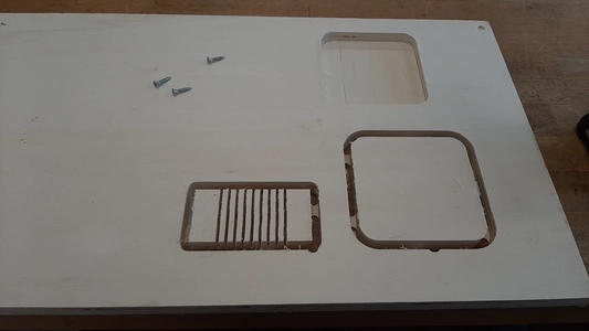
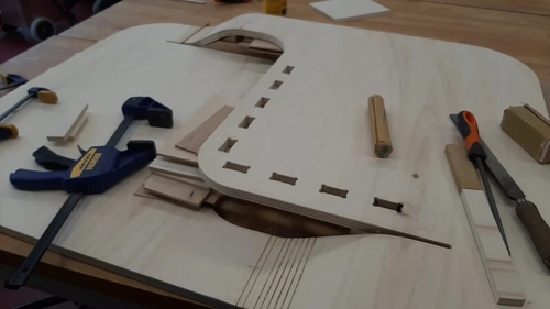
 The hard part, the table top is now done. The good thing about this hole process is that I’m getting really comfortable with leveling this machine and changing tools.
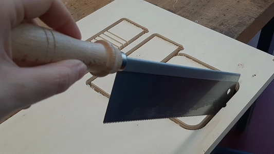
When my design is finished I cut it out with a handsaw. the table already starts to bend so I’m very exited at this moment. We slowly put the tabletop on another table and try to bend it a little bit, I should have known better to not do this but first steam it, but I didn’t and one side snapped. AHHHHHGGH!!! What a shame!
The hard part, the table top is now done. The good thing about this hole process is that I’m getting really comfortable with leveling this machine and changing tools.
When my design is finished I cut it out with a handsaw. the table already starts to bend so I’m very exited at this moment. We slowly put the tabletop on another table and try to bend it a little bit, I should have known better to not do this but first steam it, but I didn’t and one side snapped. AHHHHHGGH!!! What a shame!
 I decide to first start the last milling job of the legs of the table and will later deal with the break. First drill again and then mill. It all went fine. Back to the table. I steamed it slowly bend it using tools underneath to support the tabletop. I mix glue and sawdust for fixing the break. I put the mixture in the bend feature glueing the broken side and the not broken side. I notice that on the broken side the bit is almost through the wood so that’s why it snapped zo easily. It’s probably because the wood is a bit crooked and the sacrificial layer is not surfaced.. Also my design choices where a bit optimistic I think with the bending and the floating part. The wood has quite a big of weight for the bend to carry.
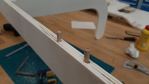
I start a process of sanding, glueing fixturing and even adding a bit of extra support of wood with wood dowels to support the floating peace of the table top. My College Herman helps me with glueing a peace of thin wood inside the crack the dowels and we use some more sawdust and glue. Now it’s drying lets hope it will hold-up tomorrow.
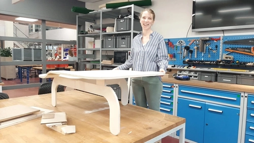
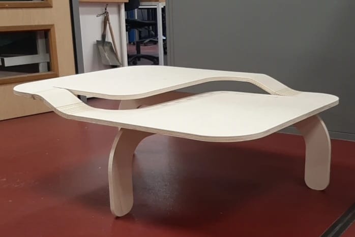
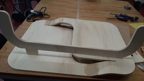
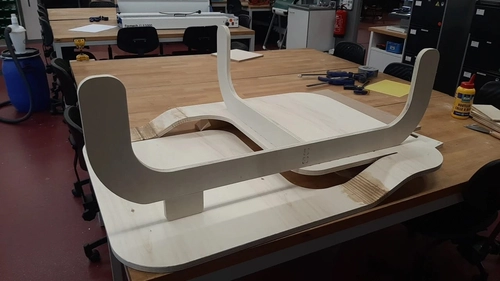 Everything took me more time then anticipated. But I do still really like the floating look of the table with the legs and the next morning the glue hold the peace! Happy me!
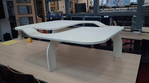 I will not finish the upper side with some more glue and sawdust mixture and after this has dried sand everything.
Group assignment
Working with the Shop bot at Waag with Vcarve
Safety
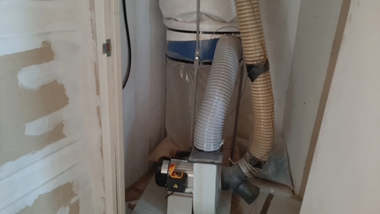
Don’t hit the screws with the milling bit. If you do hire hazard is a real problem. If it goes wrong remove the bag from the extractor as fast as possible and check if the woodchips are not catching fire. If it’s a big fire in Waag close the doors behind you.
In your CAD design you can make drill holes for the screws so you know where the screws are when you mill the design later. Specially helpful when working on big plates that need screws in the middle. Depending on the size of your project and your settings you need a certain amount of screws. Average would be every half meter you need a screw.
Most important try to member the movements of the machine. No tools or stuff on the machine or next to the machine
Watch out for you end stops in all direction, the stepper motors wont know their origin when you moved passed the end stop. Make sure you do the homing very well.
Wear earplugs and safety glasses
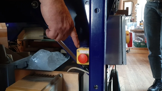
Emergency button. Note, if you press it the spindle will keep turning so stop the spindle with the key, it’s not connected to the on of button. But you can also pause the machine with space in the software and lift the spindle using the z heigh
Machine
Shop bot: X long axes Y small axes
For the extractor put it on separately. The tools for the spindle are together with the key for the machine on the same cord. Spindle
Check if the spindle turns: put the key in and turn for the spindle.
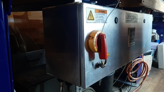 Put the machine on and then the software so it can communicate
At the back there is a wing nut
Nut with the collet (imperial american) replaced for metric sizes collets
Put the machine on and then the software so it can communicate
At the back there is a wing nut
Nut with the collet (imperial american) replaced for metric sizes collets
 Two flute end mill 5 mm
First put the collet in the nut until it clicks. After that push the bit in from below put it up high enough!
Carbite steel coating need to clamp it of the soft material
Fasten the bit again with the two tools
Two flute end mill 5 mm
First put the collet in the nut until it clicks. After that push the bit in from below put it up high enough!
Carbite steel coating need to clamp it of the soft material
Fasten the bit again with the two tools
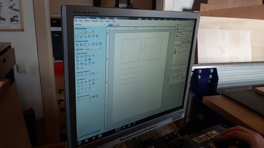
CAM Vcarve8.0
- Start with creating a new file
- In the Job setup - put in the numbers of your plate material in mm X and Y. And measure the thickness.
- Press OK to set the stock
- Import a file type DXF or SVG, you can also create some simple vector lines inside this program.
- Make sure your lines are closed go to edit -> select all open vectors * and go to edith objects -> join open vectors.
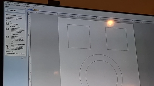
- Create fillet (use same size as millingbit). Set the tool diameter and select the corners. The side where you click the gone will come.
- Draw circles for screwing the sacrificial layer using the draw circle tool, diameter of the milling bit.
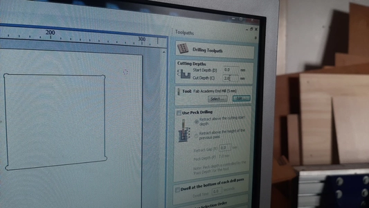
Toolpaths
- On the right side of the screen go to toolpath
- start with selecting the right tool size and type of mill
- select drill toolpath feeds and speeds and plunge rate are setup for you, don’t alter in this menu. First select and than go to edit here you can change the settings. Pass depth (for traveling)
- select al the holes for the screws and generate the toolpath
- In preview mode look at the toolpath
- Toolpath list now has one toolpath for drilling the holes
- Select profile toolpath inside select climb select machine vectors: Inside show advanced toolpath options for the toolpath offset this depends on the climb: minus allowance / tolerance or conventional plus allowance / tolerance inner cuts or other cuts don’t matter
- Add tabs 5 mm length 3 mm thickness length thickness You can generate them or select them where you want them
- For wood we use 12000 f.p.m. and speedrate 50 mm/sec plunge rate 20 mm/sec
- Profile toolpath outside select climb
order for the shapes first inner shapes - pocket toolpath set Stepover spindle speed 12000, 60 percent so your not traveling over it’s line. You can choose between offset and raster Pocket allowance offset in 0.2 mm for example so everything fits
offset allowance
- save toolpath make sure you save two files. One for the screws and the other one without the screw holes!! Never select the output direct to machine button
- fill name use a good name (use your name)
Shopbot software
Press K and then arrows left right
Page up page down for the z
 Press button Home machine x and y
 Press zero Z to level the z with the metal plate below the bit.
Put away the metal leveling plate back in the slot.
Vacuum the bed so it’s clean. Sacrificial layer must be flat. Sand away bits that aren’t flat anymore because of screws
Put in the material level it
X Y move to corner with Zero 2 XY of material and set to 0
Press zero Z to level the z with the metal plate below the bit.
Put away the metal leveling plate back in the slot.
Vacuum the bed so it’s clean. Sacrificial layer must be flat. Sand away bits that aren’t flat anymore because of screws
Put in the material level it
X Y move to corner with Zero 2 XY of material and set to 0
Forgot to save the XY before setting a new 0
Put files on desktop
Put on the dust extractor
Put on the spindle speed manual
File partfile - drill start file
Put off spindle -
Press on the plate to make sure it won’t lift
 Woody screws you can reuse
Don’t home and make sure to put spindle on again
Second pass rename the file nu capitals and open it
Press the Green start button
Sound is bad so we put it to feed rate 18000 the sound is a bit better but still not great
Woody screws you can reuse
Don’t home and make sure to put spindle on again
Second pass rename the file nu capitals and open it
Press the Green start button
Sound is bad so we put it to feed rate 18000 the sound is a bit better but still not great
First try:
Bit diameter 5
The result shows a lot of burrs
Cut depth might be too steep; we chose 4,5
Possible blunt milling bit, checking it with the loop
Spindle speed (feed rate) to slow (12.000) 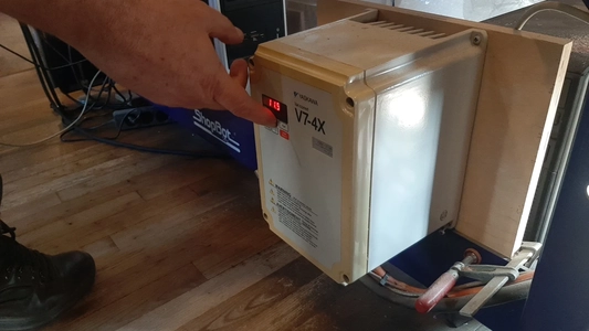
Second test: We change the milling bit We change the spindle speed to 18.000rpm
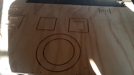
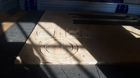
Test runs Waag Shopbot
Leo and I continue to work on the test runs for testing: runout, alignment, fixturing, speed, feeds,(bit slower bit faster) materials.
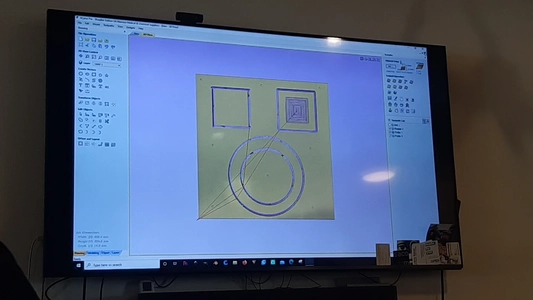
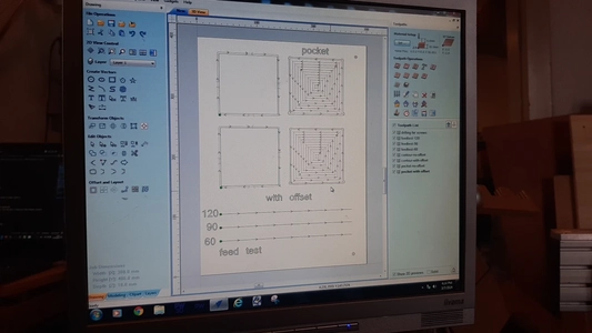
Leo documented the results of the test runs and I the setup of the design. We draw four squares and three lines to test the following things:
- Cutting pass depth 3 mm We try again using 2,5 cut depth RPM : feedrate depends on the numbre of flutes and thickness of the material. 20 till 120 mm/s 6 mm end mill RPM
1 ~ 5 mm wide Testing feeds
We make 3 lines and we keep the the speed the same 18.000 RMP The cut depth we set to 9 mm for the pockets? We use the Climb direction
For our test we use 3 different feed rates:
- 120
- 90
- 60
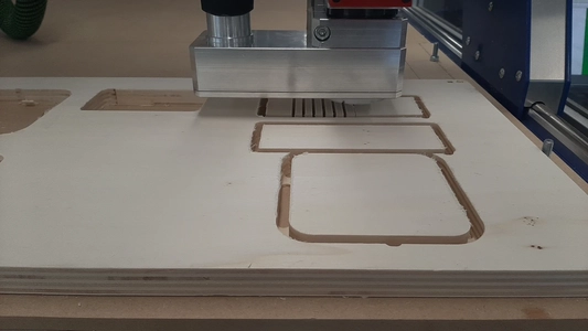
Testing the alignment We will mill out one square to test is it’s actually square using a 90 degrees corner measuring tool called blokhaak in Dutch. To mill out the shape we use 4 tabs We use tabs of the size: 8 mm x 3 mm and use 4 of them in total on each side 1.
Testing the runout
We will mill 4 squares
The left ones we will use an outermill line and go through the material
The right ones we will mill an inner line and use bog bones on the top and t bones on the bottom corners. to see if it’s having an offset.
The upper two squares have no offset
The bellow to squares have an offset of -0.2 mm
We create different toolpaths for all the elements on our sample.
Here is the design file
 I have to catch the train now, you can see the results in Leo’s documentation.
Reflection
This was a hectic week for me I kept thinking things will go faster then it did. During the whole week actually, the design process the CAD drawing the CNC milling and especially the work after milling. I’m glad I had help from people this week and also I learned tons. I feel really confident to mill something in 2D on the machine at our University now and I didn’t at all before this whole process of making this table. I wished I had more time to do a second version since I still really like my design put technically I wished I made it a big less fault sensitive for myself looking back to it. Thing I would have changed:
- I would create a table leg that would support the floating table top maybe even to use as a guide for the bending
- I would also change my origin from the stock point to a dogbone in the design so I can fixture the woodenplate in the exact same spot when I flip the table top to mill the back
- I would check my wood if it’s perperdicular
- I would do test runs for EVERYTHING so also the drilling..
- I would make the table less wide and I would make the bending length wider to have a bigger glue surface.
- I would use more screws to prevent the plate from bending
- I would use tabs in the middle slot to prevent the plate from bending
What I did really good this week was my preparation. I allready made the sacrificail layer the week before as well as ordering the right mills, booked the machine and fixed and saw the wood. I highly recomend this since you need all your time this week for the actual making.
What’s left to do it give it a good sanding and put in in lacquer and take it home!
The documenting was pilling up and also wasn’t able to work on the final project this week. Hope next week will be better in terms of time management.
Design file
- here you can download the Fusion360 design file as a STEP file format.