pico music
intro
Furby sounds from a XIAO RP2040
The goal of this week is to dive into programming of embedded microcontrollers. As group assignment:
- Browse through the datasheet for your microcontroller
- Compare the performance and development workflows for other architectures
- Document your work to the group work page and reflect on your individual page what you learned
and as individual assignment:
- Write a program for a microcontroller development board to interact (with local input &/or output devices) and communicate (with remote wired or wireless devices)
For my individual assignment I will look into the RP2040. The whole python / micropython / raspberry thing has been only margiannly touch my practice (I have used Pi’s for powering printers, media servers, escaperoom puzzles and video loopers but I tend to stay away from them since they are still computers with an OS on an easily corruptable tiny SD card)
For my final project a logical choice would be a Teensy, since they come equipped with many libraries and tools to do audio. However, I am interested to learn whether an RP2040 in c or python can achieve what I want (realtime control of seemless looping at variable playback rate)
Recitation in the lab
During Erwin’s short crash-course into embedded programming a number of basic (and more advanced) topics are discussed such as sense think act - (input - process - output) and some quick advice how to work on your project, translate ab idea to functions, functions to language, language to code. Here follow some of the notes I took:
-
check: ansi-C code for arduino and compare with
-
tinyGo: mix between python and go (google)
-
Rust: (mozilla) force you to write secure code.
-
MicroPython: / CircuitPython = micropython + more
-
RTOS -> task scheduling
-
ESP32 dual core -> core0 runs FreeRTOS for WIFI and Bluetooth
-
new FreeRTOS -> new standard is Zephyr (scalable, optimized, secure, uses a Hardware Abstraction Layer)
-
compiler:
avr-gcc -mmcu=atmega328p -02 -g -o code.hex code.c -
programmer:
avrdude -c avrispmkii -p m2560 -P usb -U flash:w:firmware.hex
(oh, wait, I didn’t set the fuse bits on the Arduino Mega for my 3D printer last week. THat might be the reason that the bootloader does not work? - hmm. perhaps not, Arduino will set fuse bits when flashing a bootloader, so it is still probably the CH340 serial to USB thing)
-
microcontroller architecture - see AVR RISC
-
selection criteria:
- IO ports
- Other periferals: ADC, DAC, SPI, I2C, UART, USART, Timers, Sleep states
- power consuption/speed
- programming environment
- cost
-
Memory things:
- fuse bits (clock prescale, bootloader section, etc)
- registers (processor maniupulation, Timers and Uart etc)
- SRAM
- DRAM
- Flash (program storage)
- EEPROM (nonvolatile memory for settings)
-
Troubleshooting:
- serial print(ln) instructions
- blink LEDs
- logic analyser on pins
- oscilloscope (analog signals)
-
Arduino environment / library uses resources: RAM (bit for bootloader), Timer (allocate 0 already), UART, ADC. Basic functions are pinMode, digital/analogWrite, read, serial printing etc.
- 8 bit: char or uint_8t
- 32 bit int uint_32t
-
use PROGMEM wisely. Keep interrupts small. Don’t use global variables
-
debounce a button: not with interrupt or timer but rc filter of 20k-50k (internal pull-up) 10n-100n
-
bitwise operators :) &, | -> |= and &= for bit masking.. (1«6) shift left, shift right, ~ invert,
Demo of bare bones cpu: it is just flippin’ bits! Also the evil mad scientis digi-comp II digi-compII.com -> fun stuff! The following video shows computing in education.. brilliant!
Evil Mad Scientist's DigiComp in action
Subsequently Henk briefly showed how to set up Go, compile a short hello world and make it run on the XIAO RP2040.
mkdir test
cd test
go mod init blinky
make file blink.go:
The sources were obtained from tinygo.org. (the response to Henk’s enthusiast demo of doing a bare-bones tiny-go install, memory device mounting in Linux and making an LED blink was rather low, but this might have had something to do with approaching lunch time). As a final remark came that Go has not much library support (yet), so it is not recommended for a final project
group assignment
Deep dive into a microcontroller datasheets such as the ATmega328P sheet and RP2040 datasheet (which we did on screen) and do blinkies. After group-wise browsing the sheets on screen, we divide the work. Joe starts work on the standard Arduino environment, Leo will try go - Vera and Joany will try to get microPython to work with VScode - I will try microPython using Thonny (and later c / arduino framework using VScode as well)
Atmel's ATmega328 inner workings from the data sheet
Now the Atmel documentation is very technical. The XIAO documentation is mostly practical. The RP2040 datasheet however is written very well (human readable).
The RP2040 overview is a bit different, but similar internal system components can be recognised:
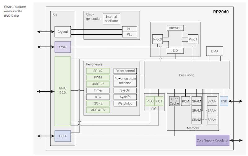
system overview of RP2040
Now this RP2040 controller can be housed on any board. The PICO board populates most of the RP2040 pins outwards. The XIAO form factor seriously limits the amount of available pins:
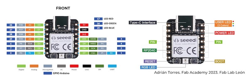
Pinout of the XIAO RP2040
The RP2040 on the PICO has many more pins, which also means that unclearities can form when having to remap libraries and sources written for the Pico to the XIAO and vise-versa
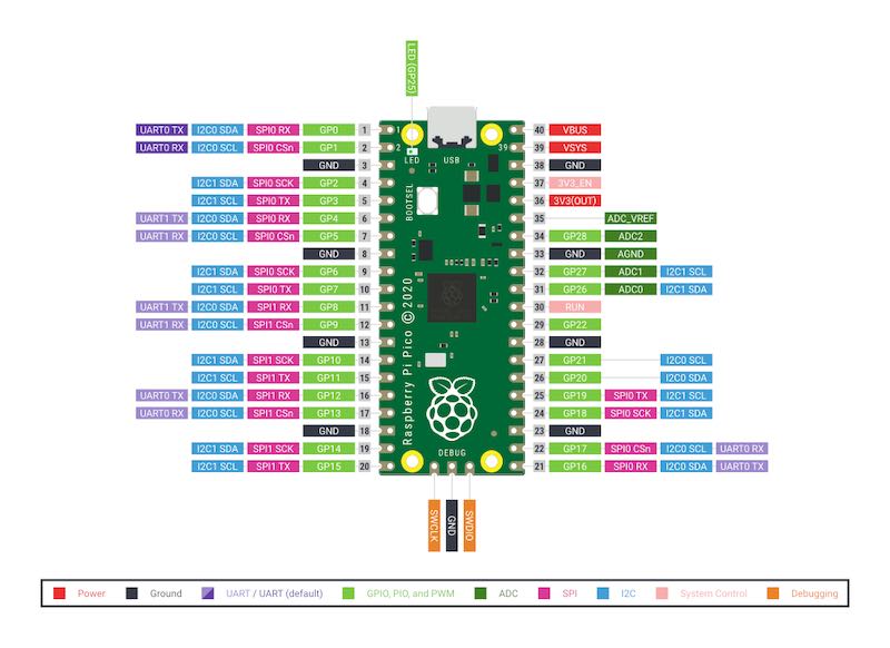
Pinout of the RP2040 on the Pico
Blinky in micropython with thonny:
Following this tutorial I take the following steps:
- install thonny from the following website https://www.thonny.org. (I already had it installed on my system for a previous attempt with a Raspberry Pi Pico so it needed to be updated)
- hit reset and boot (so, reset, boot, hold, release)
- the controlloer will show up as external drive
- on this drive there is an index.htm page you can visit with your browser
- go to micropython website
- download *.UF2 file (Raspberry Pi Pico, not the ‘W’)
- drag and drop file to the drive. Drive will eject (on macos) automatically
- go back to thonny
- go to tools -> options -> interpreter -> Port: select the correct serial port.
- terminal should connect :) - this is called ‘REPL’, the -interactive- python prompt.

selecting the port in Thonny
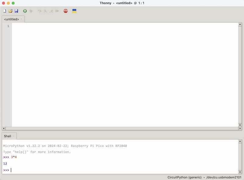
the interactive communication prompt
type code:
from machine import Pin
from time import sleep
ledBlue = Pin(25, Pin.OUT)
ledRed = Pin(16, Pin.OUT)
ledGreen = Pin(17, Pin.OUT)
while True:
   ledBlue.value(0)
   sleep(0.3)
   ledBlue.value(1)
   sleep(0.3)
   ledRed.value(0)
   sleep(0.3)
   ledRed.value(1)
   sleep(0.3)
   ledGreen.value(0)
   sleep(0.3)
   ledGreen.value(1)
   sleep(0.3)
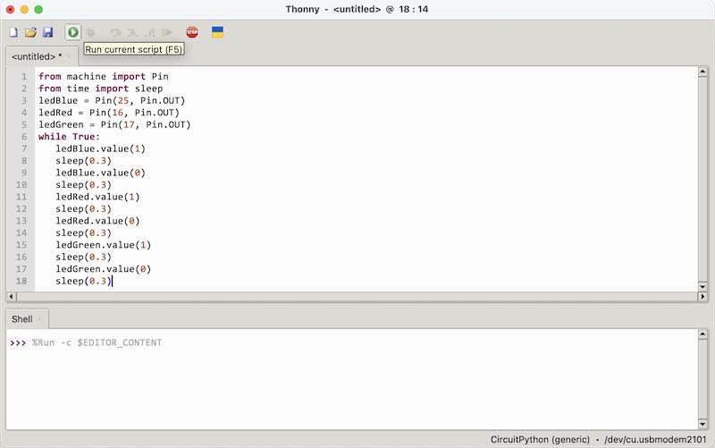
blinky program running from the REPL terminal
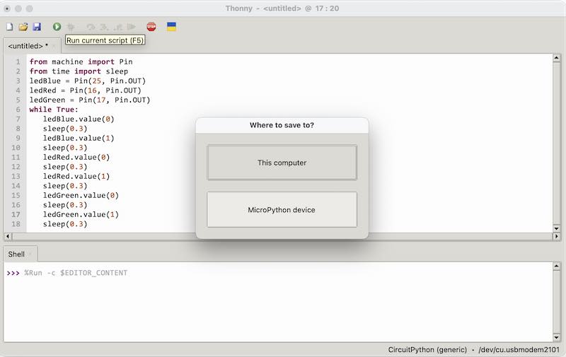
saving, either locally or as embedded program
- now with buttons ‘run’ and ‘stop’ the program can be run through REPL.
- save: option to PC or to device
- save to PC: need to use REPL again next time to load and start the program
- save to device (only after you stop the REPL session): main.py is the name of a program to run on startup
- reset: the main.py program is started…
- you can restart the connection by going to tools -> options -> interpreter -> Port. The running code stops and REPL prompt is there again.
blinky with Arduino core in VScode
Now, since most of the documenting and editing takes place in vscode, it makes sense to try a different workflow and use vscode to support the development of embedded software. Again, we are working with the RP2040 on XIAO
- install platformio through the extensions manager
- start up a new project in the platformio main panel for RP2040 PICO (Rasberry Pi Pico)
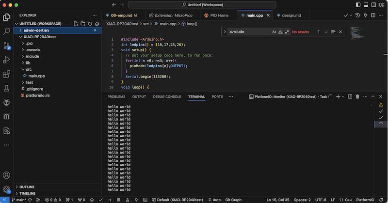
- go to the ‘src’ directory and edit the main.cpp file, see the file used below
- bottombar: compile (V) and program (->)
- bottombar: the small ‘plug’ icon is for the serial terminal
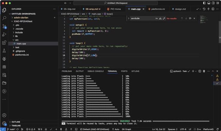
Setting up a blinky using platformio
With the program a very simple blink on pin 17 was executed (one of the 3 on-board LEDs on XIAO RP2040). Next up I tried printing from the serial port to the serial terminal:
Caption for Image
blinky with Arduino IDE
Also to make sure everything is still working in the Arduino IDE I tried a similar blinky, now also using the NeoPixel style RGB-LED, in the Arduino IDE. I used the 1.8.9 version since (on macos at least) the 2.x.x version still gives trouble with other controllers than ‘simple’ Arduino Uno or Mega boards.
- library manager: RP2040 XIAO from the
https://github.com/earlephilhower/arduino-pico/releases/download/global/package_rp2040_index.jsonarchive (which has to be added to Arduino -> preferences -> Aditional Board Manager url’s before it can be installed). The amount of examples is great!. Also the support from Seeed is elaborate.
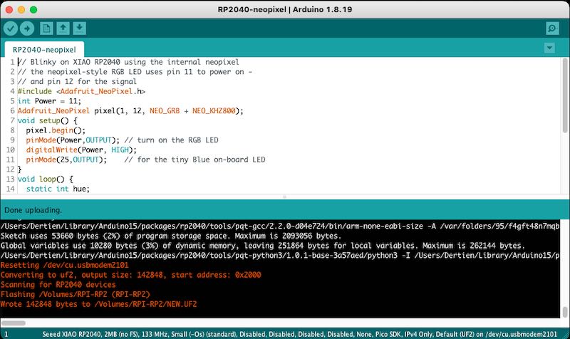
Blinky program in the arduino IDE
// Blinky on XIAO RP2040 using the internal neopixel
// the neopixel-style RGB LED uses pin 11 to power on -
// and pin 12 for the signal
#include <Adafruit_NeoPixel.h>
int Power = 11;
Adafruit_NeoPixel pixel(1, 12, NEO_GRB + NEO_KHZ800);
void setup() {
  pixel.begin();
  pinMode(Power,OUTPUT); // turn on the RGB LED
  digitalWrite(Power, HIGH);
  pinMode(25,OUTPUT);    // for the tiny Blue on-board LED
}
void loop() {
  static int hue;
  static unsigned long looptime;
  if(millis()>looptime+99){
    looptime = millis();
    hue+=10; // big steps
    if(hue>255) hue = 0;
    if(digitalRead(25)) digitalWrite(25,LOW);
    else digitalWrite(25,HIGH);
        pixel.setPixelColor(0, pixel.Color(hue,255-hue,0)); // Set pixel 0 to value 'Color'
        pixel.show();
  }
}
Note that in this blinky example I already used the Neopixel library by Adafruit which was already present on my system.
individual work
VScode
Next up was the need to add libraries to VScode, to make it possible to control different hardware with the XIAO RP2040. In the platformIO board manager there is not a direct support for XIAO, but the standard Raspberry Pi Pico, using the same RP2040 controller, is well supported. In order to get started with the libraries I took the following steps:
- platformIO (already installed)
- select RPI PICO (for RP2040)
- switch between tabs in VScode using ctrl-tab
- install libraries in the folder ’lib’
- better: install libraries through Platformio’s library manager.
the blinky source for XIAO
The easy blink example was working right out of the box, blinking three small LED’s on the XIAO.
#include <Arduino.h>    // arduino framework in PlatformIO
// simple blinky on three LEDs on board of a XIAO RP2040
// also printing "hello world" to the terminal
int ledpins[] = {16,17,25};
void setup() {
  for(int n =0; n<3; n++){
    pinMode(ledpins[n],OUTPUT);
  }
  Serial.begin(115200);
}
void loop() {
  static unsigned long looptime;
  static int n;
  if(millis()>looptime+199){
    looptime = millis();
    Serial.println("hello world");
    for(int i = 0; i<3; i++){
      if(n==i) digitalWrite(ledpins[i],HIGH);
      else digitalWrite(ledpins[i],LOW);
    }
    n++;
    if(n>2) n = 0;
  }
}
components and libraries
For my final project I would like to use the RP2040, either as Raspberry Pi Pico or as XIAO RP2040 form factor - I think the XIAO will be sufficient regarding the number of available pins. I need to add the following hardware:
- OLED display
- input knobs (potentiometer / encoder). I think 3 potentiometers (A cursor, B cursor, modulation) and an encoder (file selector)
- control inputs
- servo outputs
- audio out
Seeed has produced a very nice expansion board which I already had for a different project. This board has an on-board buzzer, button, OLED display, Realtimeclock, SD card slot and 4 Grove sockets (4-wire connection with power, gnd and two signals: analog, digital, Rx/Tx or I2C). Most of the examples on the seeed wiki are however shown for the SAMD XIAO.
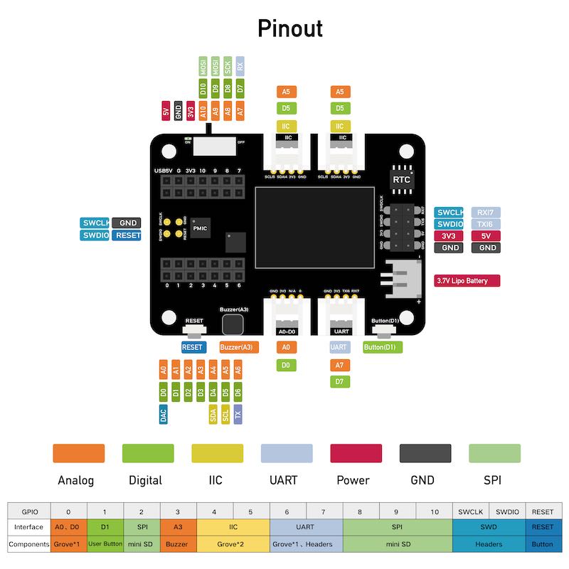
Expansion board for XIAO boards
Especially when a number of items use I2C (servo controller, display, encoder) then it is feasible to use a XIAO. On board of the XIAO there are three small LEDs (pin 25, 16, 17) and an RGB neopixel LED (power pin on pin 11, signal pin on pin 12). The setup with Arduino (and Arduino’s library manager) works. When I try to make things work in VScode I hit a snag. The Leds, RGB leds and standard serial port are working, but other periferals (OLED, audio, external serial port, SD card) are not. So there is a difference between the libraries, pin mapping and perhaps even the PIO programming between the platformio toolchain and the arduino toolchain. Below the result of a deep-dive in this rabbit hole with eventually a simple (out of the box) solution.
A nice source to get working with pico and platformIO is this one. The problem with using I2C / Wire.h.. has been reported on by seeed users and also regarding the use of the SSd1306 display whereas Seeed reports it to be working at least with SAMD.
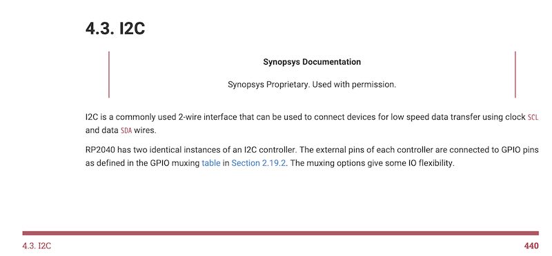
2 physical I2C units present (from the RP2040 datasheet)
One of the main sources of issues might be that the RP2040 has two hardware I2C uarts which can be wired internally to almost any set of pins which you can do in software, but some libraries choose to do for you under water - explained well in this tutorial In the Arduino IDE (1.8.9) everything I2C DOES work, however the used pin numbers (0,1) for SDA and SCL are not always in sync with the description.
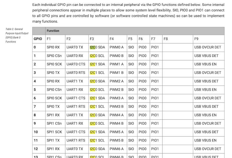
Many pins can have many functions on the RP2040 (from the RP2040 datasheet)
Now, instead of having platformIO use its (separate) libraries, it would be an option to use existint libraries in place. However, this also poses many conflicts between the arduino core and used library set - in either toolchain install (VScode or Arduino) they come as combined package. Finally it can also have to do something with how the PIO is programmed (at the moment I don’t know if the arduino toolchain comes with a flexible, build in or - none- programming of the pio)… (it also doesn’t help that PlatformIO is abbreviated as pio too). see also this
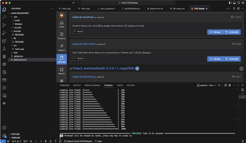
installing libraries through platformio. Not working at this point
Another test is then to use platformio’s library manager instead of copying arduino libraries into the lib folder. The intended libraries for controlling the display (Ug8lib.h) are sadly not available
to install libraries: CLI advice : platformio lib search "header:U8x8lib.h"
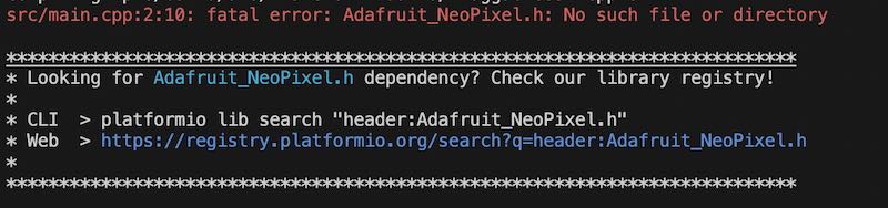
using CLI to install libraries
On suggestion of Henk I checked whether platformIO has been installed correctly (so first brew install platformio) (takes another 6 GB!). (Now I might have two complete toolchains).
So, conflicting library problem. Arduino uses RP2040 HW set of libraries. Setting them in platformio.ini does not work (yet). adding libraries one by one compiles, but the wrong Wire.h will be included. I compared both libraries (Arduino toolchain’s working I2C lib and VScode NOT working RP2040 Pico lib for XIAO). Indeed, different pin mappings are used:
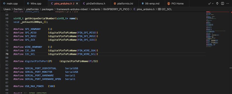
Pin definitions used in VScode. Only one I2C unit available
A different other option would have been to use Arduino CLI and stop with PlatformIO altogether. The best overall solution would still be real XIAO XP2040 support for PlatformIO, but this is still an outstanding pull request. Max Gerhardt however did the work on a version that understands the pin-mapping differences of XIAO RP2040 and Pico. Now we’re cooking! More on editing the platformio.ini file can be found here and here
For the Seeed expansion board there is this collection. However, after installing the following hardware definitions and environment settings in platformio.ini the regular library download / support seems to be working and I can start writing programs as initial sketches for my final project…
[env]
platform = https://github.com/maxgerhardt/platform-raspberrypi.git
framework = arduino
board_build.core = earlephilhower
board_build.filesystem_size = 0.5m
lib_deps =
	adafruit/Adafruit NeoPixel
	adafruit/Adafruit SSD1306 ; needed previously to comment out the pgmspace.h

[env:seeed_xiao_rp2040]
board = seeed_xiao_rp2040
I quickly tried to run some example code for the display using I2C in VScode and it worked..:
testing the XIAO RP2040 on the seeed expansion board
Furby sampler demo
Using the Seeed XIAO expansion board (there is a policy against breadboard. OK. I don’t agree but can live with that. Anyway, I strongly believe in modularity and reusability of components, so I rather first experiment a bit with a series of GROVE modules before I go and design/mill my final board). Did I mention I -LOVE- grove? - I would like to develop the first sketches to check sound playback, memory, use of screen etc.
A good overview and explanation of available libraries and functions for RP2040 in the Arduino Framework (targetinng Raspberry Pi Pico) is this pages
In the code I combine two examples. First one is the Adafruit SSD1306 OLED display libraries - which already offers basic functionality for drawing lines etc. Next up is the <pwmaudio> library which allows to play back wav data on a PWM pin as separate (cp) process. (need to look better in to that)
In the code I load a furby sound sample from archive.org into flash (and RAM) memory as header file. Better would be to use PROGMEM so the file is left as datablock in flash rather than copied from flash to RAM. I use an application called wav2c to turn a 16bit 44100khz mono WAV file into a headerless wav as data block in a header file furby.h. The conversion (re-sampling) of the Furby file is done using audacity
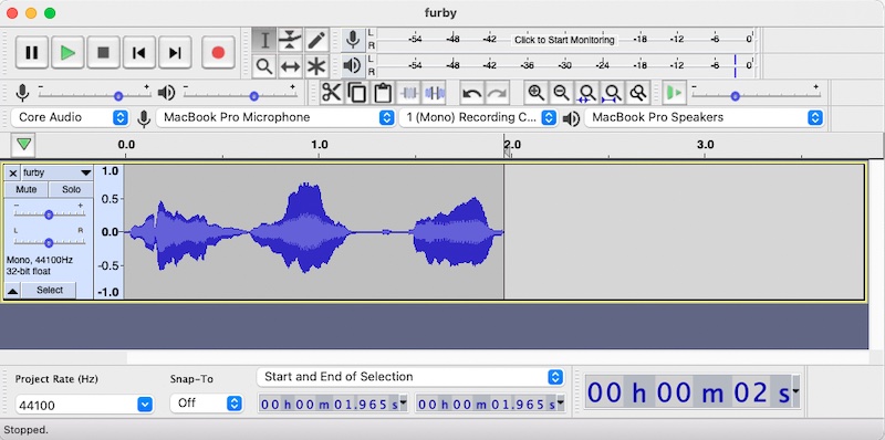
using audacity to re-sample the furby sound
Next, I used wav2c to convert the audio file to a ‘headerless’ array of wav data:
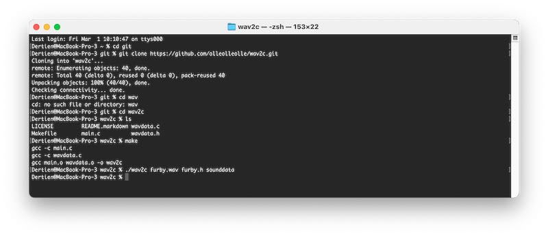
pulling, compiling and using wav2c in one go :)
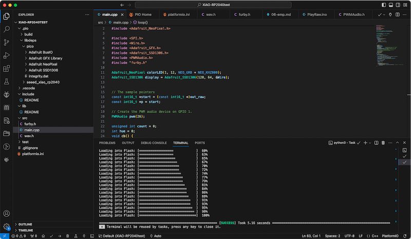
It is very nice that even in the data pattern (array of values in furby.h) you can recognise the audio data very well, especially when scrolling:
Audio shown in code .. you recognise a wave
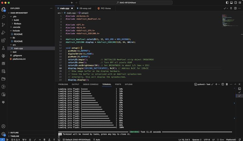
Leading to the following code example:
// furby sound sampler audio test with OLED display
// playing a sample from memory.
#include <Arduino.h>            // arduino core / framework
#include <Adafruit_NeoPixel.h>  // library for the neopixel LED
#include <SPI.h>                // not used but necessary for other displays in the SSD1306 lib
#include <Wire.h>               // the I2C communication lib for the display
#include <Adafruit_GFX.h>       // graphics, drawing functions (sprites, lines)
#include <Adafruit_SSD1306.h>   // display driver
#include <PWMAudio.h>           // cp process to play audio on PWM pin
#include "furby.h"              // converted furby sample data (using Wav2c)
// initialise limor's stuff
Adafruit_NeoPixel colorLED(1, 12, NEO_GRB + NEO_KHZ800);
Adafruit_SSD1306 display = Adafruit_SSD1306(128, 64, &Wire);
// The sample pointers
const int16_t *start = (const int16_t *)out_raw;
const int16_t *p = start;  // the real sample value pointer
// Create the PWM audio device on pin A3 (internal buzzer on Expansion board)
PWMAudio pwm(A3);
unsigned int count = 0; // check where in the sample you are, human readable
volatile int hue = 0;   // to cycle through LED colours (and misused as frequency setting)
void cb() {             // thread process to do audio update regularly
  while (pwm.availableForWrite()) {
    pwm.write(*p++);
    count += 2; // was 2
    if (count >= sizeof(out_raw)) {
      count = 0;
      p = start;
      pwm.setFrequency(22050+hue*120);
    }
  }
}
// now for the code
void setup() {
  pinMode(11,OUTPUT);         // power pin for Neopixel LED on XIAO
  digitalWrite(11,HIGH);      // turn on the Neopixel power
  pinMode(25,OUTPUT);         // blue LED on XIAO
  colorLED.begin();           // INITIALIZE NeoPixel strip object (REQUIRED)
  colorLED.show();            // Turn OFF all pixels ASAP
  colorLED.setBrightness(50); // Set BRIGHTNESS to about 1/5 (max = 255)
  display.begin(SSD1306_SWITCHCAPVCC, 0x3C); // Address 0x3C for 128x32
  display.clearDisplay();     // start the screen
  pwm.onTransmit(cb);         // start the audio playback
  pwm.begin(22050);           // set the playback frequency
}
void loop() {
  display.clearDisplay();
  for(int i=0;i<display.width();i++){   // this is for building up a sound wave picture
    int p = sounddata_length/display.width(); // scale the data to the full screen width
    display.drawLine(i,display.height()/2+out_raw[i*p]/4, i,display.height()/2-out_raw[i*p]/4, SSD1306_WHITE);
  }
  int cursor = display.width()*count/sounddata_length;
    display.drawLine(cursor,0, cursor,display.height(), SSD1306_WHITE);
    display.display(); // Update screen with each newly-drawn line

  static unsigned long looptime;
  if(millis()>looptime+99){ // run this code at 10Hz
    looptime = millis();
    hue+=10;                // cycle hue value for RGB LED
    if(hue>255) hue = 0;
    if(digitalRead(25)) digitalWrite(25,LOW); // blink the LED, 5Hz
    else digitalWrite(25,HIGH);
    colorLED.setPixelColor(0, colorLED.Color(hue,255-hue,0)); // Set pixel 0 to a color between red and green
    colorLED.show();
  }
}
One of the interesting powers of C (for this project) is that with pointer p in void cb() you have direct control over which bit of memory is being played back, allowing for rapid switching and looping. When changing this, for example by skipping two bytes it easily picks up another block of memory to play. In my case (quite surprising) it ended up playing fragments of a previously loaded wav audio file. Indeed, one of the security risks that other languages (go, rust) probably avoid.
furby sampler code in VScode
Drive space usage
After installing platformio AND arduino toolchains for the RP2040 (and others) drive space is reduced by 10’s of gigabytes. Since I would like to keep my entire -everything- below 1TB, some checks on where the ‘bloathing’ comes in might be useful. A quick fix is clearing out arduino’s staging folder in which packages and versions of libraries and toolchains are stored. In my case good for 4.5GB of disk space. The Arduino sketchbook folder (in which also libraries and board descriptions are placed) amounts to -just- 1 GB.
Also the platformio packages (~/.platformio/packages) directory is occupying a whopping 8.5 GB. Not sure what to remove there, might need to check out first whether the build-in library manager for platformio helps.
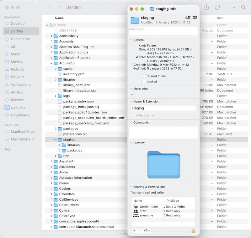
the arduino staging folder
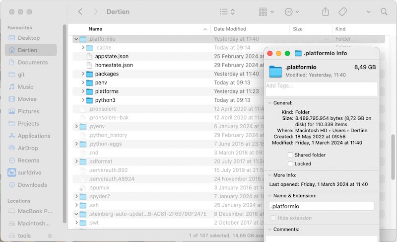
platformio is Huge!
learning outcomes
Implement programming protocols. I used a number of tools and managed (eventually, yay) to get all libraries for XIAO working in VScode (even though I already had everything working in Arduino. Never step back :)
evaluation checklist
The task list for this first week (for personal reference)
- Linked to the group assignment page
- Programmed your board to interact and communicate
- Described the programming process(es) you used
- Included your source code
- Included ‘hero shot(s)’
lessons learned, tips and tricks
(or, the most insightful mistakes I made)
- It is always the case that you spend 6 hours trying to find the source of a problem (in my case I2C definitions an dpin mappings) and right when you are at the root of the problem you find somebody else’s working solution….
- pin mapping between libraries, platforms, datasheets and toolchains is never straightforward. apparently
left for todo
- For installing Arduino support for SAMD
- try micropython with vscode and give python another shot?
- use breakpoint debuggin from the Arduino terminal using one of the new jtag / openocd like programmers
- pio programming, [check out this tutorial](https://www.digikey.nl/en/maker/projects/raspberry-pi-pico-and-rp2040-cc-part-3-how-to-use-pio/123ff7700bc547c79a504858c1bd8110) and use leo’s work as stepping stone :) and perhaps this link too
- the second serial port (HWserial) does not seem to be working (or, it interferes with audio playback. Needs separate testing)
- this nice blog post explains how to do the same thing (pwm audio playback) in MicroPython
- use the two cores in a dedicated manner, so audio playback is done on one, and user interfacing is done on the other (!)
reflection
I have been working with microcontrollers for quite some time now. My first robots were programmed with an Acorn BBC computer, and after briefly dabbling with 80C32 and attemting to build my own eprom programmer, I fortunately stumbled upon the AT90S1200. A flash programmable microcontroller with 32 registers, no RAM which you could program in Assembly. My first -working- embedded control project was a MIDI keyboard powered by this controller. Later I went on to put atmel controllers in almost all projects I worked on. For larger robots and bigger machines I usually stuffed in More Controllers and made them communicate or network. Arduino certainly eased the way (or wormed itself in like a cuckoo). I used to work with Atmel Studio (later with GNU GCC support) or ImageCraft’s (paid) C-compiler. For educational purposes I designed our own version of the MIT 6811 Handyboard using ATmega8535 (and later ATmega32 in the Arduino environment)
So. Most of my projects are still 8 bit, and for some reason the need for more processing power, memory and connectivity has never been an issue. So it is nice to take on a project (already this week) that my small 8-bit friends would have seriousl trouble with, but the cheap, sleek and small RP2040 can take on easily: playing audio with real-time modification, while at the same time putting everything on a detailed display. The future is going to be bright :)
copyrights and references
- I used images from the raspberry pi website and from the XIAO website for easy referencing.