Week 6
Embedded Programming
Organizing
checklist
| group assignments | — |
|---|---|
| Browse through the datasheet for your microcontroller | |
| Compare the performance and development workflows for other architectures | |
| Document your work to the group work page and reflect on your individual page what you learned |
| individual assignments | — |
|---|---|
| Write a program for a micro-controller development board to interact (with local input &/or output devices) | |
| communicate (with remote wired or wireless devices) |
I made the starter kit examples of arduino with the arduino uno to have a bit of an understanding about coding and using different input and outputs to prepare myself fot the Fabacademy in December. Before this I used the arduino IDE and library before to move a servomotor and do some blinking LED and that’s my experience with this subject so lot’s to learn this week!
| Personal assignments | — |
|---|---|
| — | discover functions |
| — | read about the microcontrollers and choose a chip for final project |
| — | Find compatible libraries |
| — | preparations for making something big week (wood and milling bits) |
The basics
Since I’m very new to this whole world of micro controllers I will start by trying to explain what I learned this week in my own words. Starting with some basic terms. Getting my notes sorted and understandable was hard for my I ended up watching the recitation twice as well as Neils lecture.
| term | meaning |
|---|---|
| Hertz | Cycles per seconds, 1 Hertz is one round per second. In the world of computers we usually use MHz or GHz. One megahertz is 10^6 hertz. Use this to calculate the speed pins can communicate with a processors core. Programming language and architecture influence this speed comparisons benchmark page witch measures the time to output input speed ratings for many different processors we using |
| Word size | how much information a processor can operate at the same time. simple processors 8 bits, complexer ones 32 bits, my computer 64 bits. |
| Registers | (bite) each bit in the bite is a setting, you can read this in the datasheet |
| Micro controller | chip with lots of interfaces to talk to the outside world |
| Compiler | A Microcontroller can’t understand the language yet. We need an compiler to translate the human readable code to machine readable code (binary) compiler does this |
| Programmer | We need a programmer (board with microcontroller) to put a program in another micro controller that for example doesn’t have a USB programming function |
| Bootloader | 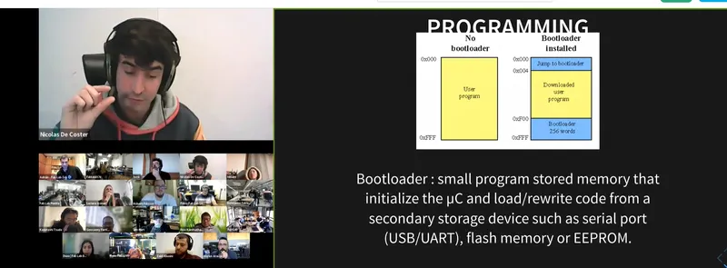 small bit of code (program) that you put on your chip to store a new program through your chip. It takes a bit of the memory of the chip. You can overwrite it small bit of code (program) that you put on your chip to store a new program through your chip. It takes a bit of the memory of the chip. You can overwrite it |
| Micro processor | your computer, it can multiply, add stuff super fast |
| Peripherals | how the processor talked to the world around it. For example hardware device to make the computer do what you want it to do |
| CPU | central processing unit hardware in a device to read and perform the code |
| Peripherals | meaning |
|---|---|
| ports | send data out on pins and get data in. |
| GPIO | general input output ports |
| A/D | takes analog voltage and turns it in digital data. |
| Comparator | compares two voltages. |
| D/A digital to analog | takes digital output and turn it in to analog output. |
| Timer/counter | Measure the time of events. |
| PWM | Makes pulses and very the width of the puls. Can be used for sound, motors or dimming an LED. so to generate analog like voltages |
| UART | serial communication module simple to use works with two data lines, one to transmit (TX pin) and on to receive (RX pin), has a start and stop, lo-power lo-speed communication source sees your chip as an USB chip |
| UDPI | communication module uses one pin to program the chip |
| SWD | communication module uses more pins (arm) to program the chip used for debugging and programming |
| USART | communication module similar to UART but with synchronous this makes it more complex and can generate data in a form suitable for many different protocols source |
| USB | communication module via USB |
| I2C | communication module via two wires to transmit useful for projects with many different parts working together, complexsource |
| SPI | communication module similar to I2C specially designed for micro controllers it’s fast |
| JTAG | communication module uses 4 pins more advanced needs pins three wires to connect a board to a board |
| ISP | communication module 4 pins needed |
All these communication modules are still very hard to wrap my head around. I hope a get an better understanding when working with them.
There are many kinds of different memory you have big and small storage but also types that store information without power. Memory is used for:
- Manage communications on the chip
- Talks to pins
- Load code
Group assignment
Erwin gives us a presentation at Waag about different types of microcontrollers tips when programming and we browse trough a datasheet together. He tels us about how a datasheet consist of all these register and how you can find al the functions in those register. In the first pages you can read about the different pin’s on the chip and where to use them from something you have to look up often. Henk shows us the lasercutter mechanical computer using marbles to switch switches from 1 to 0 and how you can calculate with this when used in a very clever way!
Microcontrollers
The microcontroller chips have a whole universe inside of them. So how to choose the microcontroller fitting for your project? Look at the following:
- I/O ports number (if you need lots of pins for sensors you need enough of ports)
- other peripherals ADC DAC SPI I2C UART timers
- Power consumption / speed
- existing libraries
- Environment
- Costs
Micro controllers use on of the following bits:
- 8 cost less, fewer transistors less power
- 16
- 32
- 64 likely in your computer
Families
You have different family’s of micro controllers each family has it’s own benefits and downsides. The following families of processes we will be using a lot during Fabacademy:
AVR Architecture
Atmel (chip fabricator)
AtTiny controllers family, over all small and convenient, low costs, low-power, for simple applications.
- 8 bits 1MHz-20MHz(->32MHz overclock)
- Programming: UPDI programming
- Only need one wire so send the program to the chip
- Versatile input and output: choose how you want it to act, analog or digital.
ARM Architecture
Atmel (chip fabricator) SAMD controllers family, efficiently in use of performance and power, more advanced board.
- 32 bits, 48MHz. ARM Cortex core (high end core)
- Versatile Input output just as the AT Tiny.
- Can create your own USB device, build-in USB
- More powerful and harder to use, you need library’s more memory and resources.
XIAO RP2040, Rasberry Pi controllers family , high end and good for multitasking and connectivity dual core, nice datasheet,
- 32 bits, 133 MHz overclock it to 250 MHz (when you need more power for complex math).
- It has PIO (you can put programs to the pins themselves, the action of the pins).
- Programming: UF2 (hardcoded, you don’t need anything just plug in the USB)
- bootloader hardcoded - Bootloader is already on the microcontroller so you can automatically load the program via USB. bootloader check’s for updates. You can’t break this.
Xtense Architecture (MIPS)
ESP32 controllers family known for their ability to communicate via bluetooth and Wi-Fi used a lot for internet of things projects. Espressif (chip fabricator).
- ESP32
- Wi-Fi and Bluetooth connection 160 MHz
RISC-V Architecture
ESP32 controllers family known for their ability to communicate via bluetooth and Wi-Fi used a lot for internet of things projects. Espressif (chip fabricator).
- ESP32-C3
- Radio
- fast processor
- Wi-Fi 4 and Bluetooth 5(LE)
- 32-bit core RISC-V microcontroller with a maximum clock speed of 160 MHz.
- 400 KB RAM source
Main rule RTFM when working with microcontrollers: RTFM read the fucking manual.
Final project processor
For my final project I want to use the following electronics Input pillow
- Around 6 GPIO pins for sensors
- Wifi or bluetooth for connection
Output light
- Small motor as silent as possible
- Around 5 LED’s maybe powerLED’s
- button for power
I looked in to the ESP micro processors
 They already have sensor pins capable for the capacity sensors. But i’m not sure if I want to use them or if I want to use the velostat.
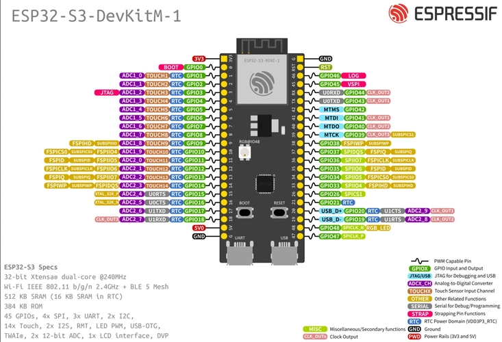
I looked in to the ESP-S3 and the ESP-C3 because they both have Wifi and Bluetooth modules, have many sensor pins
For the ESP-C3 I found the following 2 fabricators that already have breakout pins. The ESP-S3 has a single core processor Adafruit Wemos C3 Mini V2.1.0 - Lolin Wifi Iot- board ESP32-C3
ESP-S3
- note this is a dual core processor Xiao made a board for the
- Octopart see which chips (micro processors) are in stock Tinytronics for ordering microcontrollers and parts
- For ordering development boards and parts: Sparkfun Adafruit !
Languages
You need a programming language to talk to your micro controller. You can choose between many:
The language to speak to your programmer almost directly is called assembly code
| programming languages | explanation |
|---|---|
| HEX code | code that is actually going in in to the processor |
| Assembly languages | instead of numbers you write words and each word is an instruction in the instruction sheet |
| Inline assembly language | higher lever program with assembly instructions, fastest and most efficient programming language |
| C | higher level then assembly language, routine variables loops execute instructions one of the oldest higher level languages most common used, easy to make security mistakes easy to get data you should not see that hackers use. |
| C++ | extends C with objects making it more readable easier to use. Arduino as a language is based on C and C++ 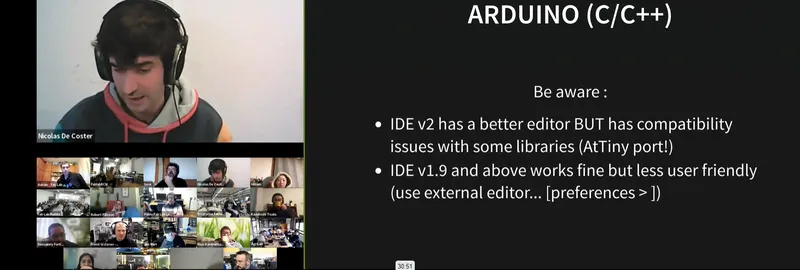 |
| GCC | open source project for compilers, takes your C program and turns it in to low level instructions the processor understands most of us you is behind arduino interface |
When working with the Arduino code, which uses a lot of libraries, make a note that these libraries does effect the following things, so you might need more or these things when choosing a micro chip:
RAM - uses more memory
Timer - libraries function needs one timer
Uart - often uses TX and RT pins for communication
ADC / DAC - libraries often use digital analog / analog digital converters that needs to be integrated on the chip.
| Newer programming languages | explanation |
|---|---|
| Rust | Rust much more recent strong safety. Compiled code helps to avoid mistakes |
| Go | more recent languages that prevent security mistakes |
Interpreters programming languages C is compiled, you write a program and it gets turned in to instructions for the processor. Python is interpreted, you write a highlevel language and one line at the time it turns it in to an interaction for the processor. It’s slower but in return it’s interactive. Powerful processors are fast enough to work with python languages so with the PR2040 you can do this!
| Interpreters programming languages | explanation |
|---|---|
| MicroPython | Based on python with added support for hardware, Benefit when programming is it’s more human to understand and send instruction to the chip with this Python based language |
| Circuit Python | spin-of from MicroPython Made by adafruit, easier to understand for beginners |
Compare workflows
Henk showed us how to code the blinking example with TinyGo when it worked I was not enthusiastic enough ;) . This was because I was already dizzy of all the new terms this day that it was hard for me to understand what he was doing at all. He programmed it in the terminal as Henk does. I already used the RP2040, arduino IDE and arduino language (based on C and C++) in the week 4 - electronics production with blinking a LED. I used the arduino Uno with my own capacity sensor for the final project using Arduino Uno and arduino IDE and arduino language here. So for the group assignment I try to do something completely new and use micro python language with PlatfromIO (PIO) and VSC. Together with Joany. This didn’t work so I ended up using MicroPython and Thonny and my RP2040 board.
The rest of the group worked on the following languages and IDE’s all using the RP2040:
- Leo work on Go language with VSC
- Joany and I tried out PIO visual studio code and MicroPython
- Joe work on arduino IDE with Arduino language based on C and C++
- Edwin tried Thonny and microPython and I ended up doing the same.
Platform IO IDE in Visual Studio Code with microPython
Arduino IDE
- great for beginners
- used to working with it now
- easy interface
- very good support
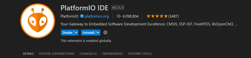
Platfrom IO IDE
- help solve code
- supports 800 development board
- auto complete
- if you use function make sure to put them at the start of the code.
- adding library;s is similar to arduino IDE
- library’s are saved inside the project .ini file
To try it out I start with downloading PlatformIO IDE by going to the extensions tab of the left side of the screen and install it.
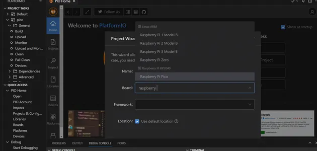
 On the home page I follow the get started and afterwards click on the ** + New Project** button and select the right board, I remembered from the electronics week when we set up our IDE that we had to select the Raspberry Pi Pico (Rasbery pi RP2040) board because is had the same chip as our board. So I do this again in PlatformIO
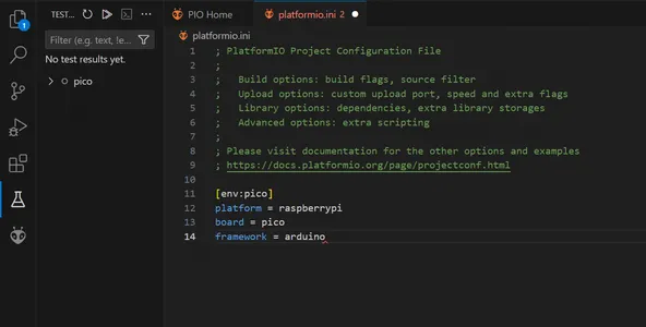
 The program makes this plaftomio.ini file with information about the board:
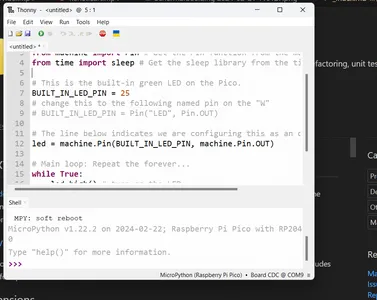
We looked up micro python blink code and found this code on coderdojo. I can understand that this is a more human understandable code since it starts with almost sentences. From machine import Pin and from time import sleep in the set-up code. working with constants is similar to the Arduino language Pin.OUT makes it an output pin and you can set a name or number with u use the = character. * delay * has changed into sleep.
# Setup - run once
from machine import Pin # Get the Pin function from the machine module.
from time import sleep # Get the sleep library from the time module.

# This is the built-in green LED on the Pico.
BUILT_IN_LED_PIN = 25
# change this to the following named pin on the "W"
# BUILT_IN_LED_PIN = Pin("LED", Pin.OUT)

# The line below indicates we are configuring this as an output (not input)
led = machine.Pin(BUILT_IN_LED_PIN, machine.Pin.OUT)

# Main loop: Repeat the forever...
while True:
    led.high() # turn on the LED
    sleep(0.5) # leave it on for 1/2 second
    led.low()  # Turn off the LED
    sleep(0.5) # leave it off for 1/2 second
Here I make my first mistake, I past the code underneath the .ini file and did not understand that I had to create a new file for this. Edwin helped me out and showed us we need the main.cpp file and past our code here. You can find the file in the menu on the left inside the src folder. We open this folder and paste if here. We try to build the code but run into tons of errors. PIO doesn’t seem to understand micropython. I try to keep following the tutorial and see that it’s using Thonny. At this moment I think I need Thonny to install the new bootloader on the chip so I keep following the tutorial and only later understand that Thonny is also an IDE. So I end up using Thonny and MicroPython for my test. Leo is helping out Joany and figure out that micropython is not supported by platfrom IO directly so they use PyMakr plugin to be able to use micropython in VSC. You can read about it in her documentation.
Thonny IDE with MicroPython
Install Thonny and follow this tutorial on the wiki page of the micro controller to get the chip to work with MicroPython and with help from Edwin.
I start with pressing the R and B to reset reset then unplugged the USB cable and plugged it in while holding the B (boot button) The drive will show like a USB stick and you can click and drag files on it.
In Edwin’s documentation i find the following steps:
go to index.htm site
go to https://www.raspberrypi.com/documentation/microcontrollers/micropython.html
download UF2 file (Raspberry Pi Pico, not the ‘W’)
drag and drop file to the drive
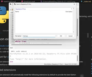
So I followed his documentation. The UF2 file is a bootloader and makes the micro chip able to work with the MicroPython language. I put in the same MicroPython code I tried in the PIO IDE but I put it in Thonny.
I save the code to the Raspberry Pi Pico as main.ply source and the LED is blinking!
I try out putting Arduino language in VSC PlatformIO to see how the workflow of PlatformIO is after all but I keep getting the same error number 1. Michelle said she had it so when she did Fabacademy and was working al day to figure it out. I read about is that you have like a 50/50 percent change of it working right away or you have this weird error number 1 error. The code compiles without problems finds the right USB COM, starts uploading it on the board but just doesn’t want to finish it and right before the end I get this Error number one over and over again. I leave it how it is for now and stop the search to fix this problem pretty quick I still have lots of other things I want to focus on this week.
I conclude that I have much to learn and I will stick with the Arduino IDE for now because this is already new for me, I just stared learning with the arduino basic samples. However the Thonny workflow was quit nice I had way more problems with the platform IO. But I don’t want to make it more difficult for myself right now so I will stick to the arduino language, libraries and IDE.
Individual assignment
For my final project i will try to read the input from the velostat sandwich pressure sensor I made last week that I document on the final project process week.
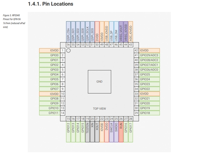
RP2040 I start with browsing through the data sheet but mostly the Seeed XIAO PR2040 wiki again to don’t mis important stuff and make some notes.
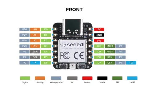
- The seeed XIAO RP2040 has 3 build in user LED’s and one neopixel on the board.
- The I/O pins work on 3.3V, you can damage the board when you put the GPIO pins to 5V incorrectly so watch out!
- The Seeed XIAO is a break out board with a Raspberry pi RP2040 chip so in the datasheet of the chip you can find all the functions of the chip. And in the wiki-page of the XIAO you can find the pins on the break out board. You I follow the Seeed documentation as a main lead.
Serial monitor - pressure sensor
To let the micro chip communicate to my computer I use the serial monitor when I use the Serial.print line of code the serial monitor will show me something. I typed ln behind it so it will make a new line making the communication more readable. In this case I want the monitor to show the sensorValue. a number between 0 and 1024 that shows the indicates the resistance of the velostat and changes when pressed. I used Adrian’s sample code of the Flexure Sensor. At first I didn’t alter anything. I start without using the map function to see what my sensorValue is without pressing it. It’s around the number of 500. If I press it really hard it goes up to 1200. and I then mapped it form 0 to 50
//Fab Academy 2021 - Fab Lab León
//Textile Flexure Sensor
//Adrianino
//ATtiny1614
int sensorPin = 28;    // analog input pin to hook the sensor to
int sensorValue = 0;  // variable to store the value coming from the sensor
int ledPin = 25


void setup() {
  Serial.begin(115200); // initialize serial communications
}

void loop() {
  sensorValue = analogRead(sensorPin); // read the value from the sensor
  sensorValue = map(sensorValue, 500, 1024, 0, 50); //I change the sensorValue values to make an map that is more readable
  Serial.println(sensorValue); // print value to Serial Monitor
  //mySerial.println("x"); // print value "x" to Serial Monitor
  delay(1000); // short delay so we can actually see the numbers
}
Neopixel - Rainbow sample
- I followed this tutorial to try out the Neopixel on the XIAO RP2040. To be able to work with the Neo Pixel on the board I start with installing the library Adafruit NeoPixel by Adafruit in the arduino IDE environment. I follow this seeed Wiki tutorial about Neo pixels with the PR2040. It uses Pin 11 to power the LED and pin 12 as an output pin. I will use the rainbow example of the tutorial without altering anything to see if the pixel will work.
#include <Adafruit_NeoPixel.h>

int Power = 11;
int PIN  = 12;
#define NUMPIXELS 1

Adafruit_NeoPixel pixels(NUMPIXELS, PIN, NEO_GRB + NEO_KHZ800) ;


void setup() {
  pixels.begin();
  pinMode(Power,OUTPUT);
  digitalWrite(Power, HIGH);

}

void loop() {
  pixels.clear();
  pixels.setPixelColor(0, pixels.Color(15, 25, 205));
  delay(400);
  pixels.show();
  pixels.clear();
  pixels.setPixelColor(0, pixels.Color(103, 25, 205));
  delay(400);
  pixels.show();
  pixels.clear();
  pixels.setPixelColor(0, pixels.Color(233, 242, 205));
  delay(400);
  pixels.show();
  pixels.clear();
  pixels.setPixelColor(0, pixels.Color(233, 23, 23));
  delay(400);
  pixels.show();
  pixels.clear();
  pixels.setPixelColor(0, pixels.Color(12, 66, 101));
  delay(400);
  pixels.show();
  delay(500);

}
If else statement - Velostat input and Neopixel output
- I combined both codes I used before by using an If else statement Not fully understanding the Neopixels functions I use Chat GPT to help me explain I typed the following prompt:
User
help me explain this code:
pixels.show(); // put the pixel on
pixels.clear();
pixels.setPixelColor(0, pixels.Color(15, 25, 205)); // color purple
- I used the described answers for the explanations in my own words in the code below. I will now try to use input of the flex sensor to make the neopixel change color. So I use the map function to change the output numbers from 0,1024 to 0, 50. And I test the code. The code works but the response is super slow. I delete the delays in the code and only put one at the end to read my serial monitor numbers.
// this code reads a Velostat sensor and turns it in to colored NeoPixel
// it's based on the Textile Flexure Sensor documentation code of the Adrianino Fab Academy 2021 - Fab Lab León and the Seeed studion NeoPixel example code.
// Edited by Vera Schepers with an if else statement

#include <Adafruit_NeoPixel.h>
int sensorPin = 28;    // analog input pin to hook the sensor to
int sensorValue = 0;  // variable to store the value coming from the sensor
int ledPin = 25 ; // analog pin 25 to read sensor value from

int Power = 11; //  sets power to pin 11 this is a General Purpuse Input Output pin
int PIN  = 12; // swdio pin, this is the pin that receives data
#define NUMPIXELS 1 // I use 1 neopixel

Adafruit_NeoPixel pixels(NUMPIXELS, PIN, NEO_GRB + NEO_KHZ800); // sets number of led's output pin color mode green red blue

void setup() { // code that runs one time at the start
  Serial.begin(115200); // initialize serial communications

  pixels.begin(); // initialize led's
  pinMode(Power,OUTPUT); // set's LED pinmode to output
  digitalWrite(Power, HIGH); // set's power to high to probebly overwrite the default LOW settings on this pin.
}

void loop() {
    sensorValue = analogRead(sensorPin); // read the value from the sensor
  sensorValue = map(sensorValue, 0, 1024, 0, 50); //I change the sensorValue from 0,1024 to 1, 50 so it's more easy to read the value's

if (sensorValue < 25) { // if the sensor value digit is smaller than 25
   // update the library to the new data, show shows the right color mostly used after setting the colors for the pixels
  pixels.clear(); // clears the pixel color and turns off all the LED
  pixels.setPixelColor(0, pixels.Color(15, 25, 205)); // the number 0 referce to the index of the pixel 0 refence to the first pixel (only one in this example)
  pixels.show();
  //the three numbers make the color (red, green, blue)
  //Altogether, these three lines of code first update the LED strip with any changes made, then clear all the pixels (turn them off), and finally set the color of the first pixel to purple
} else {

  pixels.clear();
  pixels.setPixelColor(0, pixels.Color(233, 23, 23));
  pixels.show();
}
   Serial.println(sensorValue); // print value to Serial Monitor
  //mySerial.println("x"); // print value "x" to Serial Monitor
  delay(100); // short delay so we can actually see the numbersdelay(200);
}- The code works nicely. I add the else if statement giving me a 3th option and I add Serial.println(“Sensor Value”) So the code will be more readable.
//

#include <Adafruit_NeoPixel.h>
int sensorPin = 28;    // analog input pin to hook the sensor to
int sensorValue = 0;  // variable to store the value coming from the sensor
int ledPin = 25 ;

int Power = 11; // sets power to pin 11 this is a General Purpuse Input Output pin
int PIN  = 12; // swdio pin
#define NUMPIXELS 1

Adafruit_NeoPixel pixels(NUMPIXELS, PIN, NEO_GRB + NEO_KHZ800);

void setup() {
  Serial.begin(115200); // initialize serial communications

  pixels.begin(); // initialize pixel communications
  pinMode(Power,OUTPUT); // setting pinmode to an output
  digitalWrite(Power, HIGH); // setting the pin to high meaning ON

}

void loop() {
    sensorValue = analogRead(sensorPin); // read the value from the sensor
  sensorValue = map(sensorValue, 0, 1024, 0, 50); //I change the sensorValue from 0,1024 to 1, 50 so it's more easy to read the value's

if (sensorValue <= 28 ) { // if the sensor value digit is smaller than 25 do this

  pixels.clear(); // clears the pixel color and turns off all the LED
  pixels.setPixelColor(0, pixels.Color(15, 25, 205)); // color blue the number 0 referce to the index of the pixel 0 refence to the first pixel (only one in this example)
  pixels.show(); // update the library to the new data, show shows the right color mostly used after setting the colors for the pixels, the three numbers make the color (red, green, blue)
  //Altogether, these three lines of code first update the LED strip with any changes made, then clear all the pixels (turn them off), and finally set the color of the first pixel to purple
  Serial.println("Sensor Value Blue"); // print this text to the serial monitor to make it more readable
  Serial.println(sensorValue); // print value to Serial Monitor
}
else if (sensorValue > 28 && sensorValue < 43) { // else if the sensor value is bigger then 25 and smaller then 41 do this
  pixels.clear();
  pixels.setPixelColor(0, pixels.Color(233, 23, 23)); // color red
  pixels.show();
  Serial.println("Sensor Value Red"); // print this text to the serial monitor to make it more readable
  Serial.println(sensorValue); // print value to Serial Monitor
}
else { // else so it the value if different from the previous things do this
  pixels.clear();
  pixels.setPixelColor(0, pixels.Color(23, 233, 23)); // color green
  pixels.show();
  Serial.println("Sensor Value Green"); // print this text to the serial monitor to make it more readable
  Serial.println(sensorValue); // print value to Serial Monitor
}


delay(100); // short delay so we can actually see the numbers
}
Dim the LED - Velostat input and Neopixel output
- I also tried to dim the light using the setBrightness function from the adafruit neopixel liberary The brightness is an Integer between 0 and 255. So I use the map function again to map the Sensor Value from 500 - 1024 To 0 and 255. I reused a lot of code from the samples above and it works nicely.
  #include <Adafruit_NeoPixel.h>
int sensorPin = 28;    // analog input pin to hook the sensor to
int sensorValue = 0;  // variable to store the value coming from the sensor
int ledPin = 25 ;

int Power = 11; //  sets power to pin 11 this is a General Purpuse Input Output pin
int PIN  = 12; // swdio pin, this is the pin that receives data
#define NUMPIXELS 1

Adafruit_NeoPixel pixels(NUMPIXELS, PIN, NEO_GRB + NEO_KHZ800);

void setup() {
  // put your setup code here, to run once:
  Serial.begin(115200); // initialize serial communications
  pixels.begin(); // initialize pixel communications
  pinMode(Power,OUTPUT); // setting pinmode to an output
  digitalWrite(Power, HIGH); // setting the pin to high meaning ON because this pin is default low so no power

}


void loop() {
  // put your main code here, to run repeatedly:

sensorValue = analogRead(sensorPin); // read the value from the sensor
sensorValue = map(sensorValue, 500, 1024, 0, 255); //I change the sensorValue from 0,1024 to 0, 50 so it's more easy to read the value's
Serial.println("Sensor Value"); // print this text to the serial monitor to make it more readable put this close to the actual reading
Serial.println(sensorValue); // print value to Serial Monitor
pixels.clear(); // clears the pixel color and turns off all the LED
pixels.setPixelColor(0, pixels.Color(205, 205, 205)); // color blue the number 0 referce to the index of the pixel 0 refence to the first pixel (only one in this example)
pixels.setBrightness(abs(sensorValue));// absolute means it can not be a minusvalue
pixels.show(); // update the library to the new data, show shows the right color mostly used after setting the colors for the pixels, the three numbers make the color (red, green, blue)
  //Altogether, these three lines of code first update the LED strip with any changes made, then clear all the pixels (turn them off), and finally set the color of the first pixel to purple

 delay(200);
}- I did run into an error. The sensor is sometimes reading negative values. And It turns the LED to the high (brightest ) then. I try so alter the mapping a little bit, but can’t fix the problem. I end up writing the abs function before the sensorvalue so it can only be absolute numbers, I got the tip from a college. I this the problem is that the threads on the sensor are soldered on the same side with the velostat between them and the thickness of the solder make the mapping fluctuate a lot. I will remake the sensor making sure both threads and on another side and have no velostat on the end part I think it will really help the mapping.
Reflection
This week I spend A lot of time on making my lecture notes readable and understand it. I had so many new terms that I couldn’t place and understand. It was only at the end of the week that I started programming. I really enjoyed seeing something work! Wished I had more time for it. I did learn a lot but a lot of things don’t really make sense to me still especially the different communication modules and electrical circuits. Hope to get more familiar with it soon.