3D scanning and printing
intro
Goal for this week is to check up the present 3D printers and test / characterise these printers (and printer-software-filament combinations). For checking design rules (overhang, tolerances,). The design we opt for is the bengine which can test / probe the following characteristics of a 3D printer. Besides printing a lot of ‘bengines’ I like to continue to work on my final project - AND get some other print and scan processes underway.
Full Furby Face as Print In Place
Group assignment:
- Test the design rules for your 3D printer(s)
- Document your work on the group work page and reflect on your individual page what you learned about characteristics of your printer(s)
Individual assignment:
- Design and 3D print an object (small, few cm3, limited by printer time) that could not be easily made subtractively
- 3D scan an object (and optionally print it)
lab demos at Waag
In the lab the current set of machines and tools is available for exploration. The current inventory:
- modified Ender as biomaterials printer (with extruder)
- a working Ultimaker 2+. A non-working ready to be converted Ultimaker 2+
- a voron 2.4 (diy) large format printer
- an Elegoo Mars 3 resin printer
- A Prusa i3-Mk3S
- An Ender 3 (prusia i3 clone)
- A sainsmart belt printer
demo: direct G-code
Demo by code-to-design expert Bas Pijls who showed us his work on generating g-code directly from software (in this case made with processing.org). For Fabacademy he used an ender 3 as printer, today we use an Ultimaker 2+. The machine accepts g-code allright, but for some reason cannot handle comments in g-code.
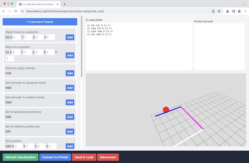
Webtool for direct g-code compiling and sending
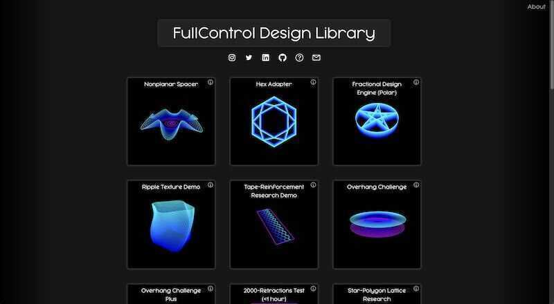
Fullcontrol.xyz - a website / project with parametric designs generating gcode directly.
As tool to send g-code you can use the Arduino IDE terminal (serial monitor) at 250000 baud (for an Ultimaker 2+) or a web tool which Bas designed and used as part of his Fabacademy work. You need to use a chromium based browser because of webserial. The following example contains g-code and some explanatory comments:
G28                  ; home
M104 S200            ; extruder temperature
M190 S60             ; print bed temperature (with wait)
G90                  ; absolute coordinates
M83                  ; relative extrusion
G1 F1000             ; set feedrate in mm/sec
G0 X10 Y10 Z0.1      ; travel - in mm

G1 X10 Y10 Z0.1 E2   ; extrude (with relative extrusion distance)
G1 X100 Y10 Z0.1 E2  ; extrude (with relative extrusion distance)
G1 X100 Y100 Z0.1 E2 ; extrude (with relative extrusion distance)
G1 X10 Y100 Z0.1 E2  ; extrude (with relative extrusion distance)
The E-setting (extrusion lenght) is tricky: how many mm per action which can be absolute or relative. The latter is used most (an M83 code in the top of the code is a sign that relative code is used. For calculating the length of an extruded section you can use pythagoras (E = sqrt((x-previous_x)^2+ (y-previous_y)^2))
In order to prevent buffer overflow with the used serial terminal, it might be better to use an SD-card. The results of Bas are very impressive!
demo: biomaterial printing
Not used for our benchy test, but interesting to watch. A project by Laura @ Waag: printing with biomaterials. Currently a mixture of corn starch and pulped egg carton, mcc (cellulose powder), glycerin and water, sunflower seed oil and vinegar (as preservative), kurkuma (for colour).
Laura uses a modified Ender3 with a (previously open source) design of an extruder system by ReflexLab. In the control settings it is important to
- prevent cold extrusion, either in firmware or in G-code control
- use a large nozzle size (currently 2mm)
- use pronterface (or other direct G-code tool) to send g-code
- prime the extruder, so make sure to have plenty of paper around because things can get messy….

Laura's bioprint setup

design shown in pronterface
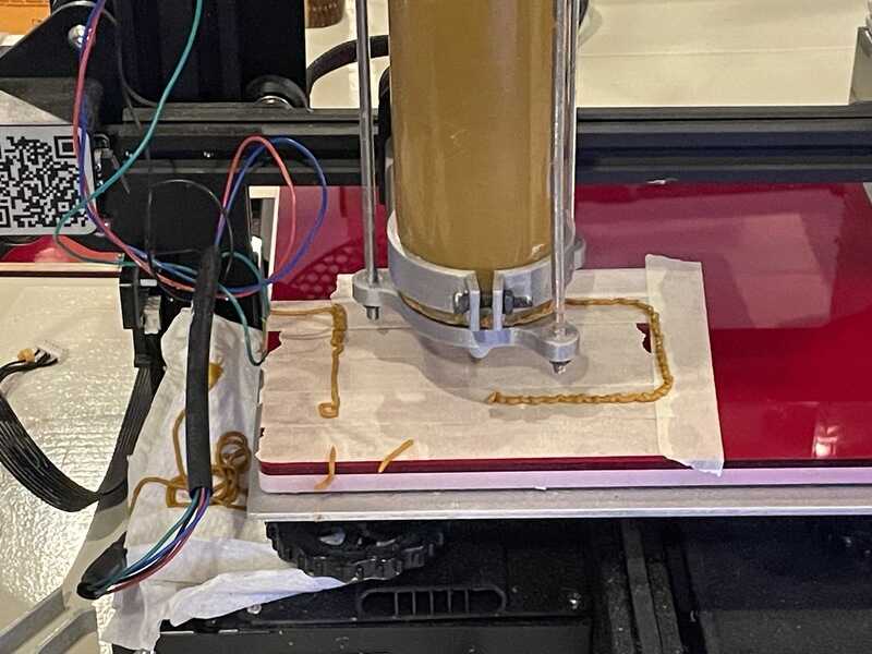
first lines of box drawing

final product - before drying
first lines of a biomaterial design print
scanning
The scanner in use is a Crealty CR-Scan Ferret. It comes with software ‘Crealty Scan’. During the session a full-body scan of Leo is tried. The software is installed from this link. Manual can be found here
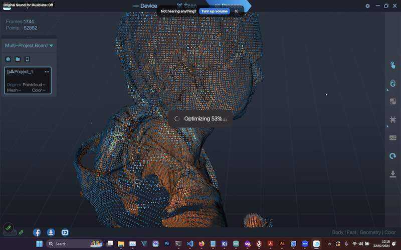
Scan of Leo-with-coffee-cup processed in Crealty SCAN

Processor and GPU power consumption for processing the data
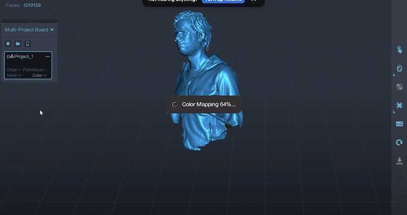
mapping process
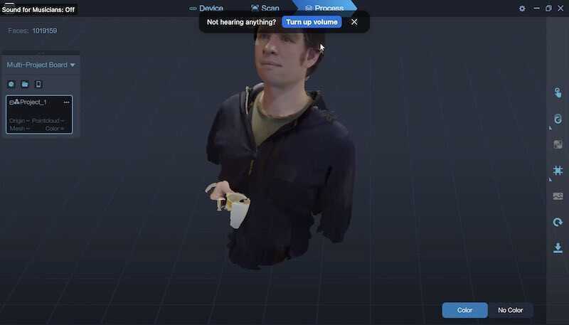
colour added
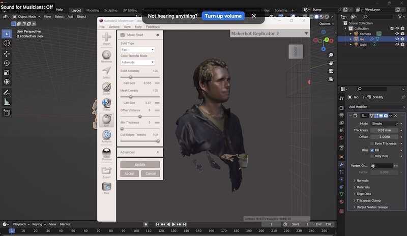
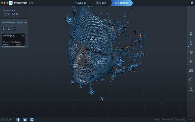
processing the scan in blender
A quick check in portrait mode results in the following (face front). It is nice to see how the software already removes part of the artefacts
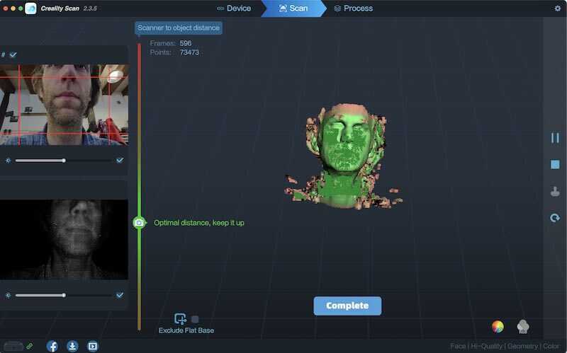
scanning my face in 'face-scan mode
scan of my face
group assingment
intro
Goal of this weeks group assignment is to test printer capabilities. We opt for a standard printer-torture project, the follow up on the well known benchy: the bengine which can test / probe the following characteristics of a 3D printer.
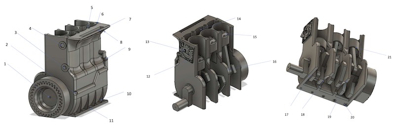
bengine printer torture design
- 0.7mm channel through crankshaft
- 1.2mm channel to cooling chamber
- 1mm hole in vertical plane
- 0.3mm Embossed hex
- 1mm hole in horizontal plane
- 0.5mm hole in horizontal plane
- 20mm Bridging
- Freestanding overhang
- Freestanding pipe
- Thin ribs
- 0.5mm holes close to build surface
- 0.86mm embossment at 5deg
- Detailed embossment
- Cooling chamber/internal surfaces
- Valve pockets / Vertical resolution
- Radius
- Warping test
- Arching overhang (10mm Radius)
- Bed adhesion
- Elephant footing test (base hole 0.5mm, chamfering: 0.8mm, 0.5mm, 0.3mm, 0.1mm, 0mm)
Since we are interested in how different filaments (in combination with different printers in our lab) behave, we opt for an approach where we used the same printer settings (as much as possible) while using different filaments (and getting things to work)
- factory default (slicer) (cura, creality ender, prusa slicer, bambulabs)
- stock settings
- 0.4 nozzle
- 0.15 layer height
- no support
- brim only when needed
- 20% infil, grid pattern
- normal retraction (so only when strictly necessary turn off with bowden printers and flexible filament)
Ultimaker 2+
One of the older Dutch workhorses at the Waag (and also present in my homelab). Print works after 3 attempts:
- bed levelling, apparently a bit too high
- clean buildplate with alcohol, go again
- bed leveling a bit tighter. (Everything to prevent having to use a brim).
Settings are basically the standard settings in Cura (recent version 5.6.0 on macOS) Material used is grey PLA/PHA filament by colorfabb, processing temperature 190-210 degrees.
- inspiration to try with cura -> custom infil option download new
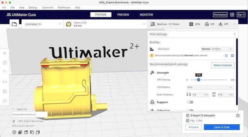
bengine in Cura
start in the ultimaker
first misprint

successful print
bengine in grey PLA
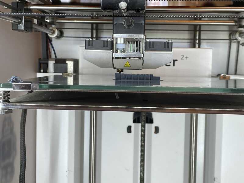
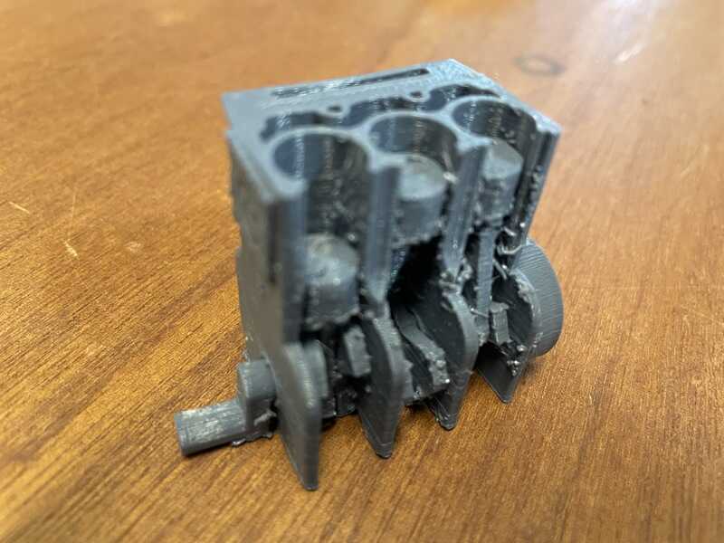
Prusa i3-Mk3s
Also a work horse in the small 2-printer printfarm. The printer is enclosed in a standard IKEA lack enclosure with lighting and a smoke detector. Filmanent is stored in a SUNLU active dry-box set at 49 degrees.
Filament used is PETG from prusa (Prusament PETG, orange, 1.75 mm, 240-260 deg. 70-90 printbed)
Slicing is done using prusa slicer (2.7.1). - prusa slicer -> plane cut-off download fresh
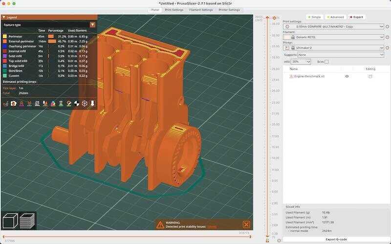
bengine in prusa-slicer
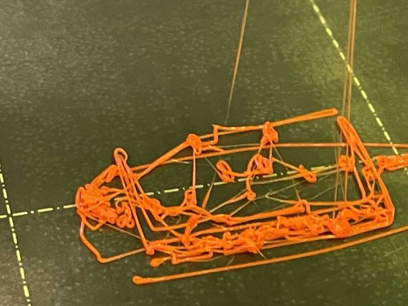
spaghetti
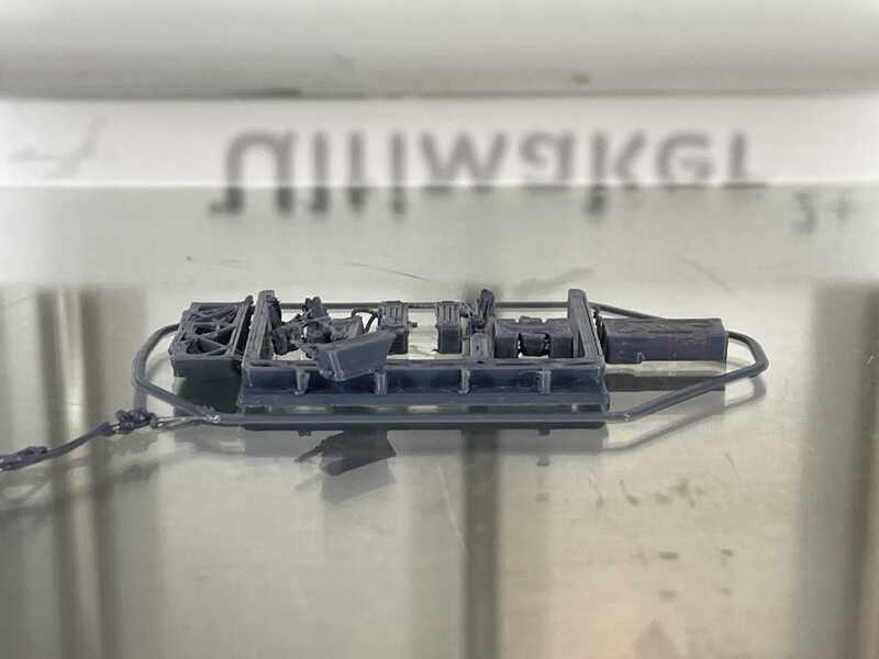
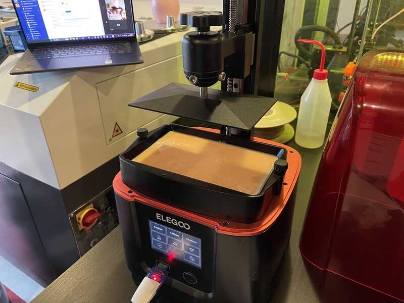
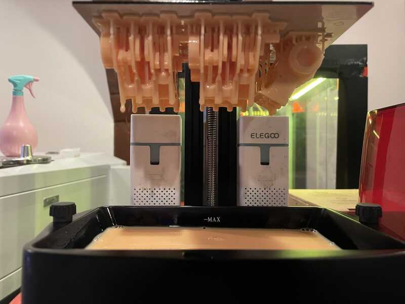
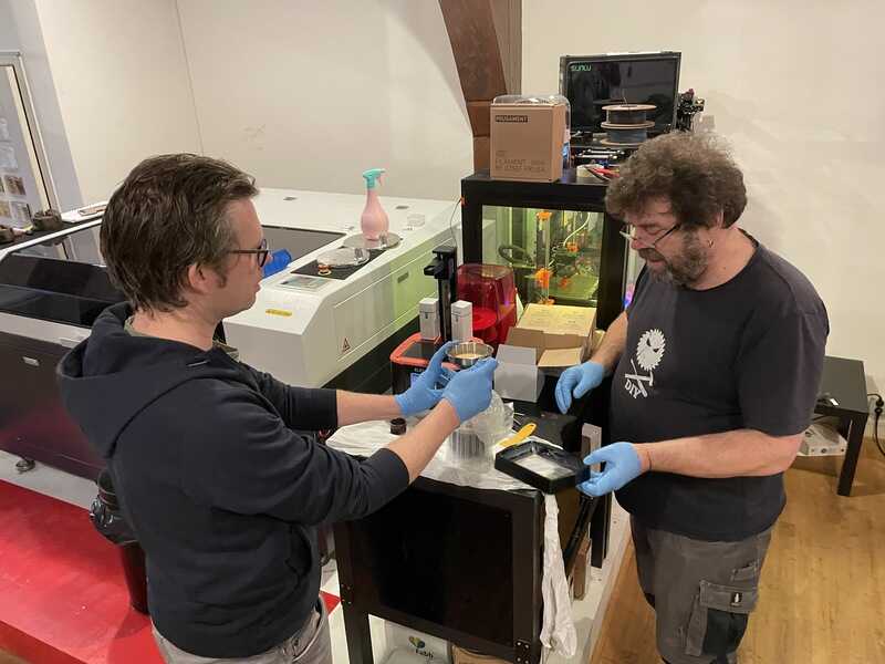
elegoo mars 3 sla printer
This printer uses UV curing liquid (standard beige photopolymer resin). Slicing is done using Chitubox 1.9.5. In this program the designs are placed and sticking support is added. The support looks like tree-support used in cura and prusa slicer - the idea is to put the designs a bit above the build plate, under an angle, in order to avoid ’elephant feed’ - a wide sticking bit that is needed to make sure your design sticks to the build plate, which can become an uninted addition to your design.
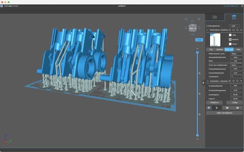
Slicing and build-plate configuration in Chitubox
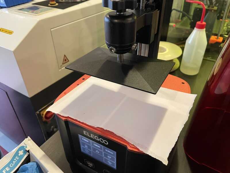
setting the build plate to its zero position
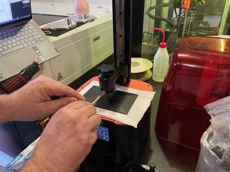
using an allen key
Henk mixing his favourite mojito
turns out a bit yellow to my taste
mapping process
colour added
mapping process
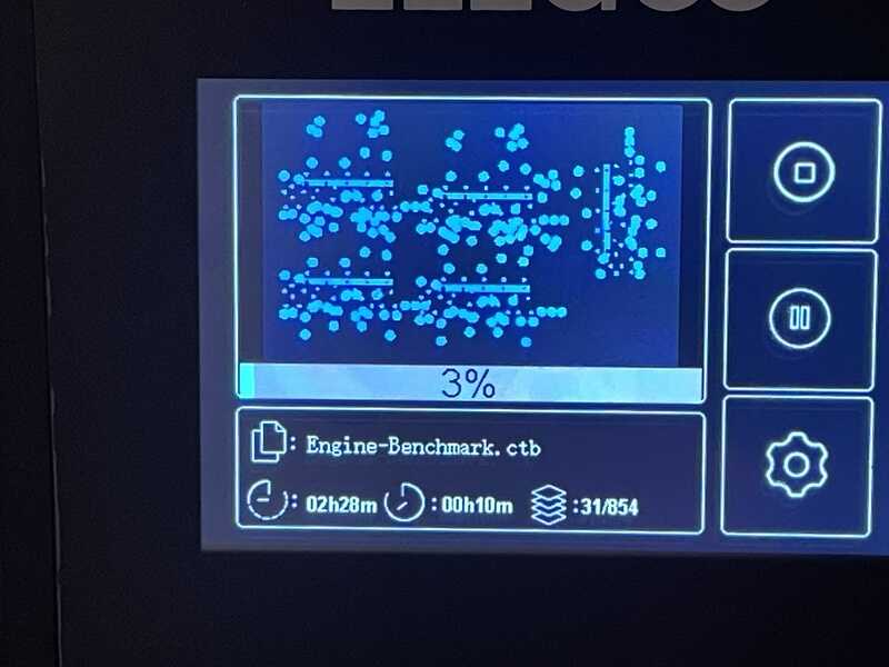
timelapse of elegoo at work
In the video with the elegoo at work you see the effect where it moves the printbed down for the illumination sequence, and subsequently up a bit for curing / soaking / resting.

UV ligth on for 1 sec
UV image of one of the layers
-
using chitibox sla slicer
-
needs fume extractor (portable)
-
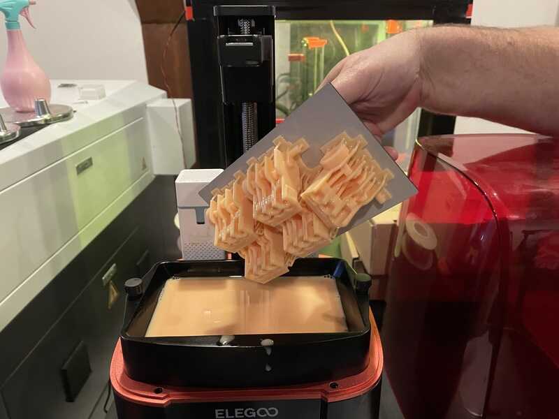
henk prepared 5 engines in one go
-
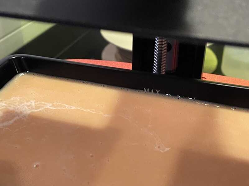
liquid in machine (max level)
-
start print job
-
after print is done (2hrs) : rinse in alcohol (5 min)
-
after alcohol, leave to dry (no more alchol)
-
post curing in UV machine (Elegoo Mercury Plus)
-
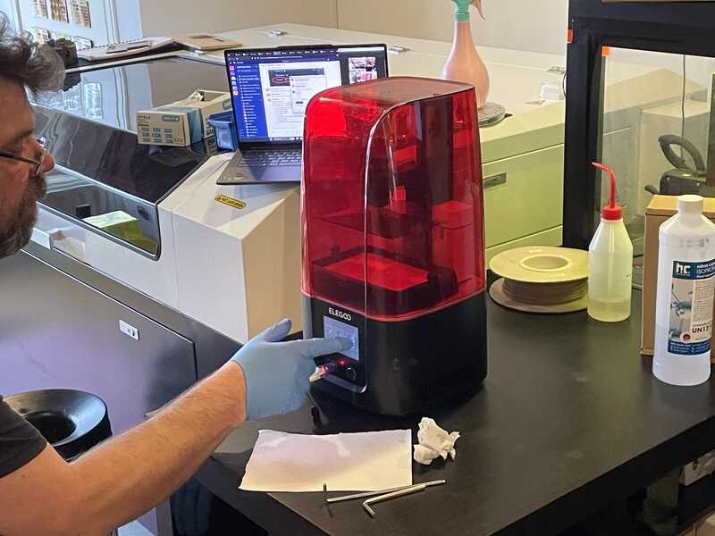
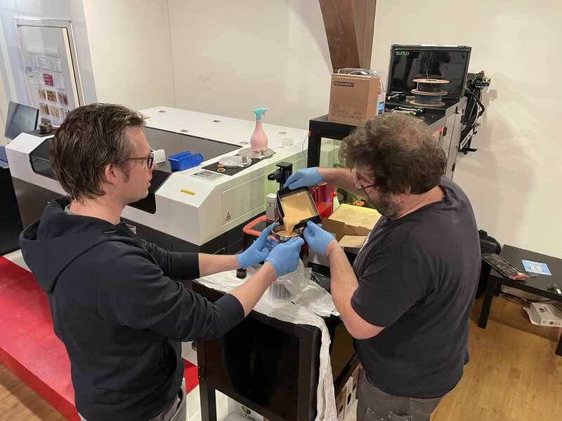
extensive (!) cleaning of all parts used
elegoo ready
taking the bed out of the machine
removing the print from the bed
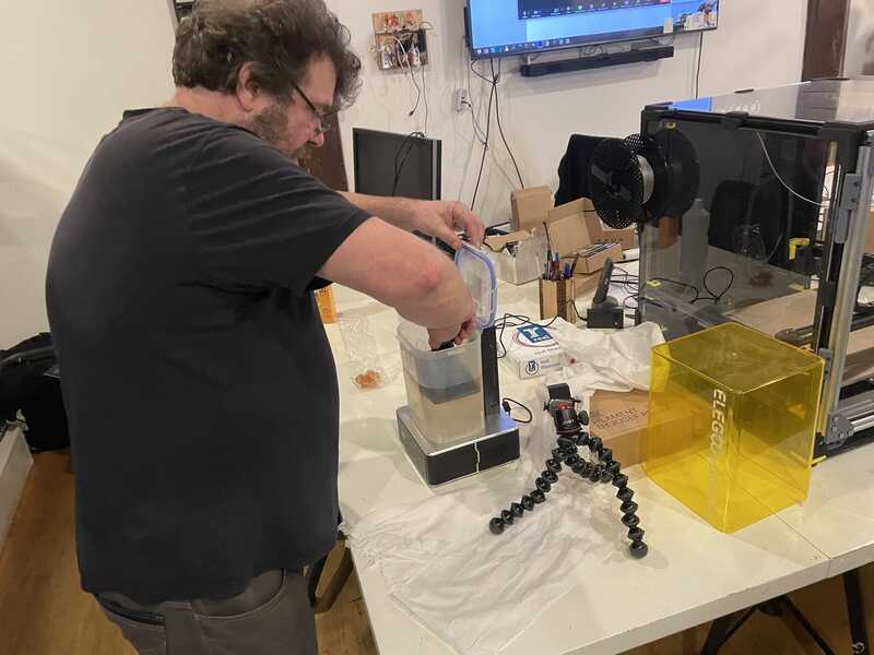
putting the print in an alcohol bath
cleaning the elegoo goo
reclaiming unused resin
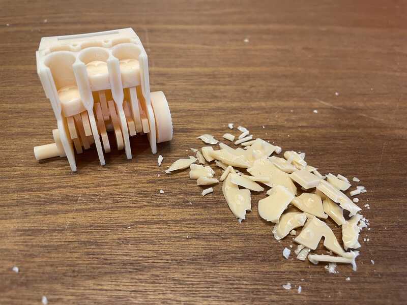
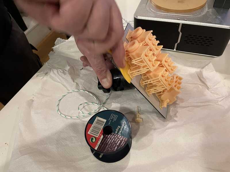
cleaning up resin support
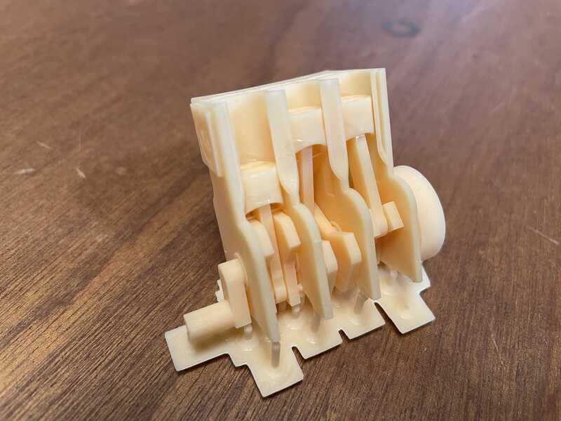
resin print with support
eventually the resin print moves!
voron 2.4 design - large bed machine
The voron is an impressive machine based on an open source design. Large format FDM with many bells and whistles. As it is, it neede calibrating - we have not been able to use it in action, although Henk proudly demonstrated its gantry-levelling system. Also the videos of follow up designs were very impressive:
- insanely fast version coming up next https://docs.vzbot.org/
Voron printer
automatic gantry leveling
printer tests
Further printer tests in the home lab and FabLab Oldenzaal. In Oldenzaal I tried the BambuLab Carbon X1 and for comparison a very old Vertex Nano (Velleman K8300). In the home lab I ran some tests on the resident Ultimaker 2+, a converted Velleman K8200 with Cerambot upgrade - and ‘Scrapth’ - a printer combination build using Ender, Anet, Prusa and random extrusion profile parts.
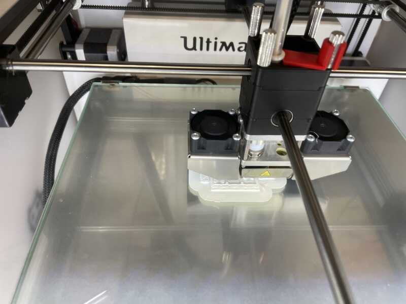
Ultimaker 2+
First up as reference some standard (easy) material: white PLA from a reasonably fresh roll (less than a few months old). Using standard settings and slicer config
- white PLA single pass (0.4 mm nozzle. single go) 60 mm/s
standard white PLA
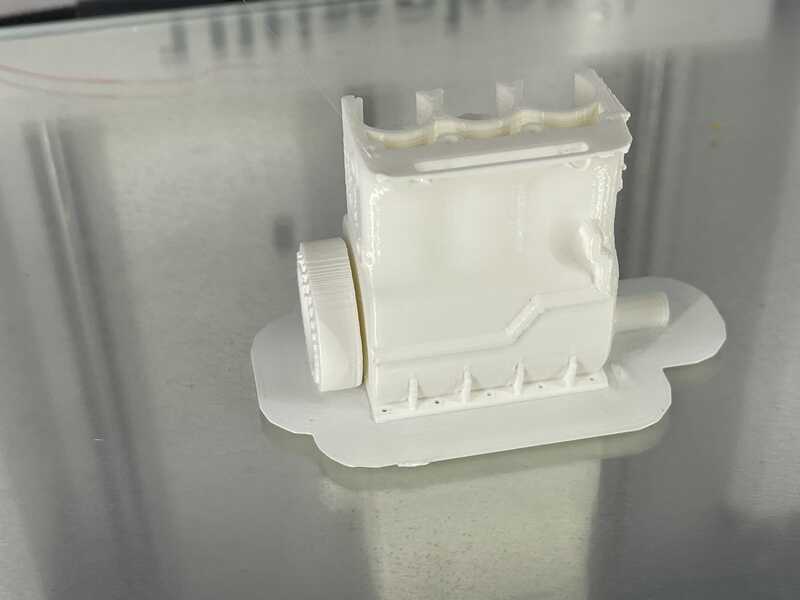
completed bengine
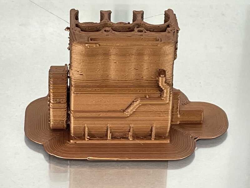
- copper filament (0.6) - single go - 40 mm/s

Ultimaker printing (rather old) PLA with copper filament
nice result from one side

copper bengine, not too much stringing, poor inter-layer adhesion
For this print I had to slow down the printer a bit and used a different nozzle. The 0.4 mm would not print at all, so I went for 0.6. Print time was exactly the same (so 40mm/s at a 0.6 nozzle equals 60mm/s at a 0.4 nozzle :) Eventually the bengine does not move, but details, layers and overhang are quite ok.
- wood filament 0.6 mm 3 mm high (nozzle clogged)
- 0.8 mm 10 mm high (clogged nozzle)
- 0.8 mm, 30 min 70 deg oven 40mm (clogged nozzle)
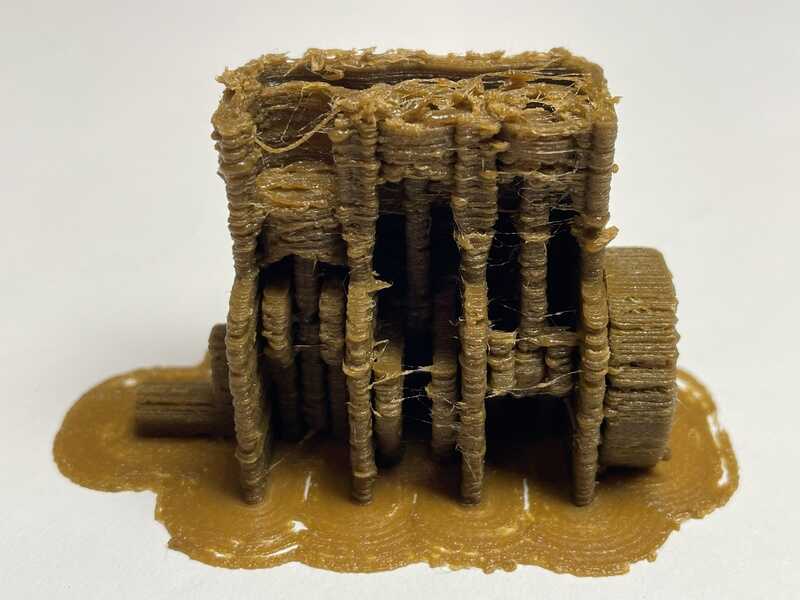
best result with wood filament
drying wood in oven, 30 min, 70 deg
silver glitter (0.6) 6. complete (lot of stringing)
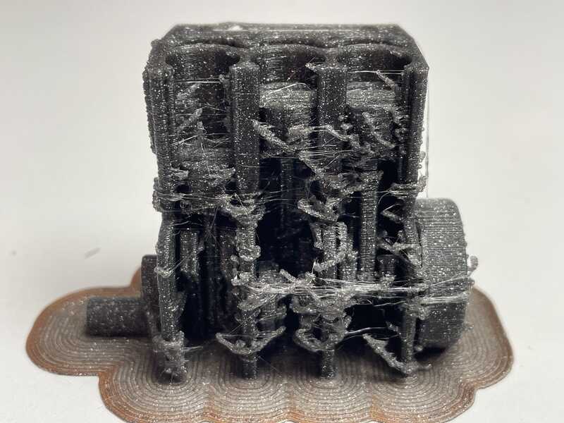
Grey glitter PLA, printed with 0.6 mm nozzle. Too much stringing, so in need of revitalisation
PETG red transparent (0.4) 7. complete - lot of stringing.

red transparent PETG. lot of stringing
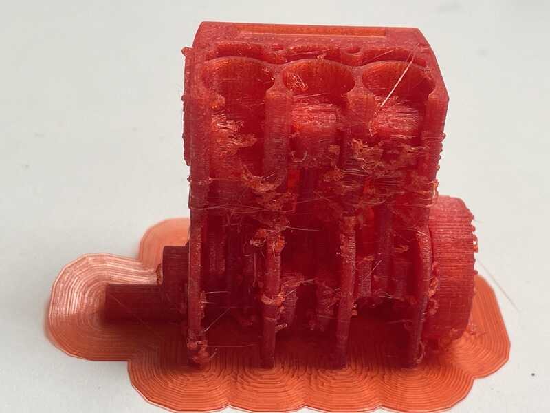
red PETG bengine

less pretty side of the red bengine
in conclusion: more often nozzle change for rought filaments. A heated filament box might help with older filaments.
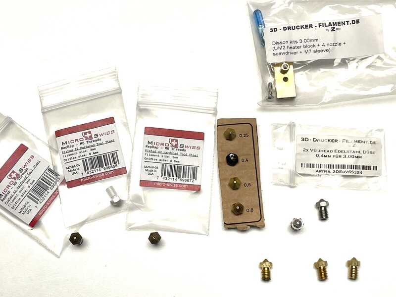
different nozzles, also a parameter to change and worth considering
BambuLab
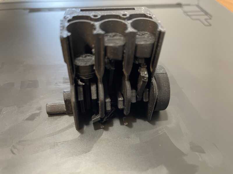
black matte PLA. one go (0.4 mm, )
printed with eSUN black matte PLA, 1.75 mm print tem 190-230 bed temp 45-60 fan 100
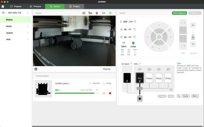
preparing print job in bambu studio
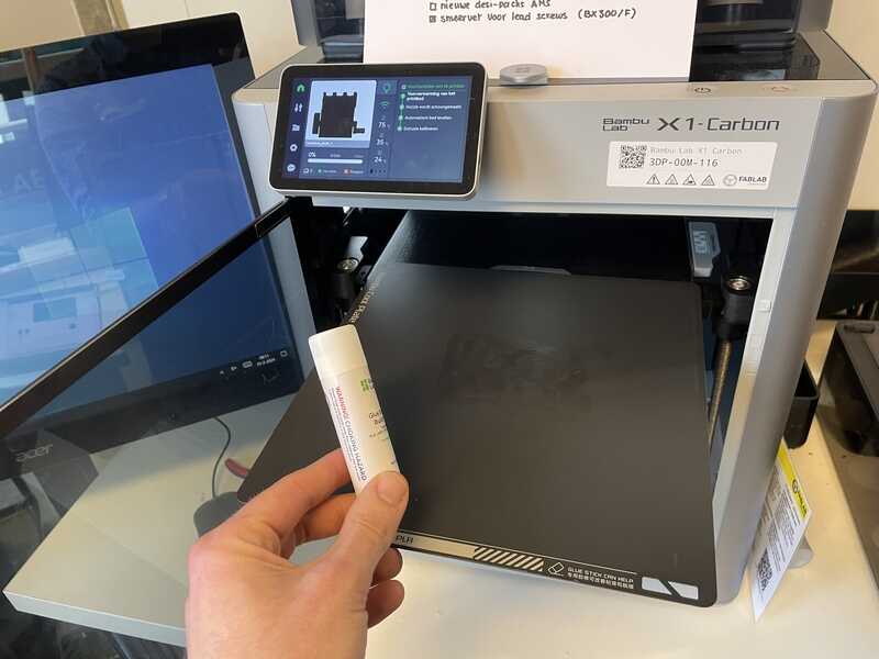
prepare build plate (gluestick)
printing
finalised print
Vertex Nano
The vertex nano (or K8600) is one of our ‘old’ printers - It is a very small FDM module with an 8 x 8 x 8 cm build volume. It is not in daily use - but we kept it out of nostalgia. The original slicer (Repetier) is no longer available, so I used cura (made a profile for generic FFM printer)

cura slicer settings for vertex
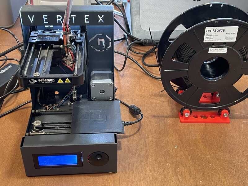
Vertex (K8600) with 1.75 mm filament spool
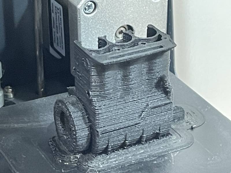
resulting bengine
The end result is quite brittle and did not come of the buildplate whole. The exterior features, overhang and brige look quite ok.
conclusion
The following series of bengines was printed, along with the bengines printed by Vera, Joe and Leo
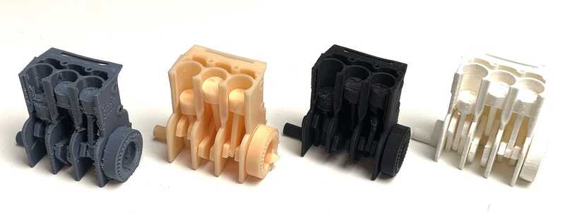
First series of bengines

second series of bengines
Based on this experience I take the following insights as keep-home-messages:
- wood filament is very difficult
- you can play with nozzle diameter quite easiy
- filament condition is very relevant (brittle, stringing)
- printer conditioning helps (door, cabinet)
Leo, Vera and Joe arrived at similar conclusions:
- Vera had working bengine (moving) using PLA on the Bambulab
- PLA, PET and lightweight PLA on the Ultimaker were not working in her case
- Leo printed with PLA, PC, ABS and PETG and only got a moving result with PETG (and PLA somewhat). He also reported ok-ish PLA on Bambu (but with brim) and did most of the other work on the Ultimaker 2+ too.
So, an adiditonal (unwanted) conclusion - based on our Dutch research - when the chips are down, all of us need to fall back on the trusty Ultimaker 2+. Despite all the fantastic Prusa, Voron, Bambu and competitive tech….. :)
individual assignment
intro
First (ambitious) goals:
- print a clay furby based on scan
- print a (print in place) version of the furby face modeled in week 2
- print something using direct control on an experimental frankenstein machine
Scanning
The idea is to scan a Furby, and use it as basis for a vase (mug) design printed on the ceramic printer
Ciclop
First attempt: open Scan (horus) - mesh is far from complete and useable. The scanner used is an open source cyclop this site with software (horus) running on a WIN10 machine.

Ciclop open source scanner
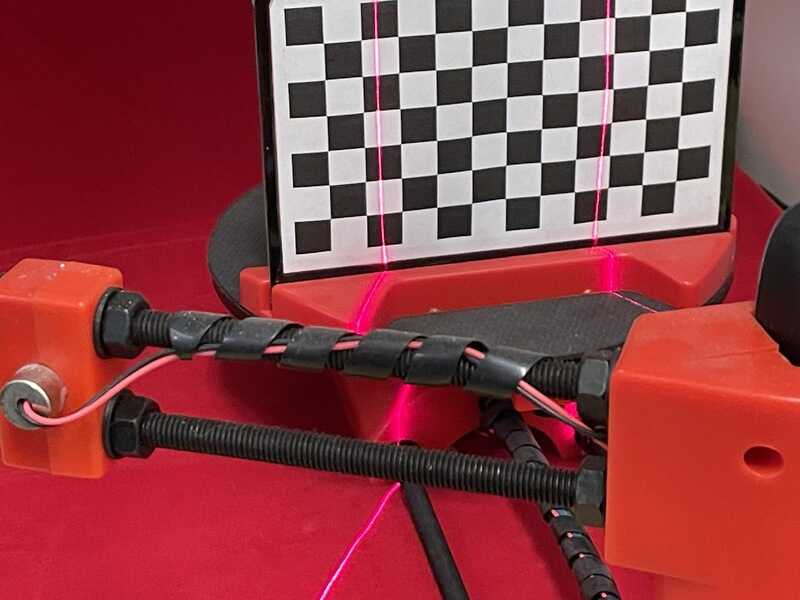
calibration using pattern
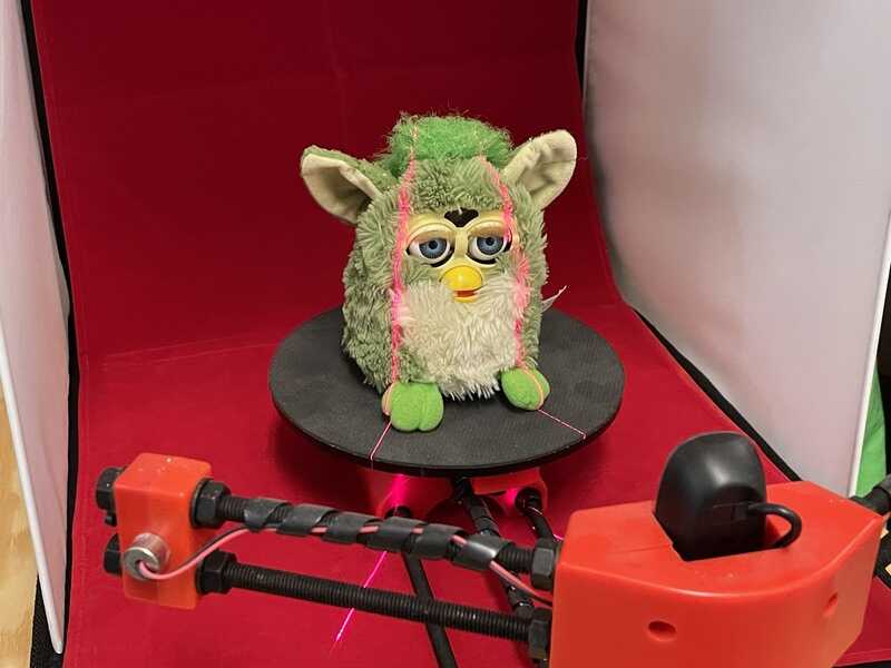
furby on the scanner

resulting scan in horus
furby being scanned
furby scan result
Crealty Scan Ferret SE
- much trouble with pluchy hair
- needs many steps (and time) of re-work in blender. Timeboxed at 2 hours. Not succesful, Blender tutorials help, but not much. The approach (stitching, or solid offsetting or using a differnt shape ‘shrunk down) - I lack experience and time to make this work for now. Tried this:
https://www.instructables.com/Clean-up-a-3D-Scan-using-Blender/
managed to clean and allign the scan, but stopped at the exterior shape modelling.
Option B- use an existing furby model: https://www.thingiverse.com/thing:4776004
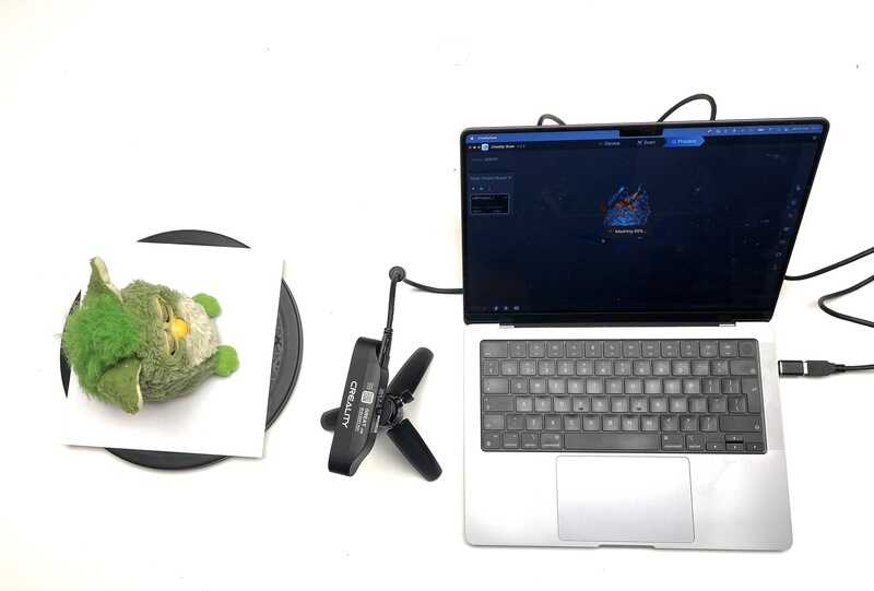
crealty scan setup
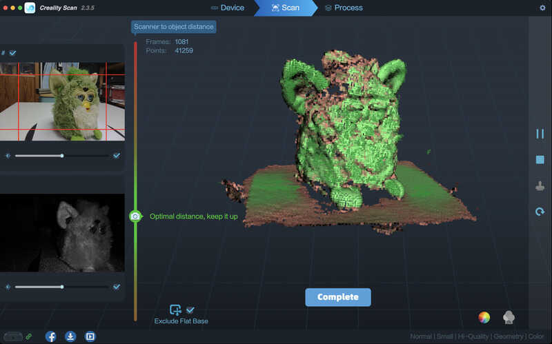
CrealtyScan software
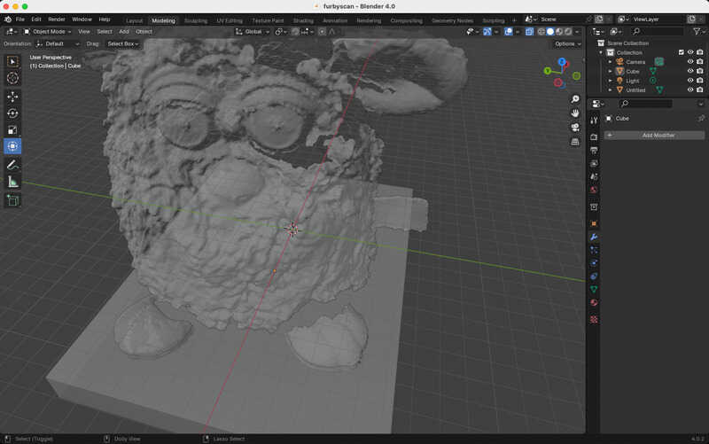
Data imported and cleaned in blender
clay printing
Goal print a furby mug. Or a furby garden gnome!
The printer is a modified K8200 by Velleman with a Cerambot clay extruder.
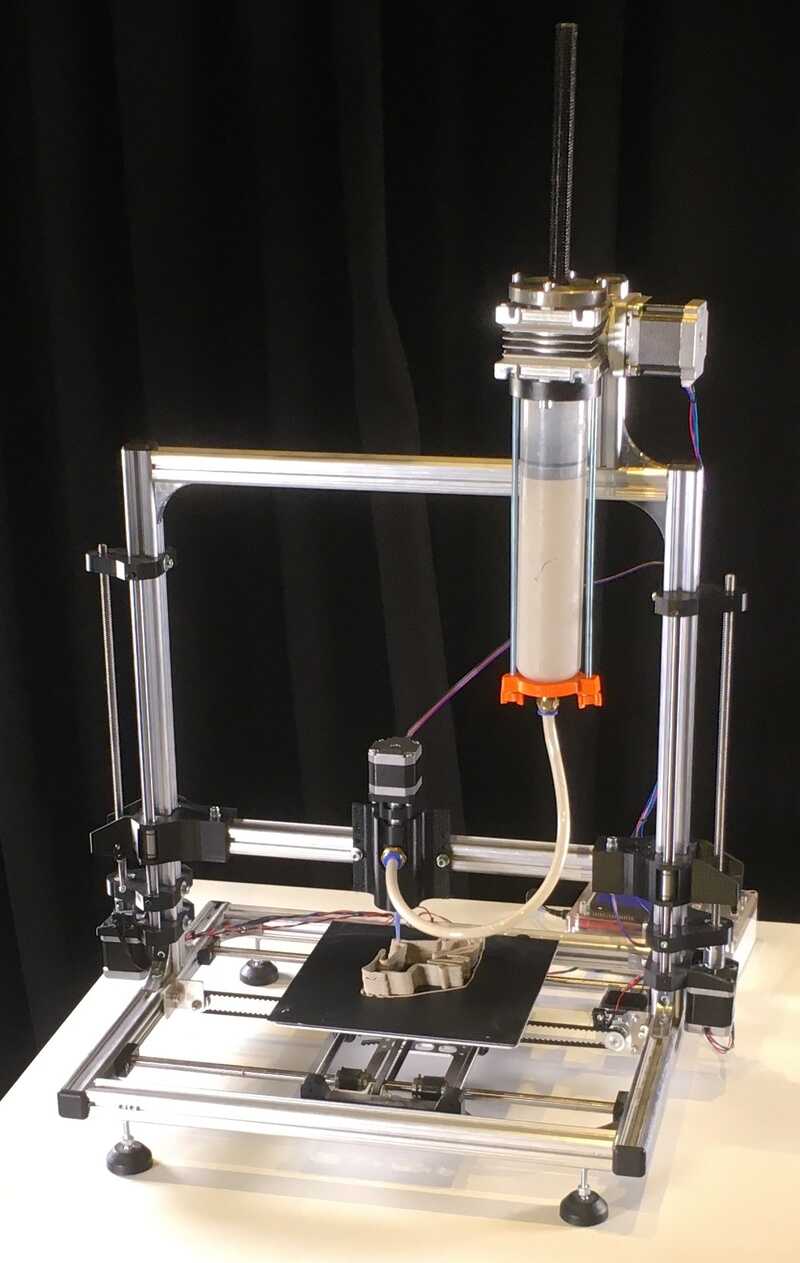
K8200 + Cerambot
- prepare clay: 50ml at 500g, ziplock,

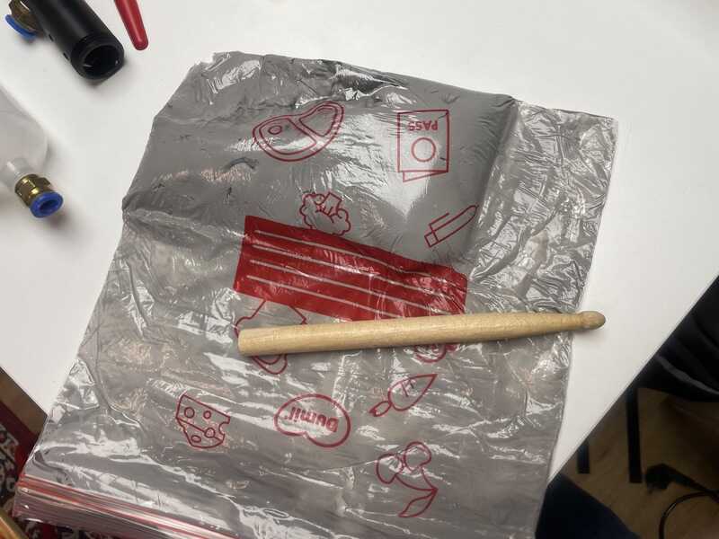
tools
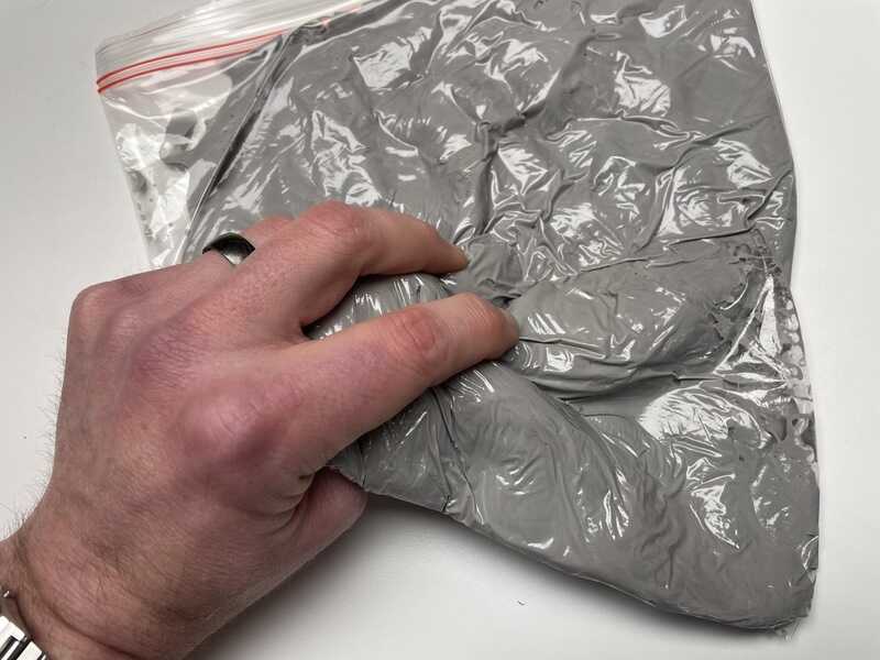
preparing (kneading) the clay in ziplock bag

self hardening clay as material
preparing for squirt
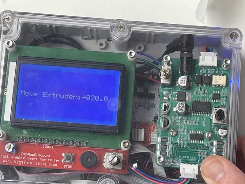
manual control on the box to prime the auger and set ratio to 50%/50%

install filled plunger in place
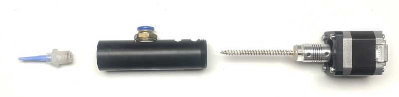
cleaned auger components ready for install
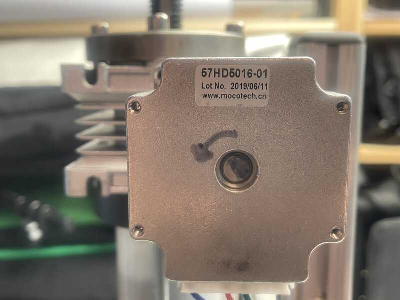
checking motor direction
check if clay is moving
filling the auger
- use ultimaker settings: spiral outer, use brim. width 1.2 mm, slow (10 mm/s)
- set mixer rate at 50% / 50%
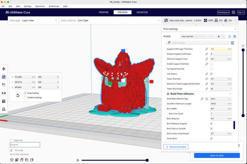
cura slicer settings for furby

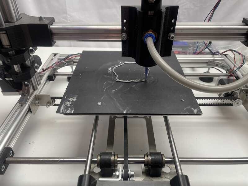
priming the nozzle
furby feet
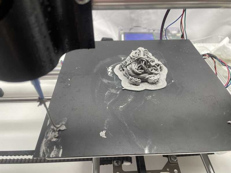
collapsed furby after layer 20
furby feet
collapsed furby after layer 20
The following print attempts were made
- furby design - fail at first layer: extrusion settings not right, reduce steps/mm for extruder
- furby design - fail at layer 10: collapse. might have something todo with layer and most of all: overhang
- vase - fail at layer 5: under extrusion. Although a 2mm thick string is extruded the balance between layer height, compressing and extrusion rate is not ok.
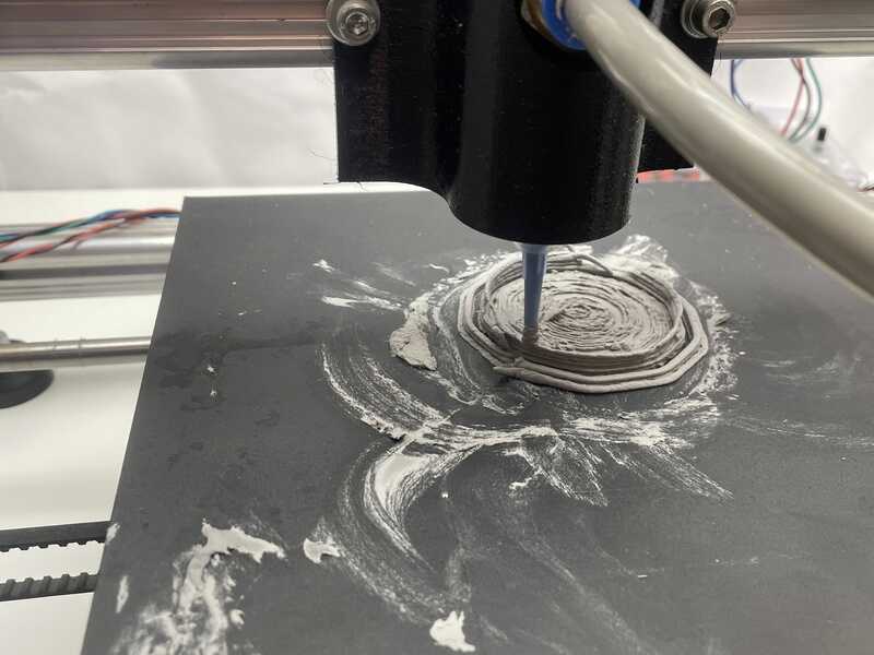
start of a different design
conclusion
Clay printing requires more work. Initial pieces prior to the furby attempt came out quite ok, but the displacement per layer was very small. A furby might come out as garden gnome (with infil) instead of as vase. For next iterations I might need to change the clay-water ratio, although that is something not easily fixed on the fly. Also the extrusion rate, length, diameter and other aspects might need more testing and calibration for further work. For now the settings (diameter, extrusion length) seem to match ok, but the resulting prints are not good enough yet.
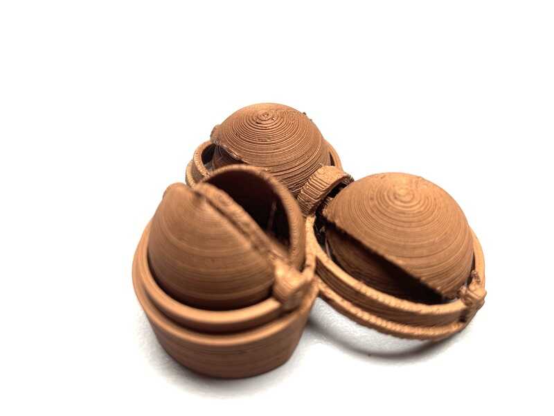
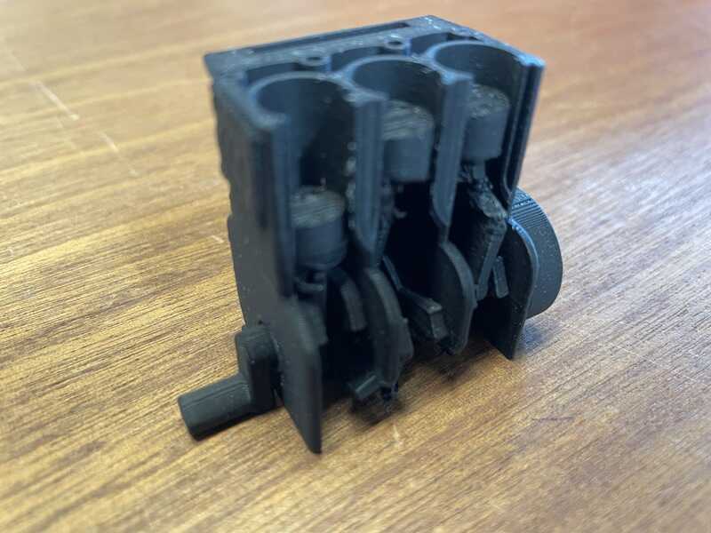
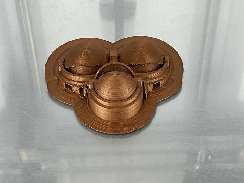
print-in-place test of furby eyes
Based on the idea of a print of a design that cannot be produced otherwise, I loved the idea of print-in-place, like the bengine test models. The idea here is to use the openscad model directly and print in copper PLA filament. The end results looks stunishing (like han-solo-in-carbonite). Eyes can move a bit, beak is solid, so more attention needs to be put in shaft, diameters and rotation points.
In OpenSCAD I added aditional tolerance for the shaft, so the rotating parts have a highter diameter cutout, the shaft uses the same diameter.
The updated OpenSCAD file can be found here
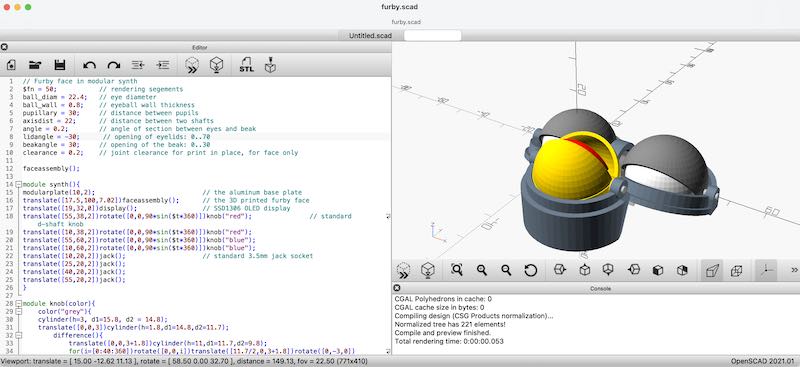
OpenSCAD design for only the furbyface

face sliced in cura
face on printbed
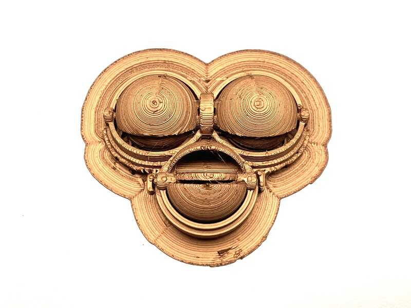
face is ready

support removed
I tried some settings for the shaft, but I’m afraid the 2mm horizontal shaft in the design is a show-stopper. The Bengines also use larger diameter hole (and inserted piece). For the final version I probably still need to resort to a model printed component by component.
Many of the shapes needed are eventually still impossible to manufacture using substractive manufacturing. Still, for next projects involving mechanisms I will definitely look more into options for print-in-place.
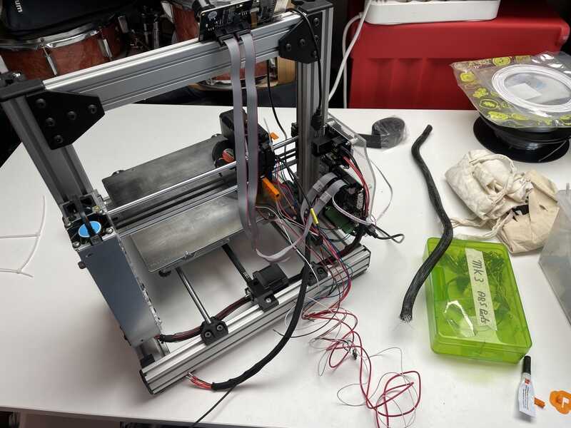
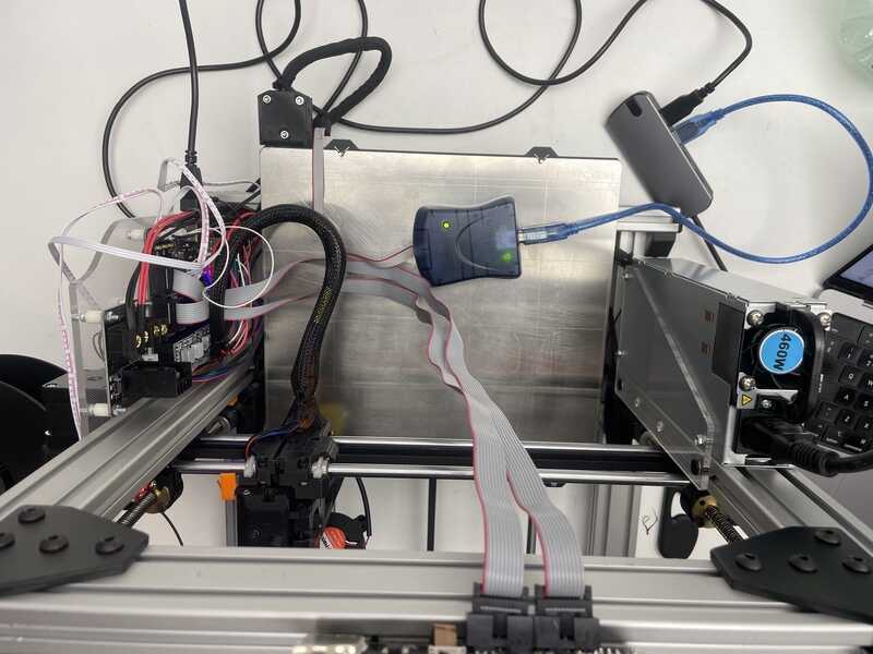
direct G-control
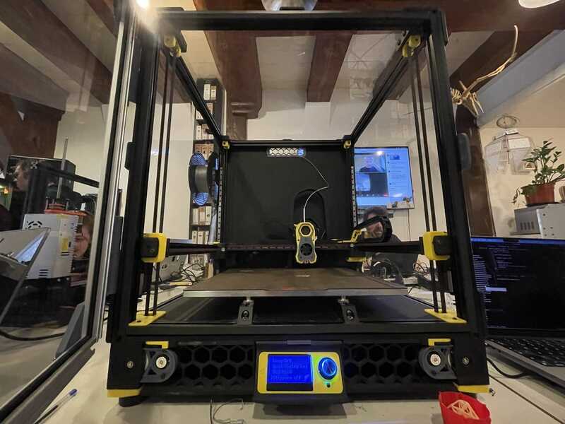
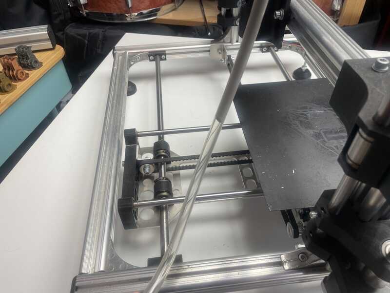
Since I don’t want to risk ruining the Ultimaker 2+ which I also use as my reliable work-horse in the workshop, I used this opportunity to complete the assembly of a printer built from Scraps… (so, why not call it ‘Scrapth’ (read ‘Carpe Jugulum’ by Terry Pratchett) It uses
- bearings, rod stock, motors from an Anet
- a prusa heated printbed
- a bigtreetech control board with drv8835 drivers
- a bigtreetech LCD display controller
- an Ender 12V extruder
- 12V power supply from a stock HP server
- optical end stops
- bear prusa frame and bear prusa (i3 MKS) brackets and parts that have been altered to fit a different aluminum extrusion profile
- no filament sensor, no automatic bed levelling
Mounting end stops, crimping sockets

calibrating end stops
The bits that need finishing this week:
- mounting end stops (3 x optical end stop, manufacturing mounting pieces, crimping sockets)
- wiring the steppers: uniform colour coding: A-A+ B-B+ (red, blue, green, black)
- attaching cables
- configuring firmware:
- second Z-axis motor
- heatbed
- homing directions
- fans
- checking extruder, homing, calibrating
using the AVR-ISP instead of the (non working) bootloader
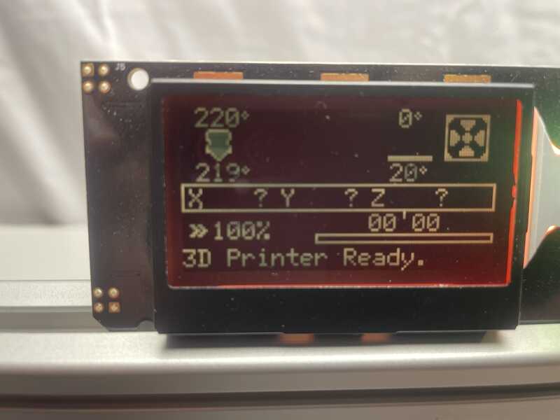
first sign of life, all ready to go
I used Marlin Version 2.0.9.5 (download a fresh copy) and used VScode to edit the files. For VScode there is an ‘Auto Build Marlin’ extension which adds two buttons: for compilation and for uploading. All other parts for actual configuration are not working (yet).
In my case the used board (KFB2.0) for some reason refused to make bootloader connection (might have something to do with resetting and the WHC340 serial adapter and drivers) so I used an AVR-ISP-MK2 to program the board (yes, I know ISP is since Bootcamp week something of the past, but when in need any tool might do. I can’t believe somone going “now we have this automatic press device, hammers are really something of the past”. My trusty AVR-ISP is a hammer) I used the VScode / Platform.io part to compile and build the code and subsequently used avrdude to flash the firmware.
avrdude -c avrispmkii -p m2560 -P usb -U flash:w:firmware.hex
(note that chatGTP gives accurate instructions for using avrdude. Instructions for Marlin are not up-to-date)
In the end I used a separate install of avrdude using homebrew. It is possible to use the avrdude that is shipped with your Arduino install, but you have to add that folder to your path environment or cd into a deep, deep directory….
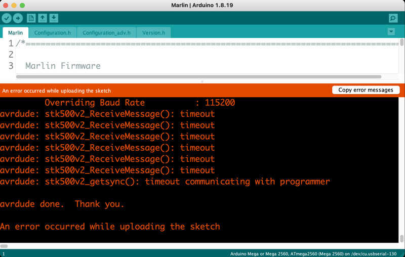
Arduino not compiling

avrdude with VScode does work
Configuring Marlin is complex because the developers have gone out of their ways of making it very smart. Instead of a setting #define USE_HEAT_BED (1) it will assume you use a heat-bed as soon as you have set a #define TEMP_SENSOR_BED 1 - where 1 signifies a specific type of sensor. Easy when you know, hard to find in the config file. THe following settings were changed with respect to the out-of-the-box config:
// in configuration.h / configuration_adv.ha
#define MOTHERBOARD BOARD_KFB_2 // the used BQ/Bigtreetech motherboard
#define Z2_DRIVER_TYPE A4988 // this enables the second stepper driver on E1 for Z
#define E0_DRIVER_TYPE A4988 // this is the extruder
#define EXTRUDERS 1

#define TEMP_SENSOR_0 1  // extruder
#define TEMP_SENSOR_BED 1 // this enables the heated bed

#define SDSUPPORT
#define REVERSE_ENCODER_DIRECTION

#define DEFAULT_AXIS_STEPS_PER_UNIT   { 80, 80, 400, 140 } // the last one was changed

#define FYSETC_MINI_12864_2_1 // for the display control unit
With M104 S220 and G01 E100 F100 the output of the extruder is tested. Subsequently the extrusion multiplier (steps/mm for the extruder) is adjusted from 500 to 140.
The machine is up-and-running, heat bed and extruder seem to heat up as they should, homing works. First set the crude Z-offset by moving the optical end switch, next up do a paper-friction-below-the-nozzle at the four courners of the bed repeatedly. The 10mm acrylic bed is still rather flexible, so the first upgrade will be metal Y carriage.
After a number of tests with Z-levelling I still don’t manage to get proper layer adhesion. This might have something to do with the filament age, used buildplate, flatness of the buildplate - etc.
So, although direct G-code control has been very convenient for setting up the printer, I have not have a chance yet to try out differently generated (non-sliced, direct) code.
Since the bed adhesion is very poor, I might have to install a bed levelling sensor, also since the bed is probably not completely flat. This can be configured in marlin
learning outcomes
- Identify the advantages and limitations of 3D printing
- Apply design methods and production processes to show your understanding of 3D printing.
- Demonstrate how scanning technology can be used to digitize object(s)
evaluation checklist
The task list for this first week (for personal reference)
- Linked to the group assignment page (again, reffered here on page)
- Explained what you learned from testing the 3D printers
- Documented how you designed and 3D printed your object and explained why it could not be easily made subtractively
- Documented how you scanned an object
- Included your original design files for 3D printing
- Included your hero shots
lessons learned, tips and tricks
(or, the most insightful mistakes I made)
- nozzle diameter is something to actively change on the fly - especially for specials. going to 0.6mm is something you can do without sacrificing too much print quality
- filament aeging (and conditioning) are very (most) relevant (note to self: get a filament heater)
- direct g-control: power to the people!!! Very convenient for printer operation and maintenance. Also node that the special moves (wiping nozzles etc..) are usually the pre-coded sections slicers add per-printer
- for scanning: mesh fixing tools need to be acquired (like blender skills). There is no ’easy fix’.
- for printing in place: vertical joints are good. horizontal joints mean trouble!
- portfolio system: also added a vscode snippet and key binding for image columns. Hit ctrl-space and type ‘imgcolumn’, next entry with tab
- portfolio system: renewed short-code for video, also added a caption to video inputs
left for todo
- check out sketchpad.io for quick doodles
- also check out https://en.openscan.eu/
- See also the google collab for fullcontrol.xyz
- build the IKEA lack table printer enclosure
- explore pause at layer: (or split file)? to put in magnets
- through-the-interface.typecad.com ? variable density 3D print gcode
- check out new gradient infil
- I used https://marlinfw.org/ - it might be good to check https://www.klipper3d.org/ as alternative
- gcode bending
- mesh fixing: meshlab, meshmixer, blender (especially more proficiency in the latter would be good)
reflection
This topic has been anounced as one offering a great deal of room for creativity. I think I learned a lot, but it was definitly not a week in which I felt my inner artist has been able to shine.
(I am also a bit in two minds about the ‘‘Nadieh - effect’’. Showing the perfect end result or showing a fantastic portfolio can be inspiring, but at the same time also very demotivating. The work Bas showed at Waag had a slightyly similar effect - very nice, creative, spiraling work - and also a huge investment of time - and very hard to live up to.)
Anyway, I tried a lot of things - dived into the nitty gritty of bed leveling, calibration, printer firmware and g-code. Cleaned a lot of ceramics, watched furbies collapse, many, many failed prints, clogged nozzles etc. It was nice to start working with scanner (and getting stuck on Blender). I liked the notion of printing in place - prompted by the bengine tests. It was difficult to balance the (re)design of my end project version with the eventual actuation (motors, tendons) needed.
copyrights and references
- no additional work used or quoted