Week 5
3D Scanning and Printing
Organizing
checklist
| group assignments | — |
|---|---|
| Test the design rules for your 3D printer(s) | |
| Document your work on the group work page and reflect on your individual page what you learned about characteristics of your printer(s) |
| individual assignments | — |
|---|---|
| Design and 3D print an object (small, few cm3, limited by printer time) that could not be easily made subtractively | |
| 3D scan an object (and optionally print it) |
Experience At the Fablab Arnhem I work daily with 3D printers and I made design rules and slicing posters for our UltimakerS5 and Formlabs machine for our students after doing test prints for our machines some time ago at work:
This week I want to focus on in-place printing (never did this before). And also in week 2 I didn’t find the time to explore Make mechanics work: joints, assemble goal with was on my list so I want to do this for the 3D printing week by designing and printing my own gears. For the group assignment we will try to print with different types of material and focus on this. I also have used the labs 3D scanners before. I’m not sure yet what I want to scan. Changing g-code for printing weird wavy things is also on my wish list especially combined with clay printing.
| learning goals | — |
|---|---|
| 3D design of a ball joint in-place printing | |
| Print a new material | |
| kinetic art inspired and 3D printed gear thingy | |
| Explore Full controll g-code editing | |
| 3D scan lens?? | |
| — | order mills |
| document on project page |
Instructions at Waag
Unfortunately I got a sore throat and got a bit sick this week so I decide to stay home this thursday to have a bit more rest, not having to travel to Amsterdam. At Waag they made a set-up so I could follow the program online. That was really nice of them! After installing a proper audio system I could hear everybody well enough to follow most of the conversations!
G-code editing
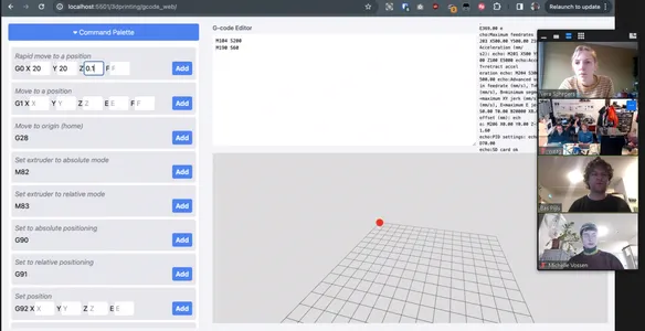 We start the morning with a workshop of Bas about making your own G-code to print something. It’s something i’ve heard about and are interested in but never did something with. Bas shows his work from wen he did the Fabacadmey which is very inspiring and looks like something I can so to. Especially when using the interface he made and the and the fullcontrol web interface to create g-code based on python. I definitely want to try this my self.
Bas tells us the most important G code settings:
| code | Function | sample code | notes |
|---|---|---|---|
| G28 | Home the machine | G28 | |
| M104 | Extruder temperature | M104 S200 | doesn’t wait until the next commando |
| M190 | Bed temperature | M190 S60 | waits until the next commando |
| G90 | Set absolute position | G90 | |
| M83 | Set extruder to relative mode | M83 | |
| G0 | Travel without extrusion | G0 X10 Y10 Z0.1 | |
| G1 | Travel with extrusion | G1 X10 Y10 Z0.1 E1 F1000 | |
| E | material per mm | Extrusion can be relative or absolute | |
| F | Travel speed of the head of the printer | F1000 | relies on how much material you extrude. |
Absolute position is always calculated from the home position Relative position calculates from the previous position of the head of the machine.
Bas show us how to make a box He has a few tips:
- You have to change the E (extrusion on the material) always because it depends on the segment.
- You can calculate the size of a segment when you know the two coordinates of the segment. Using Pythagorean theorem to calculate the length of the segment.
- Totally different way of thinking about 3D models, when using a slicer the think about making slices now you could think of a long thread and you decide when the thread is within time and space.
- You can make wave movements using sinus calculations.
I tried it with my Ultimaker S2Extended at home, but nervous of breaking something I started with just the home position. I connected my computer with the USB cable and first had some trouble with connecting. The problem was that I had several browsers open with Bas web interface and also my arduino IDE running so it connected somewhere else. I first a thought the problem was with the baud rate.. Bas told us Ultimakers have a Bd of 250000 so you have to make sure you use the right settings. I closed everything and connected the printer once more using the connect to printer button. I send the Home command and my printer starts coming alive. Having my hand near the on/of button I didn’t document it. Same for the square I made my printer travel. I didn’t extrude yet. I want to try more with this later but the online class continues. This is the exact code I used for making a square movement of 10 by 10 mm. I recommend not using the starting position of X0 Y0 because you are likely to hit the clips that hold the glass board of the ultimaker. I used G0 X10 Y10 Z0.1 F1000 to make sure I don’t hit anything.
G28
G90
M83
M190 S60
M190 S60


G0 X10 Y10 Z0.1 F1000
G0 X20 Y10 Z0.1 F1000
G0 X20 Y20 Z0.1 F1000
G0 X10 Y20 Z0.1 F1000
G0 X10 Y10 Z0.1 F1000
3D scanning
At Waag they start scanning Leo using the creality Ferret scanner. The program interface looks very similar to the Shining interface on the scanner I’m going to use.
 A few notes what I pick up online about working in Blender with your scan data:
- Exported Leo’s head as a unsollid and tried to solidify it in blender, better to solidify In the program itself it saves time.
- When importing files in Blender, you have a scaling problem because blender uses meters. You can solve this by:
- open a new file -> scene -> units -> unit scale 0.001 mm
- changing the grid to 000,
- click on the icon of two round circles and set it size to 0.001
Biomaterial printer converted Ender
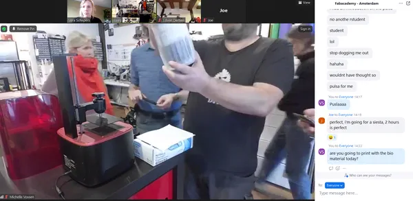
This I was very curious about, at Waag Laura shows us the bioprints she made using her own material consisting of cellulose, maizena and shredded egg cartons. It’s printed as a past and to dry the material faster she puts it in the oven at 50 degrees. As a tip she says if you need to solidify something maizena always does the job. Also make sure the paper is grinded very fine for the extrusion otherwise the nozzle can clog. I’ve printed clay before and here I had the same problem that if there is a slightly bigger peace in the clay the nozzle can get clogged especially small diameter nozzles. The machine uses a motor to press the syringe. She uses pronterface to simulate and view her Gcode.
Group assignment
We discuss our group assignment and want to focus on printing with different kind of materials and tweak the settings to get the best results. Our goal is to print the Bengine in various materials with as little changes to the default profile as possible. Stock settings first, maybe adapt a little bit if required. At Waag Leo Edwin, Joany, Henk and Michelle started printing a bengine on the ultimaker 2S+, Prusa i3MK3s and Elegoo Mars with resin. Joe and I tried to follow the process online. You can find their bengines when you click on the links.
We decide to use the following presets:
- Use slicer of manufacturer of the 3D printer
- 0.4mm stock nozzle
- 0.15mm layer height
- 2 wall lines, 5 top & bottom lines (meaning 0.8mm wall thickness, 0.75mm top-bottom thickness)
- Infill pattern grid
- Infill density 20%
- Print speed 0.60 mm/sec
- no support
- First try without brim (only when needed add a brim).
3 materials test for the Bengine
Bonus Bengine: Ultimaker S2Extended, PLA, I accidental slices the wrong Bengine Oeps! however this one does work right away! The Ultimaker2 Extended plus seem to have some trouble printing the overhang.
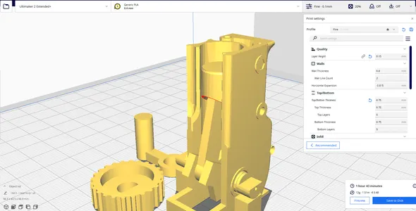
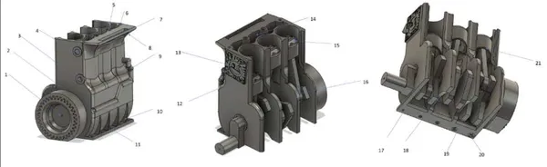
The right bengine is a bit of a challenging test an it takes about 2 hours to print. Apart from the moving test it has a lot of other features that I can look at. I printed three materials adjusting as less as possible from the settings above.
Bengine tests:
- 0.7mm channel through crankshaft
- 1.2mm channel to cooling chamber
- 1mm hole in vertical plane
- 0.3mm Embossed hex
- 1mm hole in horizontal plane
- 0.5mm hole in horizontal plane
- 20mm Bridging
- Freestanding overhang
- Freestanding pipe
- Thin ribs
- 0.5mm holes close to build surface
- 0.86mm embossment at 5deg
- Detailed embossment
- Cooling chamber/internal surfaces15.Valve pockets / Vertical resolution16.Radius
- Warping test
- Arching overhang (10mm Radius)19.Bed adhesion
- Elephant footing test (base hole 0.5mm, chamfering: 0.8mm, 0.5mm, 0.3mm, 0.1mm, 0mm
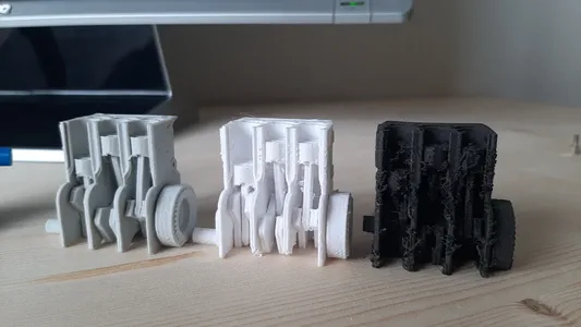
Ultimaker S5, PLA, grey At my job I start the right Bengine with PLA from Formfutura. And slice file using the discussed presets. The print looks pretty good, but when I want to move it I can’t wiggle it enough to break the resistance. I’m not so sure were the print is stuck but it’s not moving. I think might over-extrude slightly because I can see the material oozing out a bit at some parts. Like on test 13 and the hole tests clog up a big. Maybe that is why it’s not moving. Also can be the print speed I like print detailed part like this slower so it can print more precisely. I will try this with my personal assignment. Didn’t change the settings at all and put material temp on 210 C and buildplate temp on 60 C.
Ultimaker S5, PET-G, white The first try let loose from the buildplate, the Ultimaker s5 levels the build plate automatically making a height map. Sometimes there can be a peace of plastic stuck to the bed and level it wrong. I clean the buildplate and start the print again. I can’t move the bengine because it’s stuck again I wasn’t really expecting it to move. It has a bit of stringing and I can see fine overhanging details are printed less. Looks like it’s printed a bit to hot especially with pin like features like test number 19 the free standing pipe and the leg of the Arching overhang. The material seems to not get enough time to cool down. Deforming and Stringing appears. Didn’t change the settings at all and put material temp on 240 C and buildplate temp on 60 C.
Ultimaker S5, LW PLA, black this print has severe retraction problems. Where the Pet was stringing the LW PLA is leaving extra little peaces of material at all the start and endpoint of the layers. Pins are very fragile and I broke the handle when I tried to turn it. The bridging (number 7) on the top is bended way more then the PET and PLA, however the detailed engine pipe on the back came out very nice! Changed the settings a lot because of the material tests we did you can read about it and the settings below.
Bambulab carbon x1s, PLA, The only working Bengine I printed of my test prints on the Bamulab using Bambu Studio. I used the presets that we disgust but I did print at a speed of 120 mm/s causing the print to finish in half the time of the Ultimaker. Super impressive to se the high level of detail it can achieve at these speeds and that’s the input shaping showing it’s work. I learned that the machine and material have a big influents of the accuracy of your prints, the ability of overhangs, pins, holes everything. But this is especially when you push the limits with your design such as with the Bengine. I personally like to play my cards safe when designing something for 3D so I have a bigger success rate. As it takes a lot of test prints and runs to figure out how to get the perfect printersettings and when you switch to a different machine you can start over again!
Test a new material Light Weight PLA
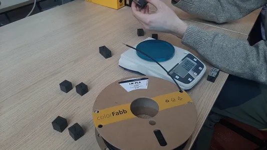
 How lucky, at friday I walk into the Fablab Arnhem and there is a student working on printing a (for me) new material called Light Weight PLA from Colorfabb. He want’s to print this material for replacing the racing car (one of the student car teams of the HAN University I work) PLA components to save weight! I have printed Fiber infused filament, PET, PC, Flex and other stuff before but never this. He already started with my college Niels yesterday by printing this calibration cube in PLA material as a weight comparison. And started printing the first cube using the following recommendations on their website on how to print the material. The material expands nearly 3 timer it’s volume when triggered by temperature. the material flow can be decrease up to 65 percent so you can make lightweight prints. Assuming nozzle size and layerheight are fixed, our main input variables are Temperature, speed and flow to determine the amount of expansion. In this case we fixes the nozzle size to 0.4 mm and the layerheight to 0.2 mm. I jump in to the process because it fits perfectly in our Waag group assignment question “what to tweak when printing with a new material” and I can do this during work time!
We started:
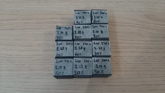
- printing 3 pares of 4 cubes at a set speed of 50 mm /sec varying in temperatures of 210, 220 and 240°C
- print cubes with decreasing steps of flow (50, 60, 70 and 80 percent) using temperature found above
- measure the cubes and compare the weight. PLA cube size 20.02 PLA weight 4.14 g
- Test the best result: flow 60 temperature 240. This cube is not under-extruding or over-extruding, the measurements are closest to the PLA cube. And it;s the most lightweight. Almost half the weight of the PLA cube. We use this result to test the ultimate test the bengine. Curious that it will do since we only tested the expansion and weight but no bridging, small details, overhangs etc. yet.
 Extra info on the setting, these settings stayed the same.
 - Used cura slicer
- 0.4mm nozzle
- 0.2mm layer height
- 2 wall lines, 4 top & bottom lines (meaning 0.8mm wall thickness, 0.80mm top-bottom thickness)
- Infill pattern triangles
- Infill density 15%
- buildplate temperature 60
- Print speed 0.50 mm/sec
- no support
- no brim
- Fann speed 0
Weighting the filament and comparing the foamy expansion with a normal PLA print is something I learned from this material testing. It’s a cleaver way to start from something that’s well tested (our PLA) and compare it with the new material. I will keep this in mind. I would always recommend
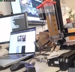
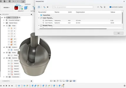
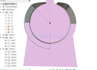
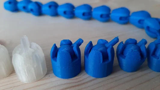
Ball Joint - in place printing
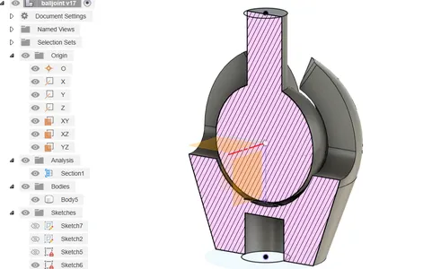
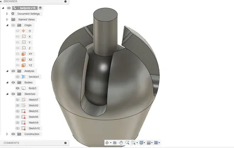
For the personal project I start designing the ball- joint I have in mind in Fusion using parameters for the tolerance and the size of the ball joint. I will make this joint to complete the design and 3D print an object (small, few cm3, limited by printer time) that could not be easily made subtractively exercise. My joint turned out about 25 mm in hight. For the clarence on the Ultimaker S5 0.15 on average 0.15 mm on a side gives a tight fit and -0.3 mm a loose fit. For in place printing I start designing with a tolerance of 0.2 mm and after my test print I kept changing and testing below you can find my findings.
Steps of the design process
- I start a sketch on the YZ plane and draw a half circle with the origin in the middle.
- Revolve this into a ball using the Z-axis
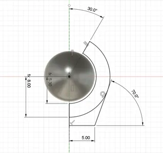
- Draw the outer shape of the joint creating a new sketch on the YZ plane again using p to project the ball and using the parameter tolerance to start sketching from this point a new arc. This wil create the outer shell. I give it a wall thickness of 3 mm and make sure I design within the angled limitations of 45 degrees so I don’t need support.
- Revolve This shape into the shell around the ball joint.
- create a new face on for using construct -> offset plane
- Sketch a cross using the rectangle tool, the width I set to 4, this will be the width of the cross sloths.
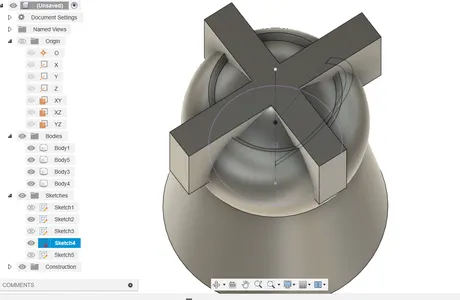
- Extruded it downwards making sure to click create new body instead off join
- Use the combine feature use the extruded cross as the tool body and the shell as a target body.
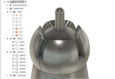
- Create an offset plane for the pin and use the extrude function and make sure I select until next object in this case until the ball and put the bodies to join
Printing and adjusting the design
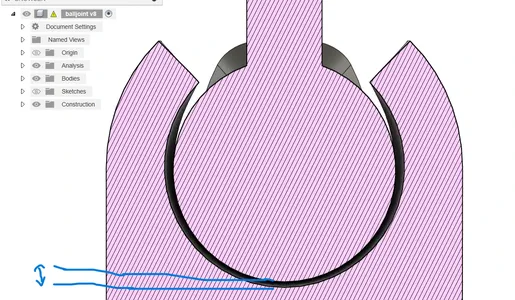 Did some test prints with the following tolerances between the two blue stripes:
- 0.10 mm
- 0.15 mm
- 0.20 mm
Unfortunately all the test (grey) have a ball that is stuck and is not getting loose even when I try really hard. I even tried a second printer (transparant PLA) but still stuck. I think the inner shape might move and merge with the outershape, and I think the printer is slightly over extruding. So I decide to go back to Fusion. I had to go home now and switch back to the Ultimaker2 Extended plus instead of the Ultimaker S5 from work.
I add a plane tangent to the bottom of the ball and sketch a small rectangle of 0.2 mm width and 0.15 mm height that will print a small bridge were the first layer on the ball can rest on.
In the slicer I can have a closer look and it just right. On layer of free space then one small bridging line and then the ball’s first layer.
I stop the printer at the critical moment and i can easily remove the small inner droplet, I have confidence that it will work now!
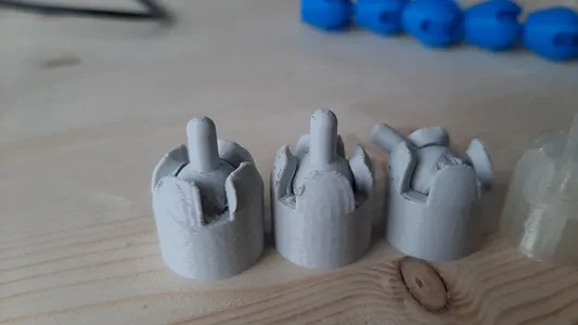
I first try and print the shape with 90 percent flow because it looks like the printer is slightly over extruding. The first working print! The joint is nicely printed and loose! But I see there is just a little tiny bit of under extrusion.
I print the part again with 100 percent flow it seams to print fine now! Since this is a different machine it has different settings again:-) The only thing i’m not very happy about is the pin on top it’s a bit deformed.
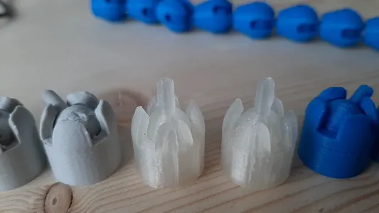
I print another one putting the Z-seam to random to see if it helps the deforming on the top, the Ultimaker S5 didn’t have this problem. The pin turns out better but the outershape looks less nice. Print another one there I break the pin.
I decide to print another with the z seam back to sharpest corner and and and slow down the speed a bit to give it more time creating a round shape.
As the last step I extrude a hole from the bottom to so you can put the ball joints in a row and play with it a bit. I also give round fillets so the pin falls nicely into place.
I slice two of them and they fit. And then I print a few more. My tolerance of 0.15 on every size so 0.30 for a hole was a tiny bit to wide to get a snap joint, with some pins deformed a little bit a put a droplet of glue so they wont come loose during playing with them and I decide to finish this assignment here.
Design and printing gears
Kinetic art work
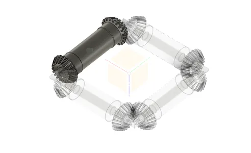
I want to do something with kinetic art and I found inspiration from Anthony Howe. He makes these mesmerizing wind sculptures that are often made by circles that turn inwards. I might want to use this for my final project night light idea but i’m not sure yet. I think if I would add acrylic shapes to see what kind of light bending will happen when it’s turning I think it can be a really cool thing. But I see is as a spiral development. You can find more information about this on my process page of the final project. I found this youtube channel called Geo3Dprint and he does a lot with printing moving structures inspired by origami and he has made Anthony Howe inspired kinetic works he 3D prints. I found this video and I want to try to design and print something similar to this it’s using beveled gears to make the movement. It’s not showing how he design it but he does have animations of the design finished in Freecad to help me figure it out. Since I never design and print my own gears before I look op a few tutorials about making gears in Fusion360.
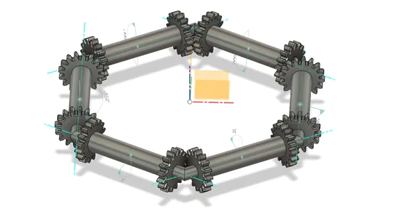
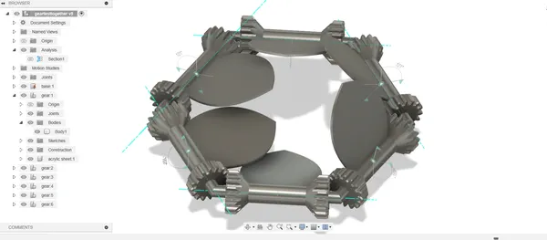
My design process for this was super messy. I changed the design a lot on the way trying to figure things out. Below you can see some of the stages my design has been in. I will try to describe how I build the actual design on the end.
Design process
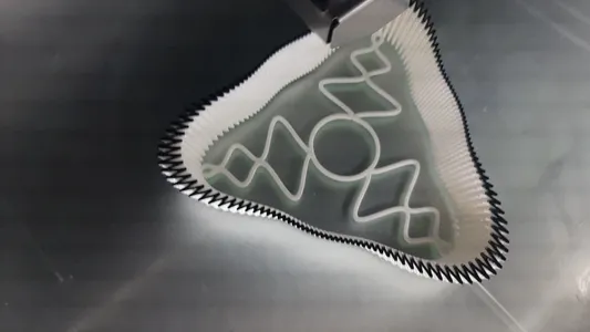
I start with a new sketch and draw the polygon shape.
I make another sketch on a 90 degrees angle from the first one of a circle and use the revolve feature to make the base where the gears will turn from.
I open a new file to test the spurgear plug in, I watch a few tutorials and test it out myself and I create a gear with 16 teeth.
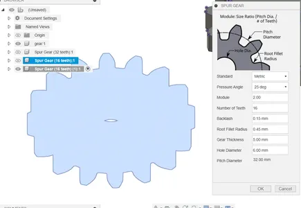
I follow the bevel gears tutorial and copy the sketch of the generated gear I created and past this inside a new sketch.
I use the offset tool to create the bevel and created a new sketch in Fusion to calculate the offset. I used the 20 degrees because the polygon I create at the start has 6 sides / 2 would be 30. As I’m typing this right now I have no clue anymore why I made it 20? It should have been 30… But yeah I used 20 and used an offset of 0.5 mm so and measures the length of the other leg of the triangle using dimension and give the offset plate an offset of 1.374. I used a bit of a trial error approach for this. I think these is probably much better ways to design this but I could’t find it.

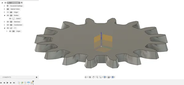
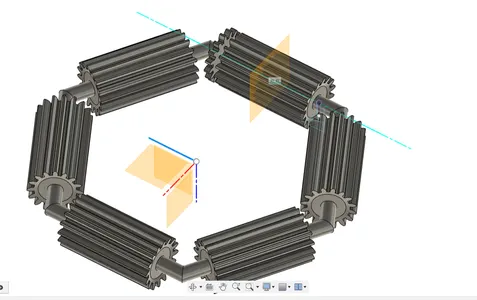
After my test gear I do the same process and start creating a new component in the main file and use the mirror tool to mirror my offset gear design to both sides.
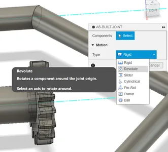
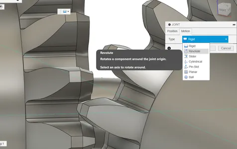
After doing a revolve cut extrude and a hole cutout of the diameter of the polygon shaped thread, I copied the gear component 6 times and placed it in the main component. I make new axis inside the components to use as a reference for the joins and then I use the assemble-> joint -> motion -> revolve to make sure my gears can move.
To calculate the amount of degrees the 3 gear needs to be turned in my assembly for al the 6 gears to align I used the following formula: 360/16 (amount of teeth) = 22,5/2 (because we need the middle of the teeth to align)= 11,25 degrees turn.
For the length of the gears I adjusted it by eyeballing it and keep looking closely to my assembly.
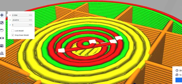
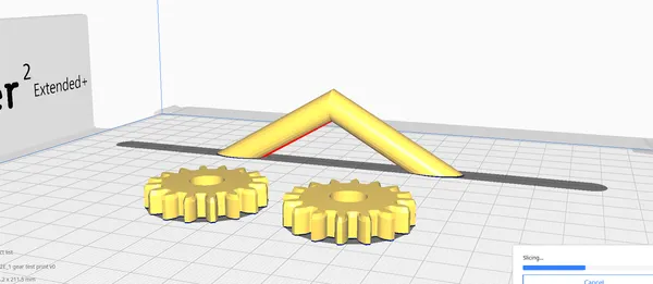
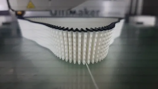
I make my fist test print to test is the gears are working. In Cura I only slice the parts that are absolutely necessary for my test and the print came out really nicely!
Slicing settings:
- 0.4mm nozzle
- 0.2mm layer height
- 2 wall lines, 4 top & bottom lines (meaning 0.8mm wall thickness, 0.80mm top-bottom thickness)
- Infill pattern lightning
- Infill density 15%
- buildplate temperature 60
- Print speed 0.40 mm/sec
- no support
- no brim
- I adjust the holes in the gear to make a ball bearing (diameter of 22 mm by 7 and an inner diameter of 8 mm) fit inside the gears so it will turn smoothly. I only have to do this for the 1 gear and all the copies of this shape will adjust automatically.
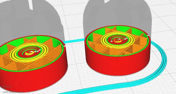
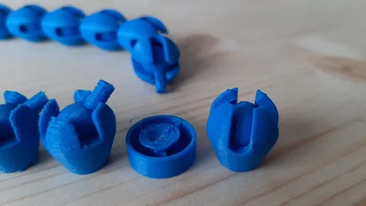
- I made a test print of the 6 gears and the hexagon shape and try to put is together.
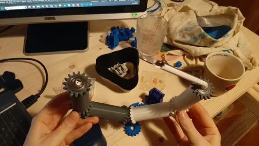
Unfortunately one side broke because the hole of the gears was to tiny to make the angle when assembling and I forced it. Should have checked this in my design, but I can still test the system and here gears work! I don’t like that it’s so big and robust I wan’t to make a second version more delicate and probably need to find a better way to designs beaveled gears..
Fullcontrol test
The whole kinetic gear project took more time then anticipated so I only have little time left to try something with g-code editing in Fullcontrol.
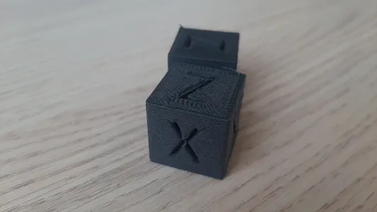
I start by following the tutorials on their site where they work in a excel sheet and show how to import lines object, how to put in the coordinates, how to use a multiplication and how to add a printer changing the Start and End g-code. I then went to their website that has preset models and altered a design in the web browser just to get started. I select the right printer i have a ultimaker2+ extended but I can only select the ultimaker 2+ and clicked on download g -code. A pop up opens saying the file is to big and I have to aces the model via google colab for the printing, you can download the file yourself from the same link. I follow this tutorial for a quick start on this google colab page and download my g-code file here. I looked inside the gcode file thinking I need to change the max Z-height because I print with an extended ultimaker 2+ version but I can’t find this in the gcode. I’m assuming it should be fine then and start the print. It start printing and it looks really good. It’s nice to see the printer making a totally different path then I’m used to. Before I know it the evening was gone and I stopped the fullcontroll try out there, I didn’t opened the code in python or designed my own shape. It’s something I want to do in the future.
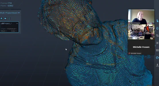
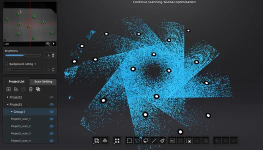
3D scanning
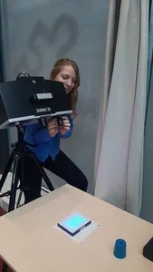
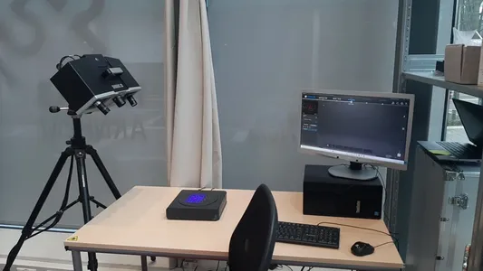 At the Fablab Arnhem we have the Shining Optimscan 5M Plus. This scanner on a tripod is used for extremely accurate scanning of small to medium-sized objects. The scanner uses light projections and cannot detect colors. The scan has an accuracy of 0.005 mm and a 0.004 mm resolution. The max. scan range is 35 x 35 x 35 cm. The scanner uses markers to align different scans and right now is doesn’t recognize it’s markers anymore. I want to go through the whole calibration process again to see if I can fix this problem for our lab and also make a scan for this weeks assignment. Because the scanner can scan such small details I will try to scan a fersnel lens and see if I can get the details and lines of this flat lens. I can’t scan transparent things and I don’t want to coat the lens either because the details are so fine i don’t want to fill them with spray coating. So I decide to make an imprint on the lens using silicon and then try to scan the silicon imprint with the scanner.
Steps
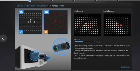
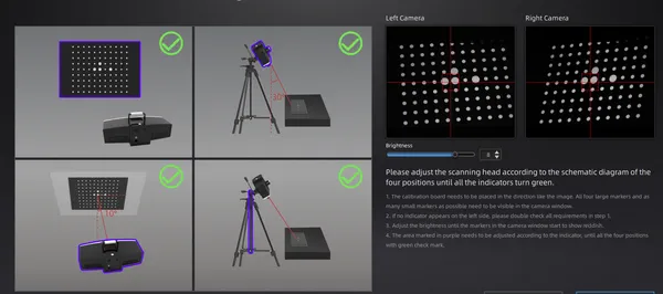
Doing the calibration process again by following the steps of the shining software. It’s a lot of steps but if you read well and have patience it’s not that hard to follow. I will calibrate the focus, aperture and align the laser again hoping the markers problems are fixed afterwards. This process takes quit some time.
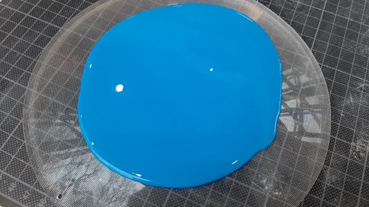
I pour 40 grams of silicon (1:1) on to the lens and wait for it to harden.
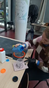
I past some small markers matching with the lens size. This machine has 3 different lenses and every lens has it’s own size of markers (don’t mess them up).
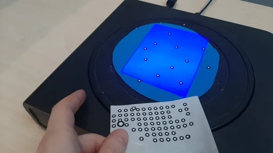
I try scanning the imprint. Good new the markers are recognized again and we are getting some data! Bad news when using the turnable to scan around the object. I can only get one side of the silicon to scan properly. The other side is scanning the markers but no data. The side that is scanned does have perfect little detailed lines so i’m happy about that. I try to scan another object and this goes well so I think it’s the reflecting of the silicon together with the flatness that makes it hard to scan this.
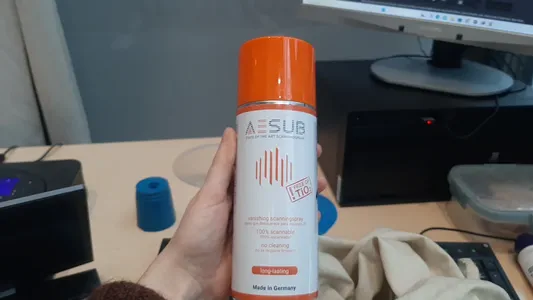
 5. I’m going to spray a bit of scanning spray on the object to see if it would help. It should get rid of the shininess.
 6. Even though I have data all around the object now it’s not as good as a scan than the previous one oddly.
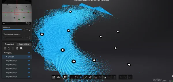
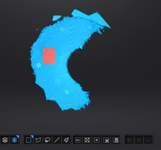
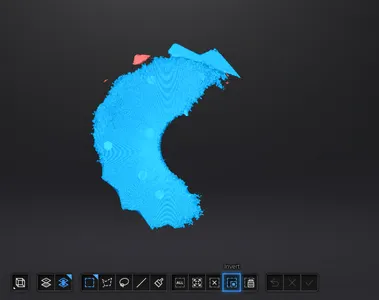
Being curious is the flatt surface is the thing that it is struggling with I fold the peace of silicon and scan it again. I’m not using the turntable now but i’m manually turning the object on the table making small steps. It looks really nice and I’m happy with the process.
For cleaning up the scan i like this button called invert. You first select the main components and click on selecting connected domain, I then use the invert button to invert the selection and now I can remove all the flowing parts at once.
Here you can have a look at my flat and folded 3D scan of the imprint of the lens. I didn’t really know what to scan for the assignment and I thought to maybe reshape the fresnel lens and use it to deform the light for my night light final project but I don’t like the plan anymore the lines are way to tiny to make something new out of the scan and I don’t think it will deform the light like I imagined. So I’m not going to do anything with it but it was nice to practice with the scanner again and to find out new stuff about scanning silicon.
Files
Reflection
I’ve already in the text reflected on the assignment I did this week. Overall it was not my best week, I had to catch up a bit from beeing a bit sick and I missed working together with people. This week was more on my own a lot of work I did at home. I found a challenge in drawing the gears and I still have much to learn about this. I might have lost myself in the process making it a messy designfile, messy documentation and leaving little time to try out fullcontrol. But I was also happy to have something that turns at the end. Not a lot of firsts this week, the upcomming week will be a lot different since I have little knowledge that subject!
Feedback
- test variable layerheight to print the pins of my inplace printing easier