Electronics Production
intro
Goal of this week is again a group assignment and individual work, focussing on production of electronics. During the bootcamp we already did a small bit of (SMD) soldering using a mini (USB-C powered TS80) soldering iron. This time I hope to industrialise the process :) - paste stencils, here we come!
Group assignment
- Characterize the design rules for your in-house PCB production process: document feeds, speeds, plunge rate, depth of cut (traces and outline) and tooling.
- Document the workflow for sending a PCB to a board house
- Document your work to the group work page and reflect on your individual page what you learned
Individual assignment
- Make and test a microcontroller development board. The board to make will be the quentorres board containing a seeedstudio XIAO (RP2040)
group assignment
At de Waag there are currently two milling machines. The trusty Roland Modela machine and a brand-new (40x cheaper) 3018 (genmitsu) machine. During this group assignment I teamed up with Vera Schepers. We use the test files and 3 different milling bits:
- a 0.4 mm end mill
- a 0.25 mm 15 deg. tapered ball-nose
- a 0.1 mm 30 deg V-bit
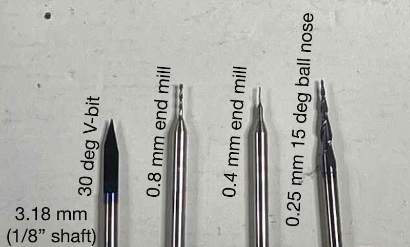
the milling bits used for the group assignment
The software used for producing G-code (for controlling the machines) is mods. For the Modela mods is running on its control machine. For the 3018 mods is only used to generate G-code (and UGS is used on different laptops to control the machine)
modela
The Roland Modela MDX-20 is a robust machine found in many labs. Even second hand they are very valuable. The following notes were taken during the demonstration. In the next section as group assignment a characterisation using a number of different bit types is done.
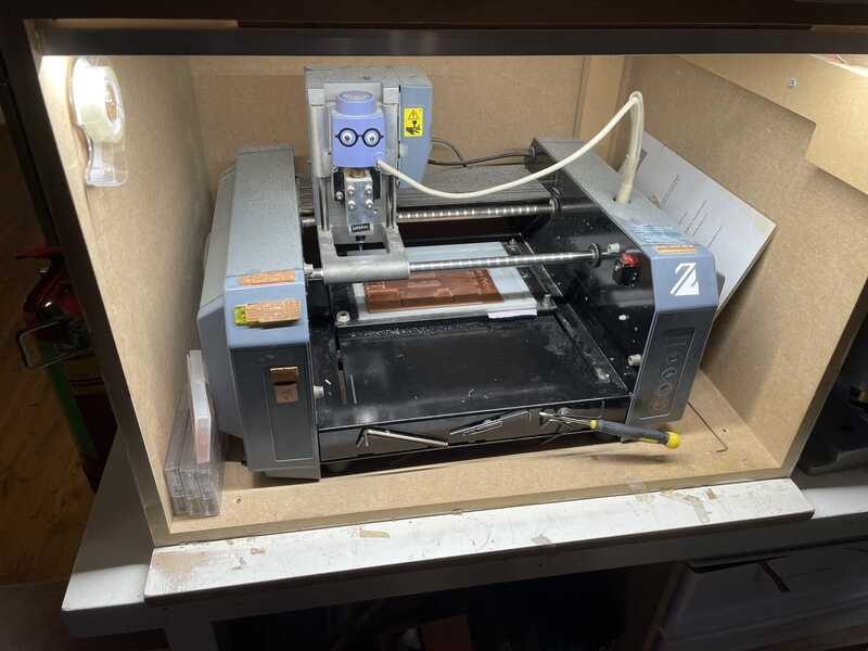
Roland Modela MDX-20
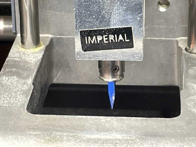
The collet with 1/8'' bit, tighten with (one) grub screw
Set up instructions:
- In case of problems: disconnect USB, reset by up+down together -> stop blinking, memory clear + refresh page (mods) -> redo
- view button: switch between setup and operation mode
- stroopwafel punishment for not putting back double-sided 3M tape roller in the box at the side
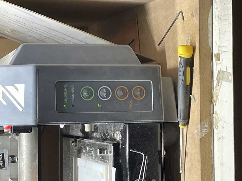
control buttons: view is a good 'emergency' stop

preparation: cut path in mods
In the lab Henk and Erwin show the Modela in action, giving the following advice and instructions:
- modela: insert bit higher in collet (use small allen key)
- modela: ress ‘view’ to go in operation mode
- modsL webserial get device, select, connect
- mods: go to home (starting pos), z+1mm
- modela: lower bit on material using the allen key
- mods: select bit, check values, overlap, ratio -> note: tapered bit(!)
- mods: calculate ->
- mods: move head with buttons -> = setting zero!
- pen and paper: record your origin
- mods: png are size accurate -> still, check dpi and resulting size
- modela: view = panic
- mods: copper: 0.035mm so, cut depth: 0.25 should be sufficient
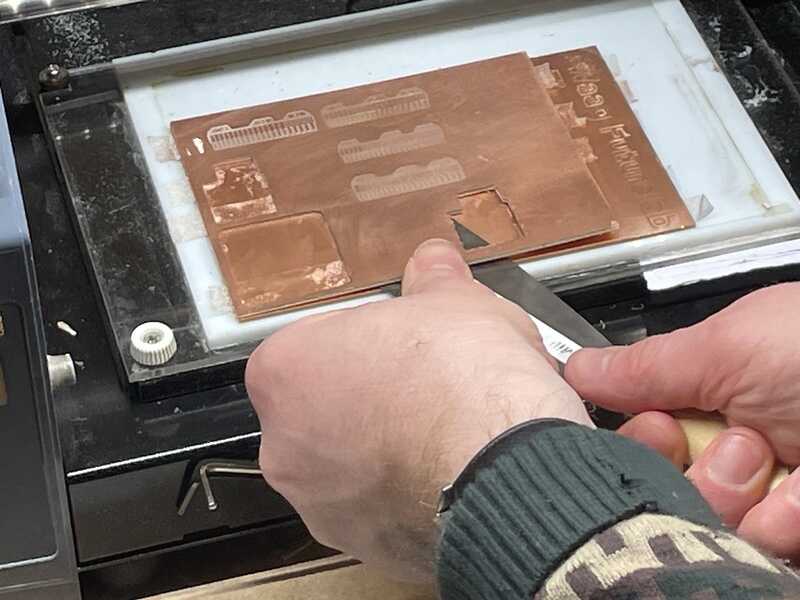
prepare PCB by removing it from the sacrificial layer
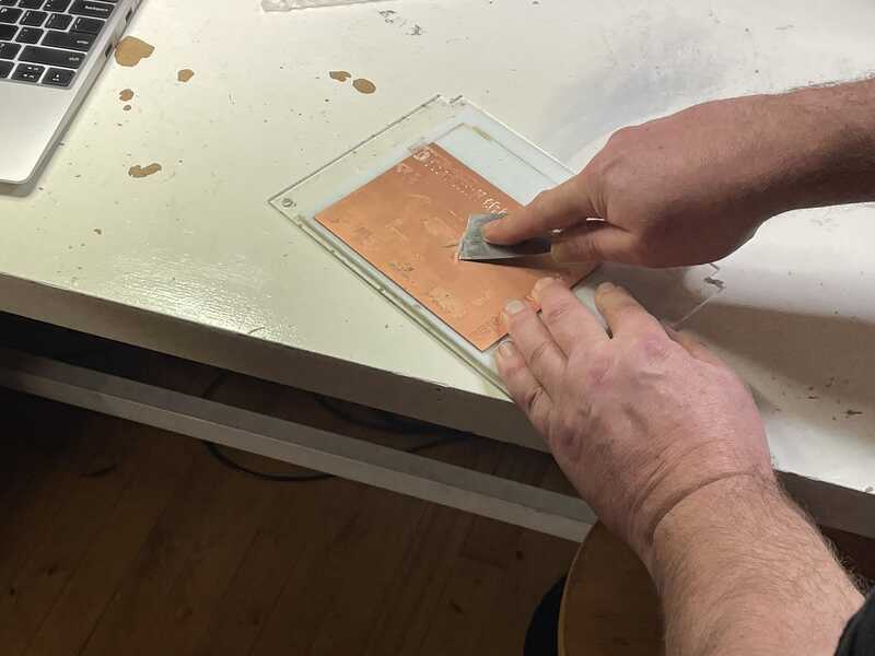
clean the sacrificial layer
It is important that the PCB materials lies completely flat on the buildplate, so carefull cleaning and taping (without overlap) is very important.
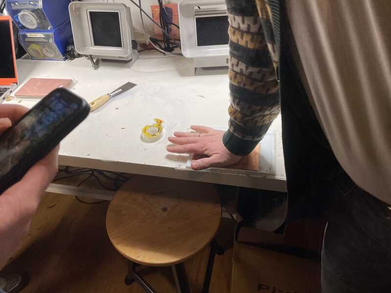
use tape (Joe) to fix PCB on the buildplate
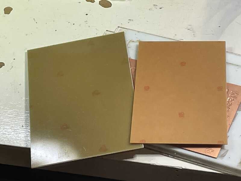
FR4 and FR1. We use FR1 (FR4 emits epoxy and glass-fibre dust)
Typically end-mills deliver very robust and reliable results, at a price of fragility. V-bits are very robust, but have a cut-width depending on its cutting depth. A small ball-nose (such as the 0.25mm one in use) seems to be the ‘best of both worlds’
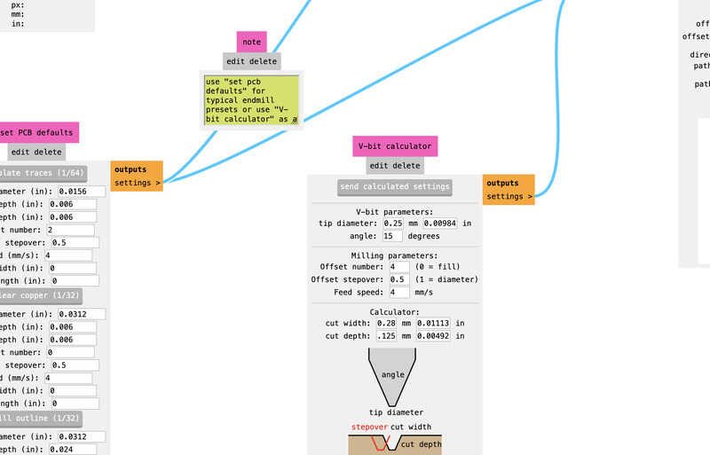
mods settings for 0.25 mm 15 deg ball-nose mill
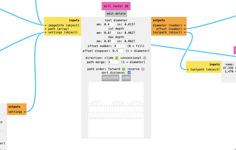
mods settings for 0.4mm end mill (flat)
In conclusion:
- v bit rough finish, ball0nose (tapered) no burs (braam) - no deburring
- tapered = stronger and cheaper than end mill
- end mill: very precise but good for only +/- 10-15 boards
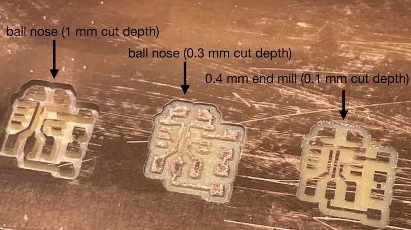
demo PCB's with different settings
modela test
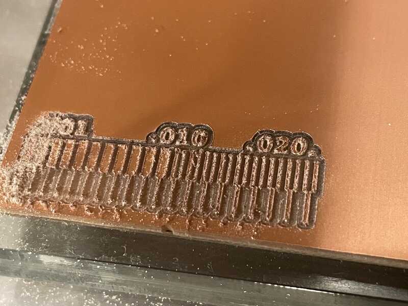
As group assignment we divided the work (Joe, Leo to start on the 3018, Vera, Edwin on the Modela - to be swapped mid-way). Test the line spacing test drawing using three different bits. The file is inserted in mods, (check resulting sizes based on DPI setting).
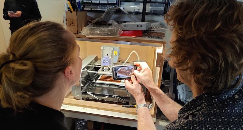
Vera and Edwin checking the Modela's performance, picture by Erwin
- machine: tape pcb and place in machine
- machine: put in miling bit (too high) using grub screw (view mode) -> go to ‘play mode’
- mods: webserial -> connect
- mods: move to x - y position with set origin
- machine: move z-axis with machine buttons until few mm above plate
- machine: release milling bit using grub screw, set on plate. now everything is set
- mods: re-calculate, send to machine
| n | task | bit type | cut depth | max depth | offset | stepover | feedrate |
|---|---|---|---|---|---|---|---|
| 1 | contour milling | 0.4 end mill | 0.07 | 0.07 | 4 | 0.5 | 4 mm/s |
| 2 | contour milling | 15 deg, 0.1 v-bit | 0.2 | na | 6 | 0.2 | 4 mm/s |
| 3 | contour milling | 15 deg, 0.1 v-bit | 0.1 | na | 4 | 0.2 | 4 mm/s |
| 4 | contour milling | 30 deg, 0.1 v-bit | 0.1 | na | 6 | 0.5 | 4 mm/s |
| 5 | contour milling | tap ball 0.25, 15deg | 0.1 | na | 4 | 0.5 | 4 mm/s |
The modela can be seen in action here: video of modela.
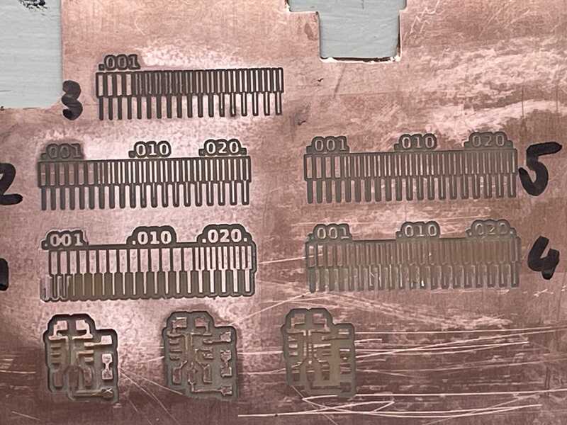
traces of mentioned test settings
conclusions
- henk did a quick manual correction on test 1 by turning the bed screw in the bottom left corner.
- at the end of test 3: don’t reset mods when sending to the modela, stopped in mid-job
- between test 3 and 4: check in: wrong overlap, wrong angle setting, so probably too much cut away
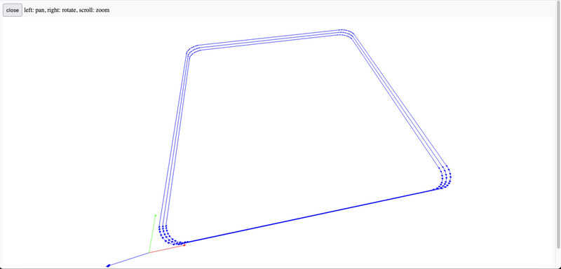
- note: view toolpath in mods shows the actual traces in 3D (!) so you can check cutting depth / passes
- note: end mill is much quicker than v-bit (increased number of passes)
- note: self solder: 1mm clearance is desirable but would take impossibly long with a v-bit
- the ball-nose (5) was the one at 15 deg, not the v-bit
- ball nose (5) does not need deburring, very smooth.
3018
The 3018 is a low-cost machine from Shenzhen based companies such as Genmitsu (many comparable models are available). Differences in bed-size, construction and most importantly the spindle motor make differences in price (and eventually milling quality and consistency)

3018 machine
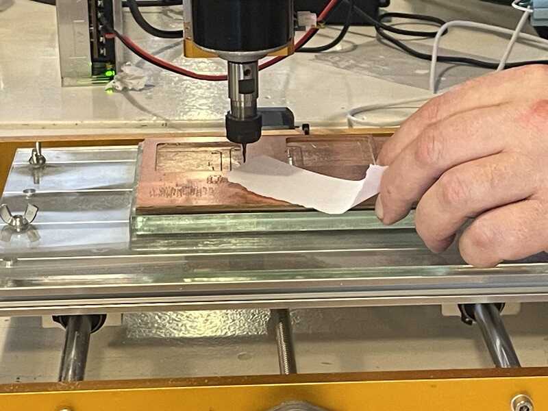
homing the milling bit with a piece of paper
For homing the procedure is a bit different from the Modela because a clamping collet will lift the milling bit a very small fraction upon tightening. Remedy is to lower the bit unto a scrap of paper, testing for friction (much like homing a 3D printer nozzle on the bed). After friction is felt, the paper is removed and paper thickness (0.1 mm) is added to the Z-position. Files are generated in mods, but send to the machine using UGS, a g-code sender. Again, the origin is set in the bottom left corner.
The operation instructions in one consise list:
- UGS: connect (select port, connect )
- UGS: homing from jog control (check step size, feedrate)
- 3018: fit milling bit using wrenches
- UGS: jogging z axis 0.1 mm step until (paper friction). Add one final 0.1 mm to compensate for paper thickness
- UGS: set zero on all axes (X0, Y0, Z0) to set origin
- UGS: load file (on macos: check your directory, see this post)
- check, press play.
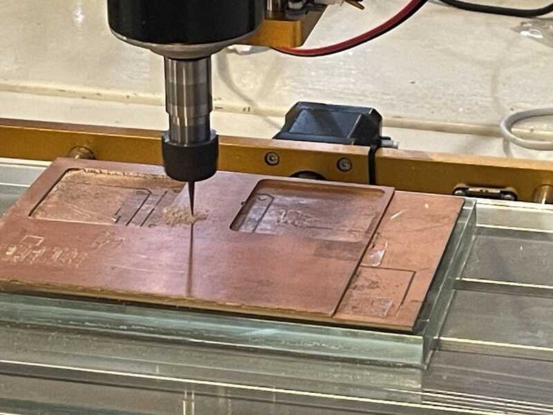
trace routing using ballnose
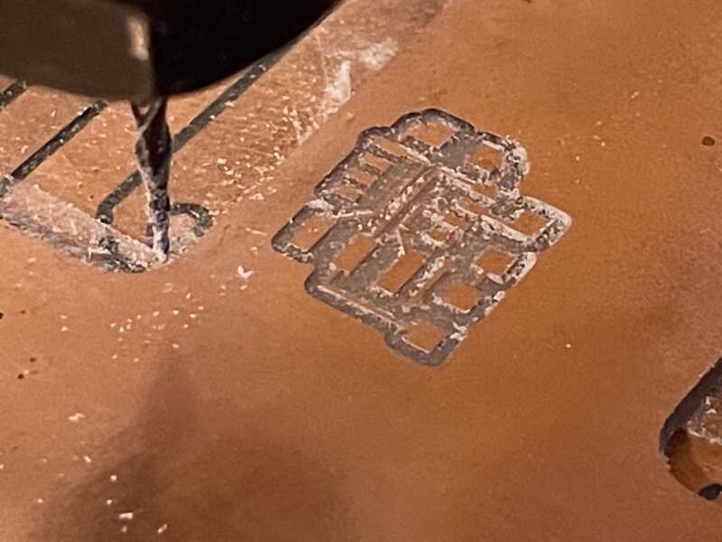
traces milled
Advantage of a ball-nose tapered mill is that, while being still quite accurate for trace milling, it can also be used to cut the outline of the board (don’t try this with an 0.4mm end mill) - In mods the board outline is generated with a separate image file, setting the max depth to 1.6 (board thickness), the cut dept to 0.23, and no step over (1).
outline settings (multiple passes) in mods
cutting board outline (also with ballnose)
The end product is (the same PCB as demonstrated before) quite ok:
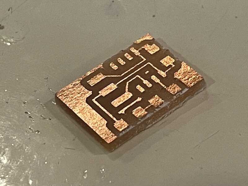
finalised test board
3018 test
Time-wise most of our part of the group assignment was spent on the Modela. We however also tried to cut the line-spacing test bit on the 3018 (to get a feel for the workflow). New in this workflow is the use of UGS to send G-code generated by mods to the machine. The visuals and control panel are very self-explanatory. Also in the individual assignment screen-shots of UGS will be shown.
The ballnose bit (Henk’s favourite) gives ok results resolution wise. On the modela it is absolutely smooth, on the 3018 it shows small traces of burring (so a bit of sanding afterwards would be necessary)
Trace test with 0.25 tapered ballnose
| n | task | bit type | cut depth | max depth | offset | stepover | feedrate |
|---|---|---|---|---|---|---|---|
| 1 | contour milling | 0.25 ball 15dg, set at 0.3 | 0.1 | 0.1 | 4 | 0.5 | 4 mm/s |
| 2 | contour milling | 0.25 ball 15dg, set at 0.3 | 0.1 | 0.1 | 4 | 0.5 | 4 mm/s |
- test (1) first go z compensation not enough. paused and reset job, substracting 0.2 from z position
- test (2) changed z depth a bit (-0.05 further compared with (1)) - no noticable improvement
individual assignment
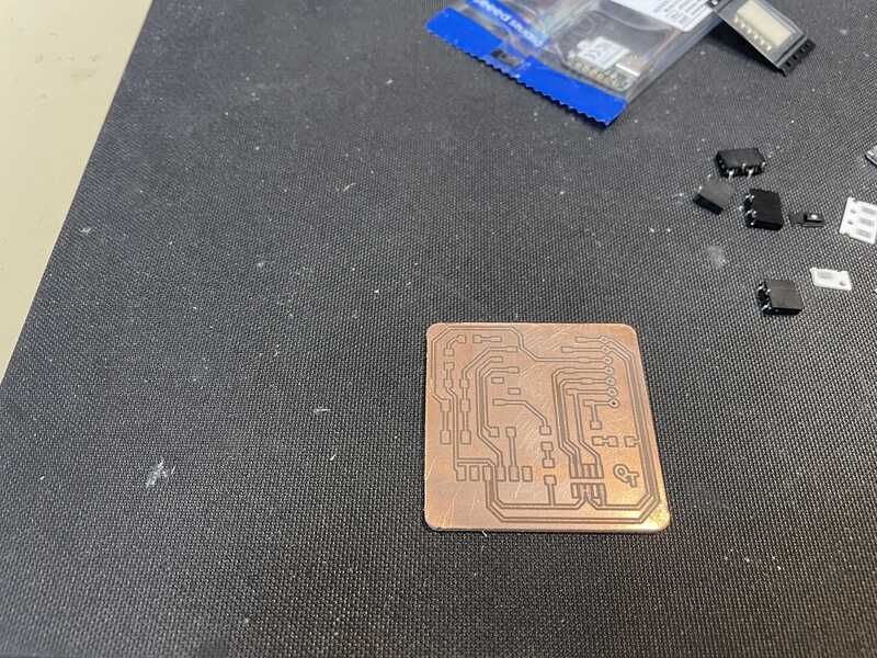
The goals it to produce the board quentorres board and describe the manufacturing steps needed. I used a milling machine at home instead of the lab - but also made a paste stencil to work with re-work tools rather than the conventional soldering iron. If time permits I’ll make another one in the reflow oven.
3020 pro max
At home I have the Genmitsu 3020 pro-max which has to be started up. I re-used the idea/design of the board fixing set-up from the 3018 at Fablab Waag - where a thick acrylic plate is used on the board, including a smaller bit to fix the PCB to. The acrylic glass is very flat, for now I skipped the part of using an end-mill and flattening the surface. I used a small drop of acetone to glue the center riser (same size as prospective 70x100 mm pcb material) in the center.
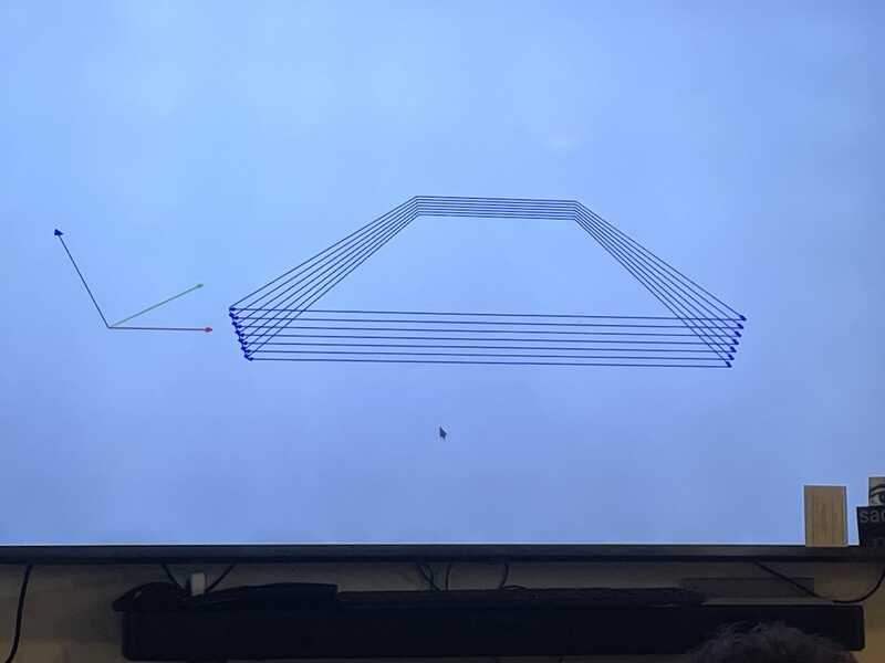
On the 3020 pro Max I decided to try and make the quentorres board. First in mods I set out to do 4 passes - which I had to dial back later to do a 1-pass file because traces were very wide (the wobble I found on the spindle explains this, but I found out about it only later)
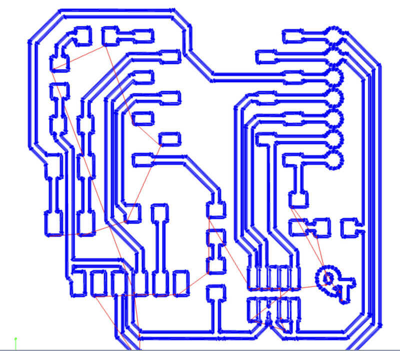
4 pass toolpath in mods
board outline pattern in mods
I found that the track cut by the v-bit were exeptionally wide. By manually adjusting the Z-level (using the knob on top) I could either clear the bit from the board (so no cutting) or immediately cut a 0.5 mm wide track. Using a 10 degrees V-bit instead of a 30-degrees V-bit did not make a difference. Hence the conclusion that there is something wrong with the spindle: an exceptionally large wobble (or very bad balance/allignment/centering). However, since a board -IS- needed and balancing the spindle (or obtaining a good one) will take too much time, I settled for a 1-pass isolation routing, where in mods I set the width of the tool to 0.4 mm (while in practice the V-bit has a width of 0.1 max)
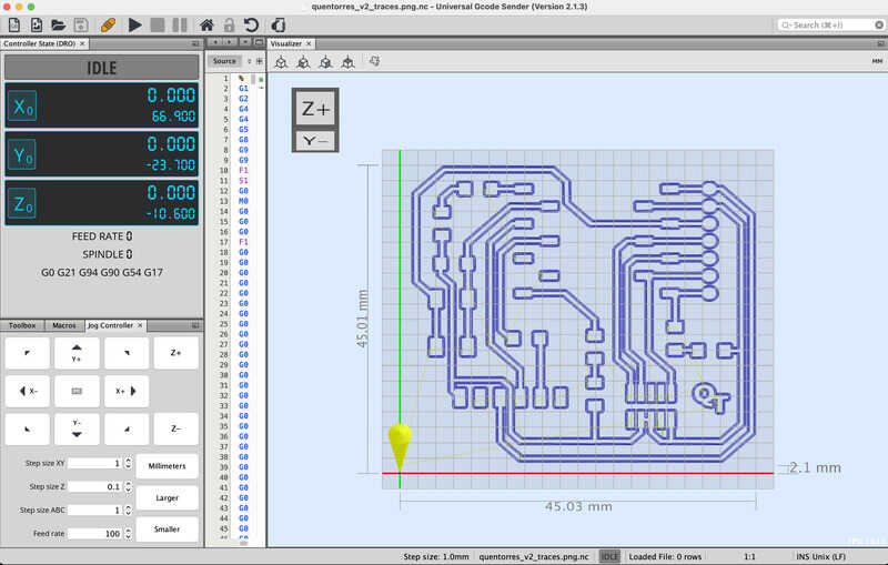
cut path with 4 passes of a V-bit
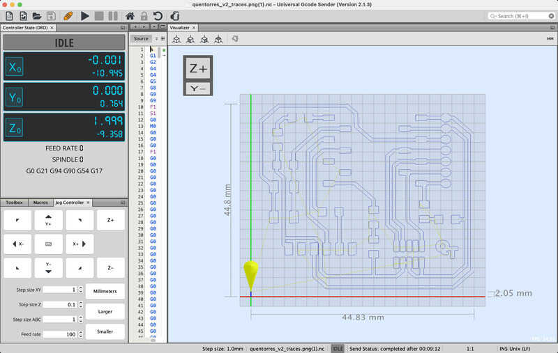
eventual cut path with 1 pass of a V-bit
On the 3020 I build a bed using acrylic glass similar to the one on the 3018: a large plate on the (spoil)board with a rised section, a ‘sacrificial’ PCB taped on that, topped up by the board to be milled
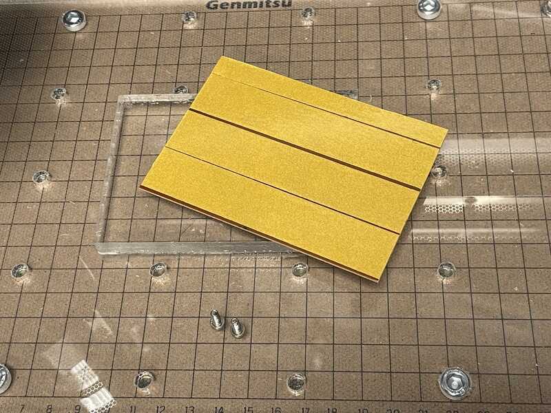
preparing the PCB with double-sided tape
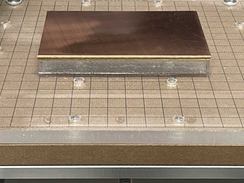
layered bed on the 3020
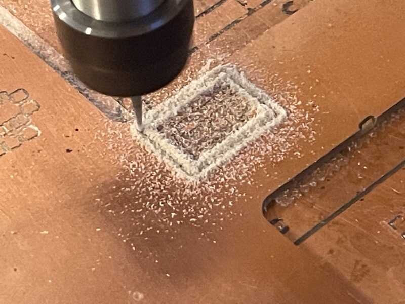
The traces were eventually cut with a smaller (10 degrees) V-bit, in the hope it would cut less wide tracks. The machine did not do well, but the results were OK for a functioning board. See the video of the traces being cut.
genmitsu 3020 cutting traces
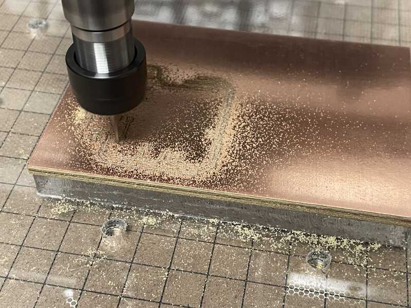
v-bit cutting the track
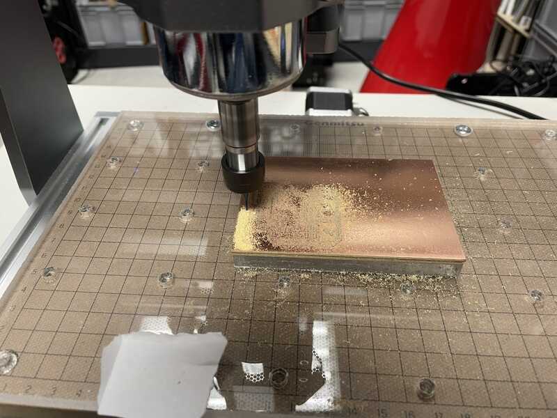
board outline cut with an 1.6 mm end mill
In between I did 2 toolchanges. First I also had to use a 0.8 mm bit to cut the holes, see this video. Finally the board outline was cut using a 1.6 mm end-mill, seen in this video.


paste mask
For the soldering of the board I wanted to give soldering with paste, a hot-air rework station and paste stencil a go. Using the same foil as in week 3 (might be PET) of 0.25mm and a Trotec Speedy 300 laser cutter I experimented with settings to cut out a smooth stencil.
The stencil design came directly out of the Kicad files that came with the board:
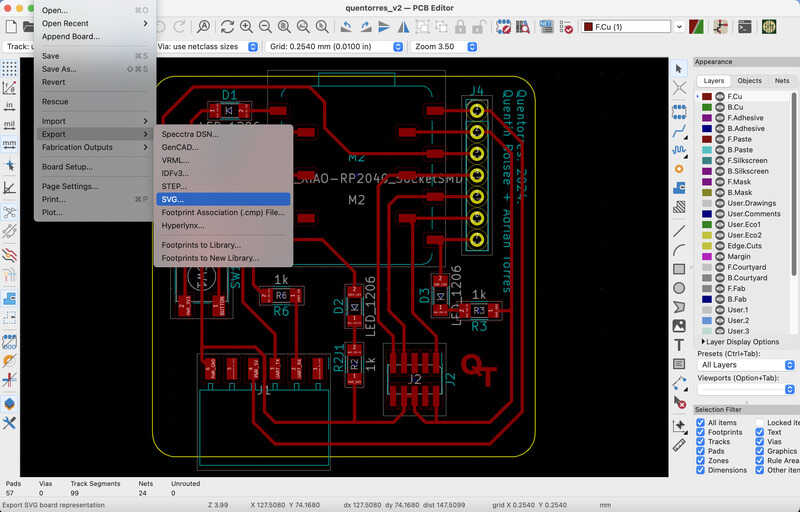
export a layer as SVG
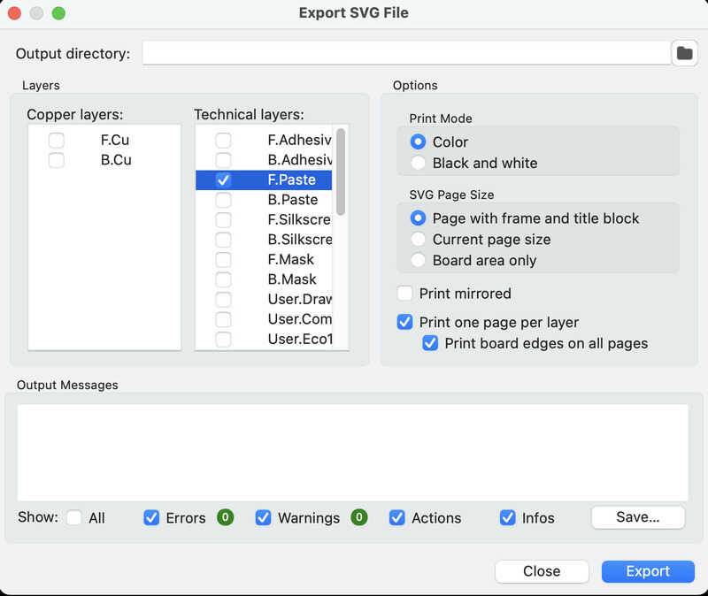
selecting the top paste layer
Next I imported this SVG quicly to Inkscape to set the line thickness, color and remove outer trace / technical drawing artefacts so the file could be imported in Trotec Job Control:
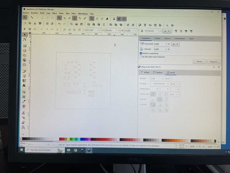
selecting the top paste layer
in Trotec job control I tried the following settings:
- multi-pass, p100, v1.0 (too much)
- single pass, p100, v1.0
- single pass, p100, v2.0
- single pass, p 100, v1.5
- single pass, p 80, v0.8
of which the best so far is single pass, P100, v1.0. See this video for the Trotec in action. The used svg file can be found here
board taped to worktable surface
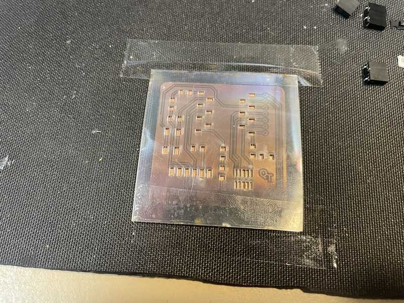
paste mask taped in place
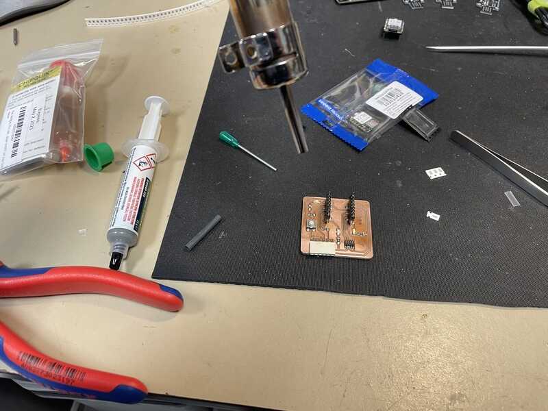
soldering
Next up I dispenced a bit of low-temperature LEAD-FREE soldering paste
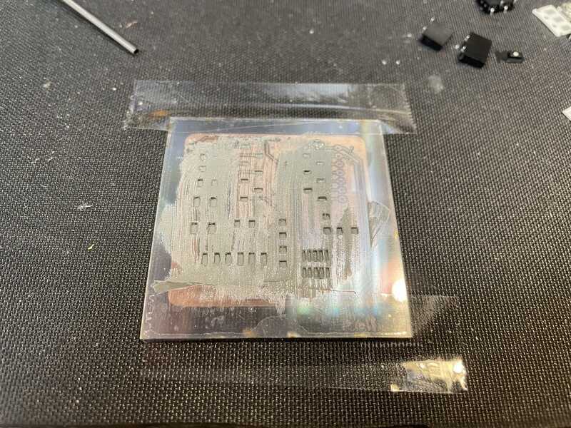
paste applied
mask removed
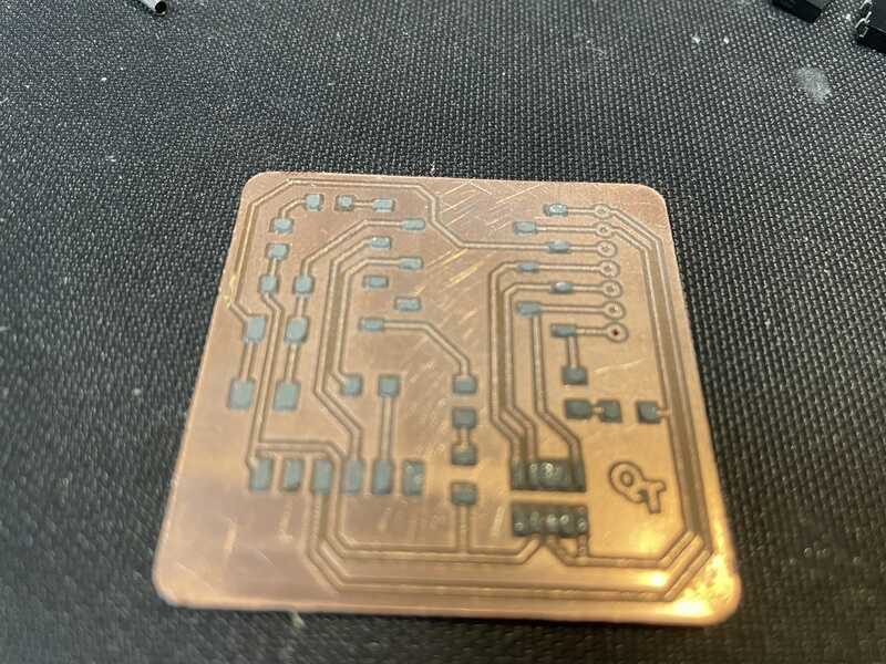
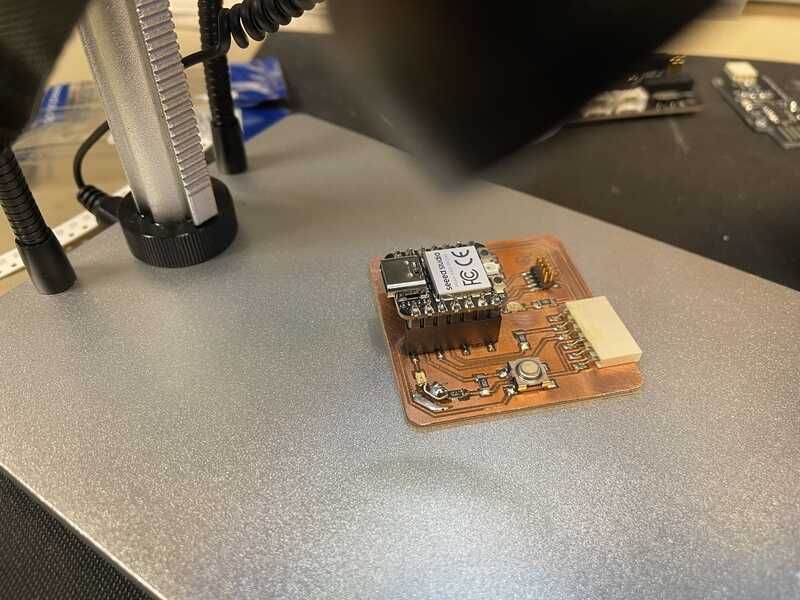
I populated the board, checking LED polarity with multimeter (shown below too) using the kicad board files
parts in place
I used a hot air rework station, which admittedly might have been set a bit too high in the beginning. There is no clear temperature dial, just a 1-7 heater scale. Putting the heater a bit lower than mid-way helped. I gently lowered the iron until the magic flowing bit began. You can see the right side of the board (where I started) suffers a bit from overheating.
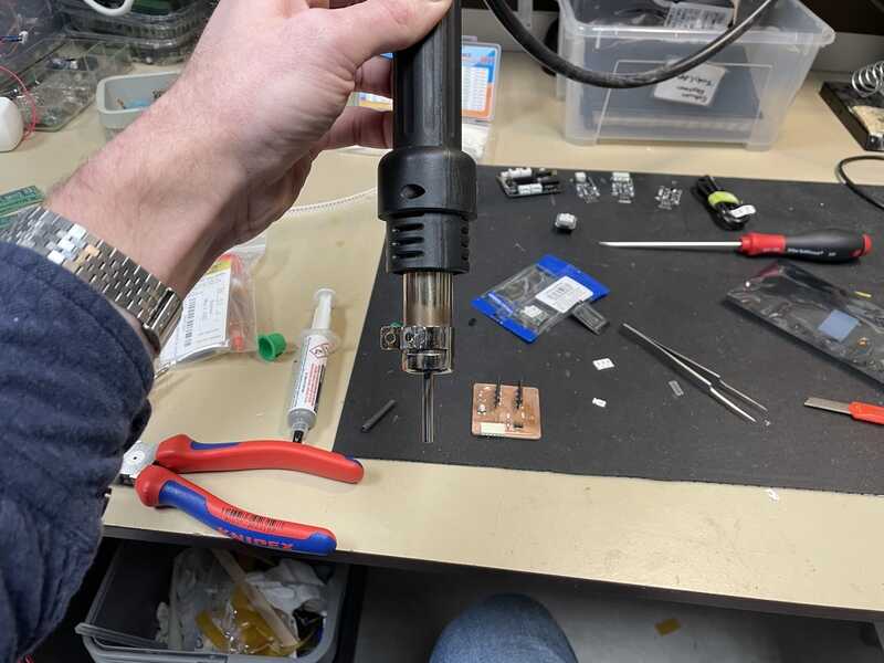
rework station iron
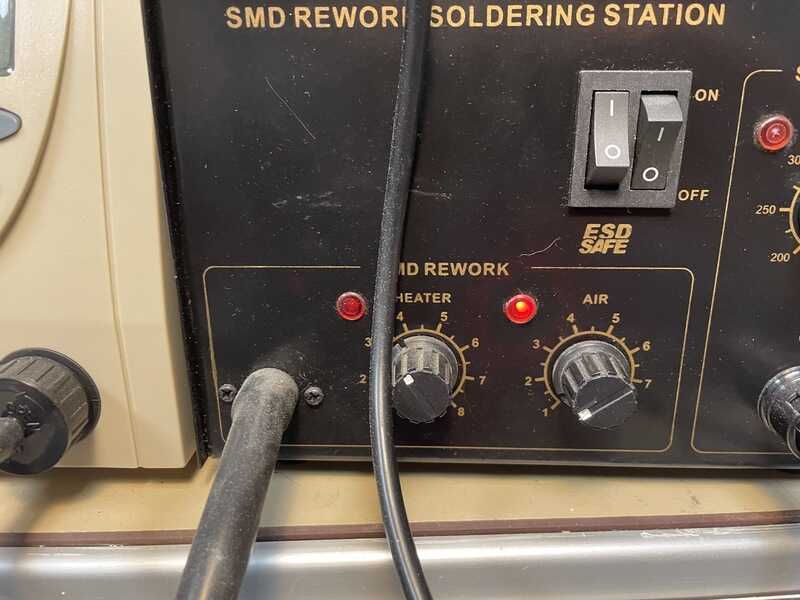
rework station settings
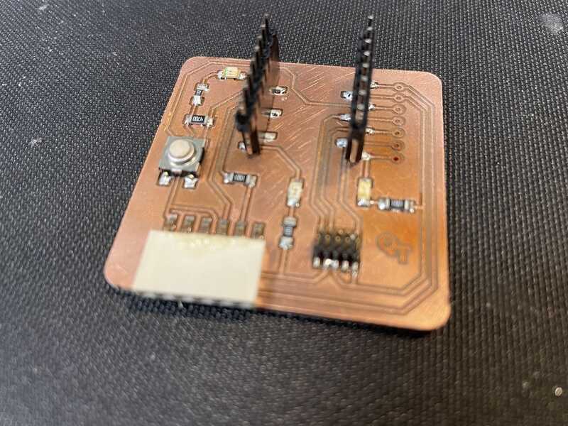
soldered work
a trace came off when re-soldering a resistor that still made a short
soldered work
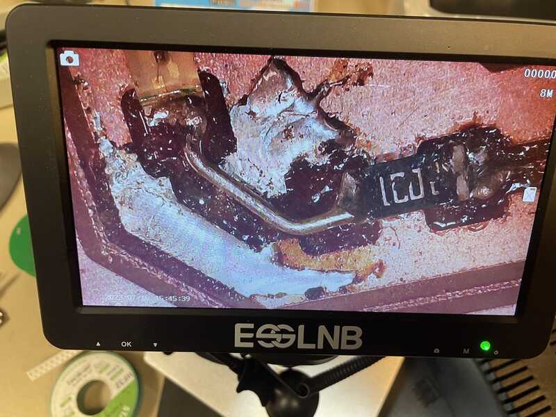
Eventually I looked into the spindle motor. In the following movie you can see that the spindle is not properly balanced or outlined: when I rotate the spindle motor, the inserted bit moves at least 1.5 mm (!) off-center. Also when I took out the spindle and powered it using a lab supply, the x-y plane wobble can be felt. I don’t know whether this is caused by a production error, is something common or should be down to accidental damage. Anyway, for now I ordered a new spindle and will start looking into how to service or balance the existing one. On youtube focus is mostly in balancing the fan rather than motor output. It might also be that I did not use the collet correctly as shown in this post So I’ll do some more digging :)
so it might be this:
Why Oh Why didn't they gave this bit of manual up front....
hello world
Just to check if the XIAO is working I followed the xiao wiki pages for Arduino. entering https://github.com/earlephilhower/arduino-pico/releases/download/global/package_rp2040_index.json in the preferences list for additional boards manager url.
(Compiling for RP2040 in the 2.0.1 Arduino IDE throws a weird warning (abort trap) which does not result in a quick fix. Something to do with Python versions and UTF encoding. Decided not to fix it and revert back to a working 1.8.19 Arduino version.)
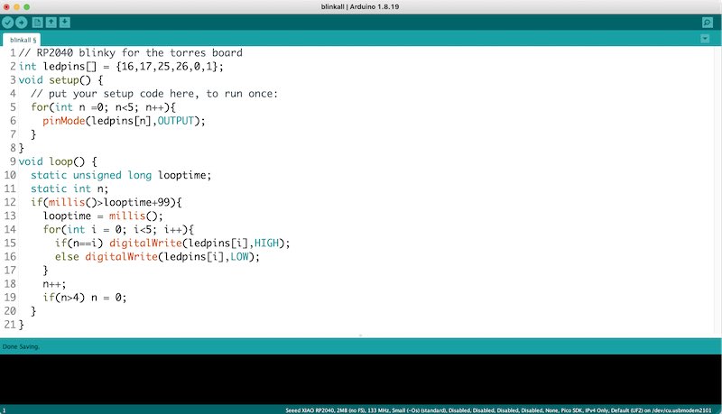
The following program is tried to make the LEDs on board blink:
int ledpins[] = {16,17,25,26,0,1};
void setup() {
  // put your setup code here, to run once:
  for(int n =0; n<6; n++){
    pinMode(ledpins[n],OUTPUT);
  }
}
void loop() {
  static unsigned long looptime;
  static int n;
  if(millis()>looptime+99){
    looptime = millis();
    for(int i = 0; i<6; i++){
      if(n==i) digitalWrite(ledpins[i],HIGH);
      else digitalWrite(ledpins[i],LOW);
    }
    n++;
    if(n>5) n = 0;
  }
}
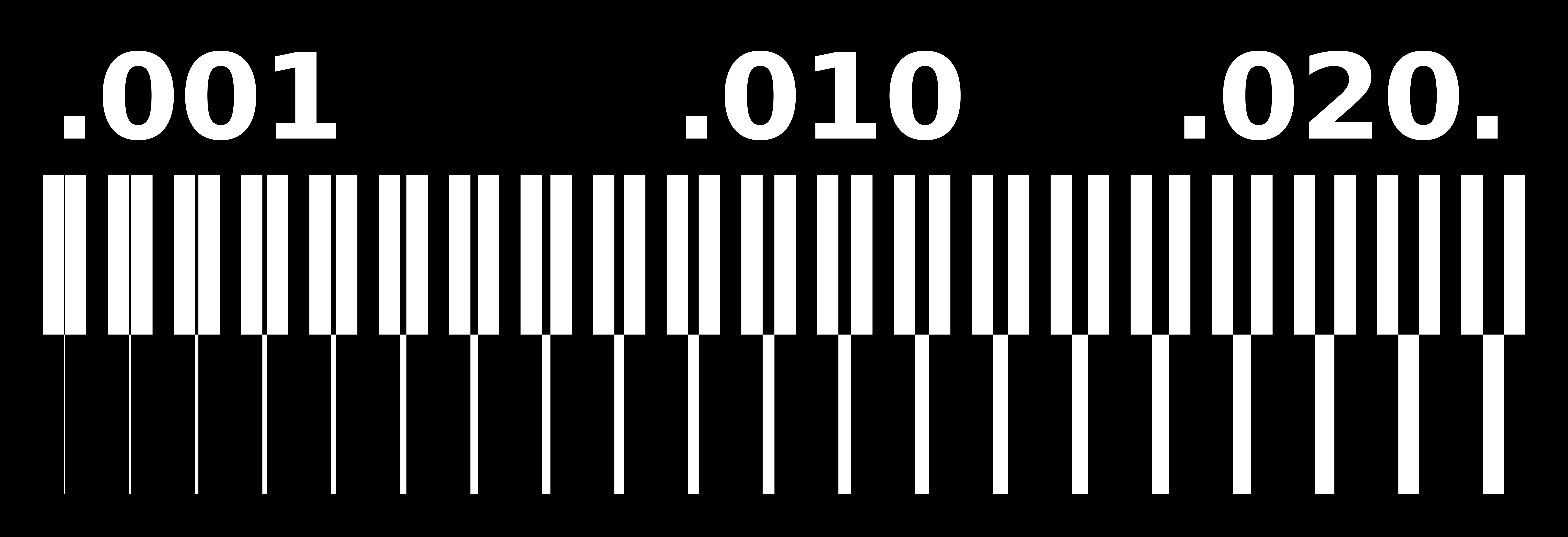
Pin numbering is not very straightforward for the XIAO RP2040, the figure by Adrian Torres is very helpful:
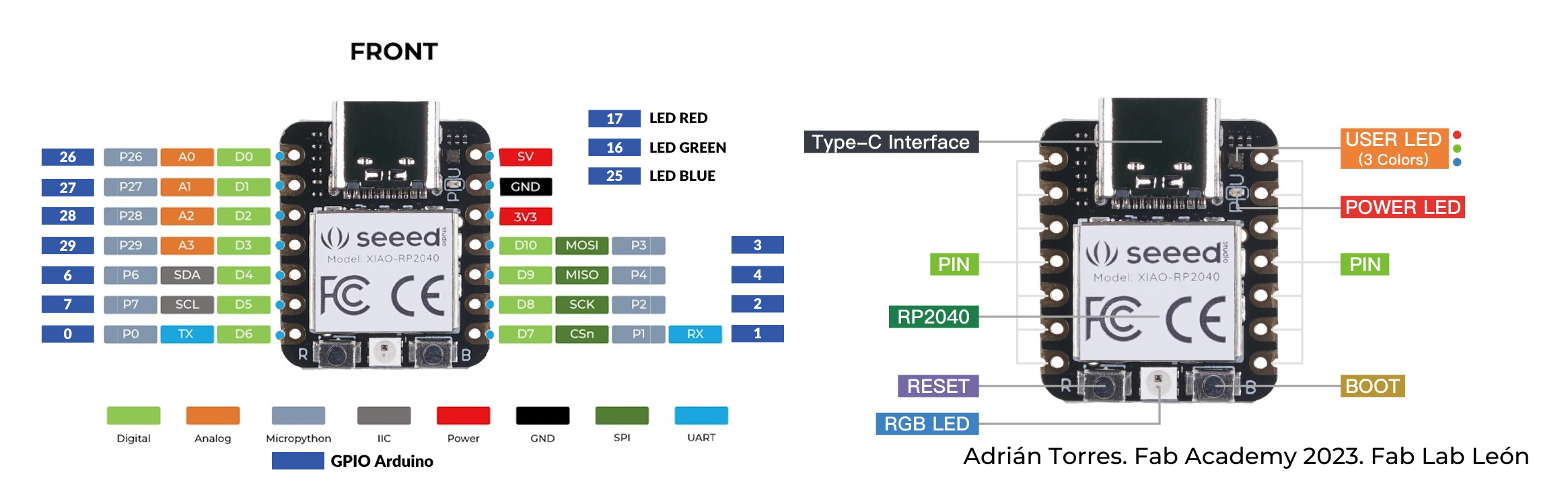
The program is compiled and programmed using Arduino (1.8.19):
board house send-off
Not as part of the group assignment or individual assignment, but I happened to have to Kicad designs ready for production. I usually order with Eurocircuits (for fast delivery) and JLCpcb (when I want cheap, slower and care less about our environment). Leo suggested Aisler, so I also gave that a try.
order a pcb at aisler
checking out the work at aisler
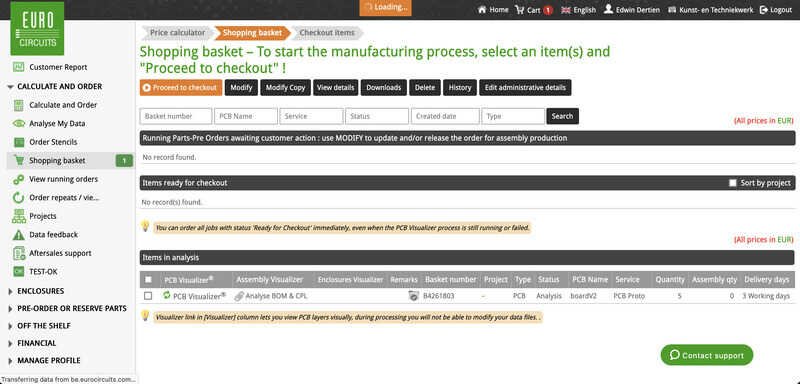
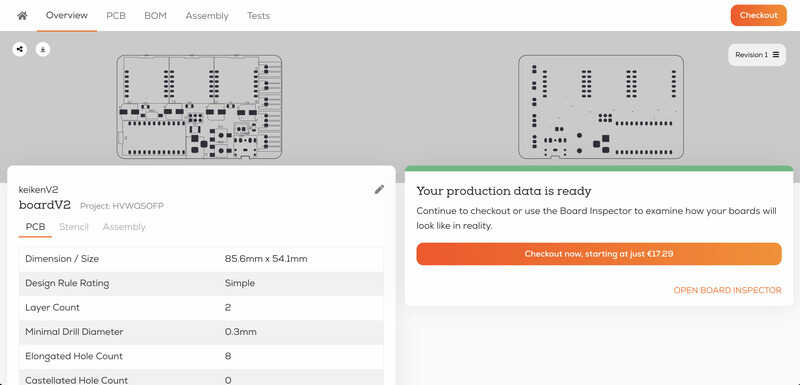
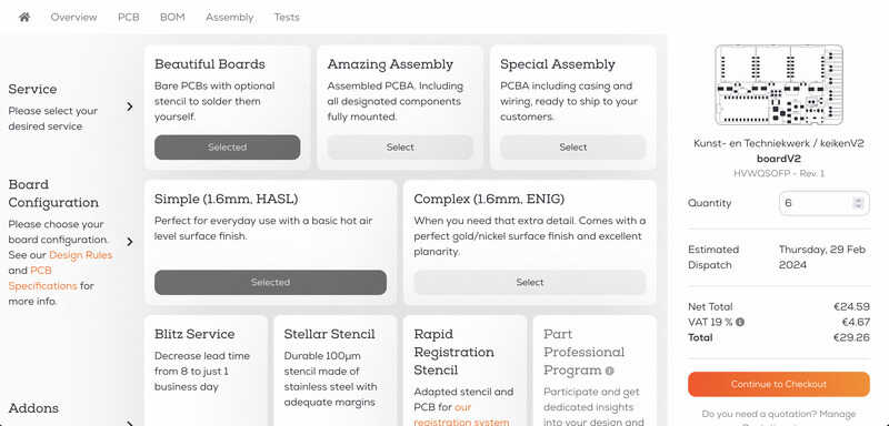
order a pcb at eurocircuits
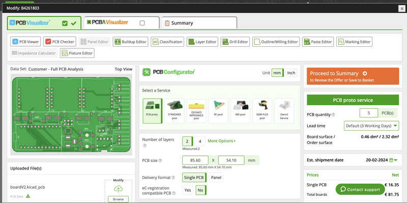
board analyser at eurocircuits
It is very nice that with both houses (Eurocircuits and Aisler) you can send the KiCAD pcb files directly. With JLCpcb you have to prepare a zip file with all gerbers:
- copper layer top
- copper layer bottom
- solder mask top
- solder mask bottom
- silk screen top
- silk screen bottom
- board outline (edge cuts)
- drill file
- tool report
Also, a recogniseable outline should be consistently placed on every layer (at least, this used to be the case, currently JLCpcb can do the layer orientation using the layer’s origin). Still, the way you can simply send a kicad board file makes life easy!
hotplate soldering
I did not have any experience with hotplate soldering, but it seemed a very good in-between solution (in between the hot-air-rework station and the reflow oven). I converted a toaster oven using Arduino temperature control to do reflow work, but sometimes it is nice to be able to do partial assembly on-the-go. I ordered the MHP30 mini hotplate for the lab and gave it a go. The board I had ready for population was a ordered board on FR4 through Eurocircuits - a design to hack a wheelchair by replicating the joystick control signals. The project involved is an autonomous weelchair for abilitytech - a student driven project organisation.
The design consists of two DB9 sockets (male, female) to link between the existing joystick cable and control box. A teensy 4.0 (overkill, but we might want it to run a micro-ROS node) controls a digital potentiometer (AD5282-20k dual channel I2C pot) with a number of series resistors to map the ranges to the joystick signals (6V center +/- 1.0V - the system is powered by 12V). Now this AD5282 in TSSOP16 package is the challenging bit to (hand)solder.
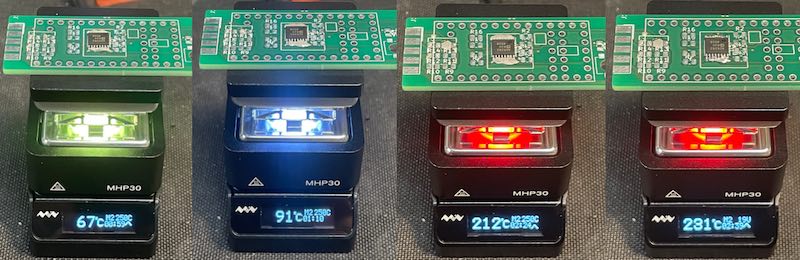
maiden voyage of the hotplate
I overdid the paste (wide nozzle on the syringe) - I found it is better to do careful drips of paste (get smaller nozzle) on a pre-heated board, so next time I’ll heat up the board to 100 deg, then apply paste and drop on the components, (the reflow oven style ‘soaking’?) and then go for the quick 250 spike to solder the components in place. Using de-solder wick (and a fresh drop of flux) I removed the excess solder paste and the board is good to go:
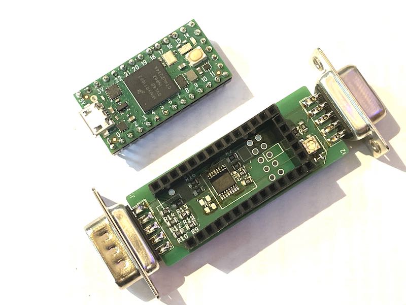
hotplate-soldered FR4 design: Teensy4.0 carrier board as wheelchair - bridge
Bootcamp soldering exercise
The first soldering exercise during bootcamp is to solder 3 programming adapters:
- the UPDI D11C debug wire adapter (with 3-pin socket)
- the Bridge Serial D11C serial programming adapter (with 6-pin socket)
- the Programmer SWD D11C J-tag style programer
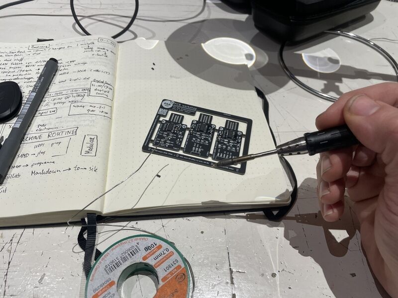
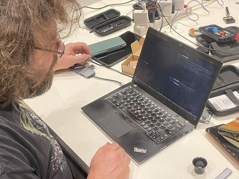
soldering the pcb
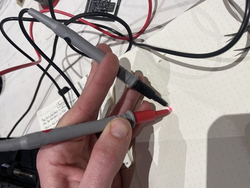
testing the polarity of the LED
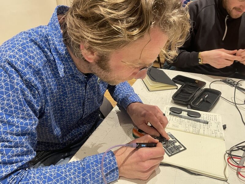
SMD work: I need to bring glasses...
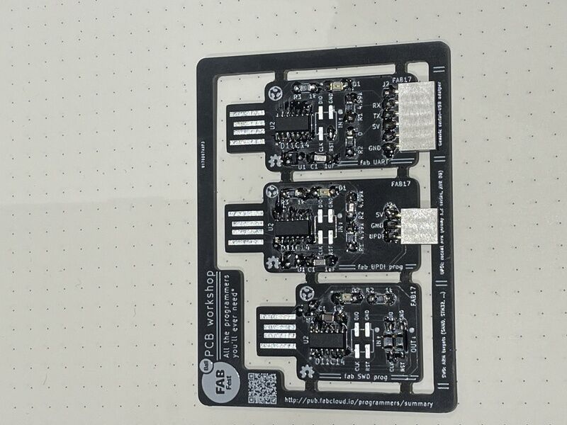
finished work, ready to take out
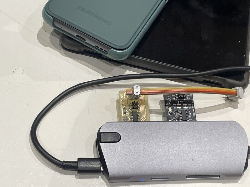
connecting to the PC. USB-C != USB-A
uploading firmware.. the bootstrap
a small piece of 3D printed pla has been attached as filler to the back of the PCB to make sure it fits snug in a USB-A socket. The design file (openScad):
cube([12,10,0.5]);
The first two (after firmware being flashed on Henk’s machine) operate as standard tty-serial devices on macos. The last one needs ‘’edbg’’ on win/linux or ‘‘OpenOCD’’ on macos.
brew install openocd
openocd
seems to work well, the programmer is recognised
learning outcomes
- Described the process of tool-path generation, milling, stuffing, de-bugging and programming
- Demonstrate correct workflows and identify areas for improvement if required
evaluation checklist
The task list for this first week (for personal reference)
- [-] Linked to the group assignment page (referred to colleague page)
- Documented how you made the toolpath
- Documented how you made (milled, stuffed, soldered) the board
- Documented that your board is functional
- Explained any problems and how you fixed them
- Uploaded your source code
- nIncluded a ‘hero shot’ of your board
lessons learned, tips and tricks
(or, the most insightful mistakes I made)
- FR 1 board is not very robust, so re-soldering can easily result in catastrophic track removal.
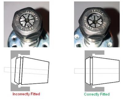
- an unbalanced Spindle motor causes major lack in accuracy. It was possible to mill the board with a single-pass isolation trace, but it is not the preferred way of working. Now I found out (a bit too late) how the collet is supposed to work. Oh well… we live and learn. Next time the board will come out fabulously…
- paste stencils are a livesafer! the used LCD-screen-refraction-foil has the right thickness (0.25 mm) and cuts very easy and precise using the Trotec Speedy 300 CO2 laser. However, it might be that the paste mask is still a bit too thick, or the soldering process with the hot-air rework station needs a bit of work. Some contacts are left with a bit of solidified paste which makes shorts with the ever surrounding (ground) plane. So, either use this proces after finding a way to have a real solder mask. (which protects traces) or mill the board with higher clearance. Especially under components (such as the pushbutton) there should be no additional traces
- the control panel of the 2030pro-max makes life easy!
- Aisler might be a nice option in between eurocircuits (fast, reliable, expensive) and JLCpcb (slow, cheap, larger impact on environment)
left for todo
- redo an accuracy test to check the impact of the (reduced) wobble on the 3020
- for the bootcamp programmers: try to break the serial adapter by flashing it with a blinky - and subsequently reflashing it with FTDI-serial-style firmware
- for the bootcamp programmers: install the SAMD11C14 support for Arduino
- try other production methods (at least soldering on hot-plate and with reflow oven) In the meantime the hotplate has been added, the reflow oven will have to wait a bit.
- I might like to try different materials for paste stencils. I obtained samples of PolyPropylene and PolyCarbonate sheet which might work too.
- find a way to make a good solder mask (not a paste stencil). What about paste stencil -> apply grease -> remove stencil -> spraypaint -> wash away greese -> apply mask again for solder paste….
- set up VS-code to work with the RP2040. Right now the Arduino environment seems to be working ok.
- there is new (open) firmware to install on hot plate and mini soldering iron. Might be nice to check out.
- a bit more work on the grid (bootstrap) css system
- I added a different shortcode for video from this source which seems to work better
reflection
This weeks program was a good incentive to get (my own) 3020 operational. It also helped very much to have been operating and testing the two well-working machines at the Waag, so I knew what to expect. It was quite surprising to me that even with a badly adjusted spindle (ok, the source of the wobble has been found now) still a working PCB could be produced. The amount of reduction in time by using a solder paste stencil were sadly eaten up by the time it took to rework the PCB looking for shorts. Especially when much of the copper is left (as one big groundplane) - especially under components paste will stick and cause shorts. The small hotplate is a welcome addition to (all of the other) soldering tools currently available in the workshop. Fun to see they re-used the menu system from the TS80 mini soldering iron, and that for both there is not an easy way to set the thing at ‘standby’ or ‘cool down’.
copyrights and references
- the XIAO images from the quentorres github repository have been re-used for convenent reference.