Computer-Controlled Cutting
intro
The topic of this week is computer controlled cutting. In most fablabs for this specific topic foil cutters and laser cutters are the main tools to consider. This week the foil cutter will be explored by -just- cutting something, for the laser cutter we go more into depth, since for many (most) applications you have to take into account the kerf (cutting width) and material thickness of the cut made by the laser.
what is it that 'laser' and 'parametric' always cry out for platonic solids....
Group assignment: Goals of this week are:
- Characterize your lasercutter’s focus, power, speed, rate, kerf, joint clearance and types.
- Document your work to the group work page and reflect on your individual page what you learned.
Individual assignments Goals of this week are:
- Design, lasercut, and document a parametric construction kit, accounting for the lasercutter kerf, which can be assembled in multiple ways.
- Cut something on the vinyl cutter.
group work
intro
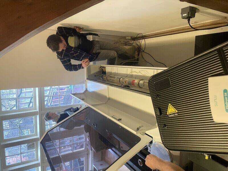
In FabLab de Waag, Amsterdam, the main laser is a 150 W, 120x85 cm BRM90130 CO2 laser. (weighing just 400kg, respect for the people hoisting it up to the second floor of a medieval building without crashing through the floor) In my FabLab in Oldenzaal we use two Trotec Speedy (100 and 300) 40 Watt CO2 machines (which I have used for one of the parametric construction kits) and finally at home I have a new Genmitsu L8 40 Watt solid state laser (which I have used for the second parametric construction kit) In the Lab at the waag there are also two foil cutters (Cricut and Roland GX24) which are demonstrated.
laser setup
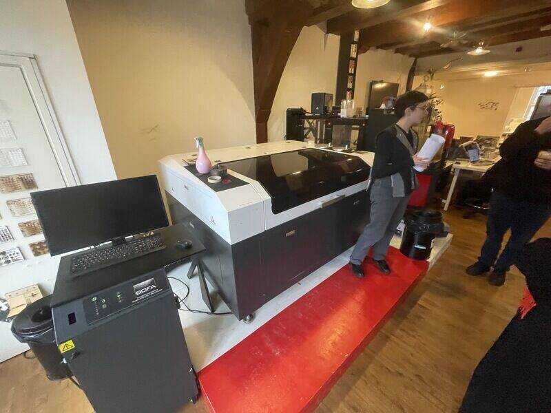
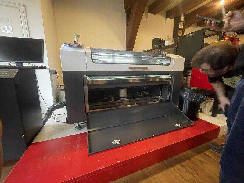
the BRM90130 'workhorse' at Fablab Amsterdam
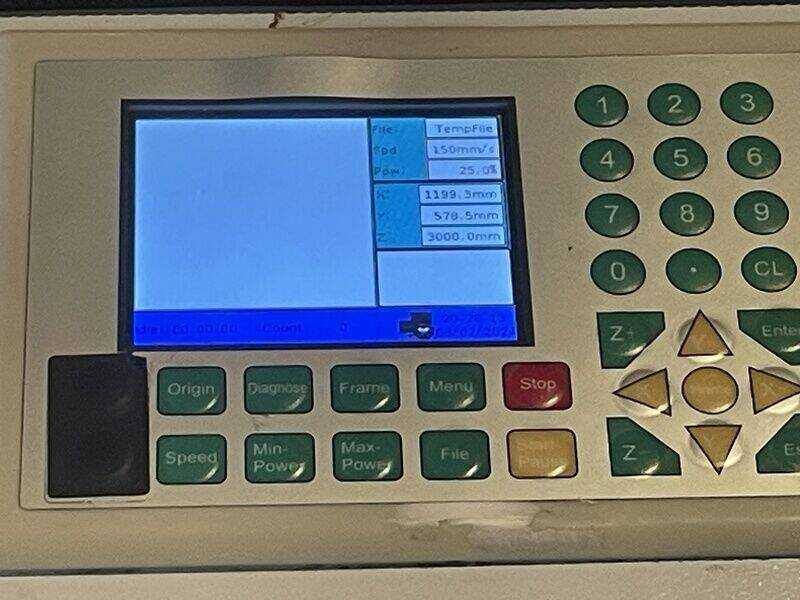
the control panel on the machine (which you hardly ever need to use)
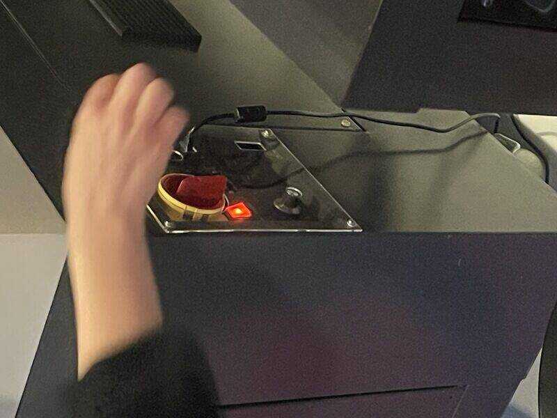
turn on switch, hit reset ...
the 150W CO2 laser tube at the back
front panel to access Z-axis motors
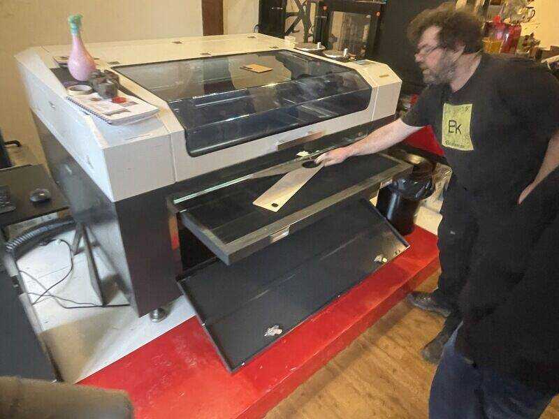
honeycomb bed can be taken out for cleaning
The following two units should make a noise as soon as the machine is started up: the air-assist pump (for blowing out flame and allowing your laser, well, to cut (not to burn)) and the water cooler which is there for cooling the laser itself. The BOFA fume extractor has to be turned on separately for every job (so make sure you have three humming and sizzling units)
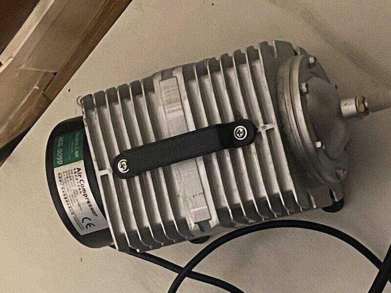
air assist pump to blow out flame
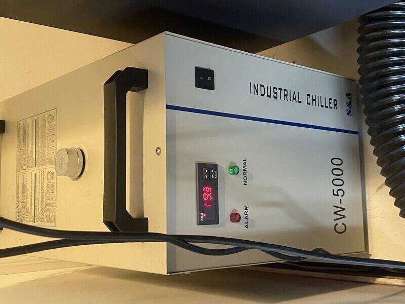
water cooling unit for laser
Job control is done by Lightburn, the PC (below the laser) takes a USB stick with your design files, to be opened on the machine.
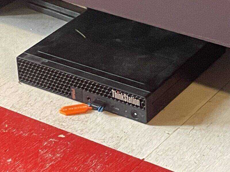
PC controlling the laser. Not-networked, use USB stick
Lightburn control software
Focus the lens using the focus tool. Minimise the need for using the Z-axis, you might damage your honeycomb
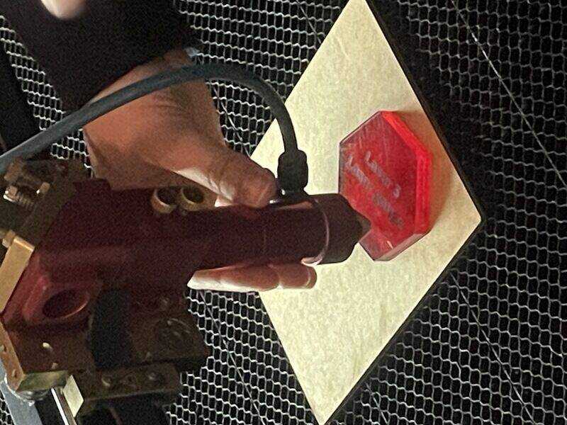
focus tool, manually change Z-axis with two thumbscrews
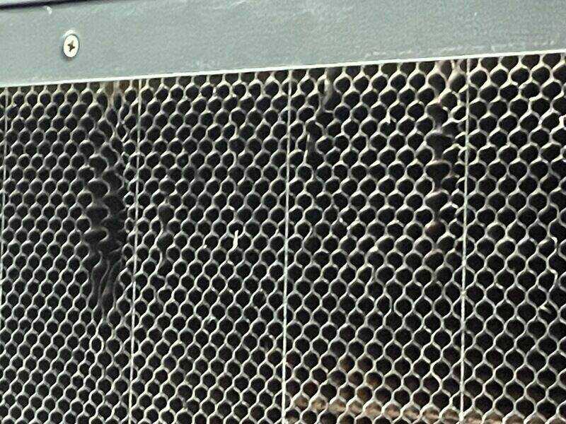
This is the result of the common honeycomb moth (Tineola Ferruginea vulgaris)
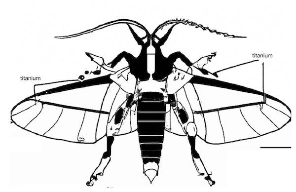
- Genus: Tineola
- Species: ferruginea
- Common Name: Common Steel Honeycomb Moth
needs to be cleaned out regularly
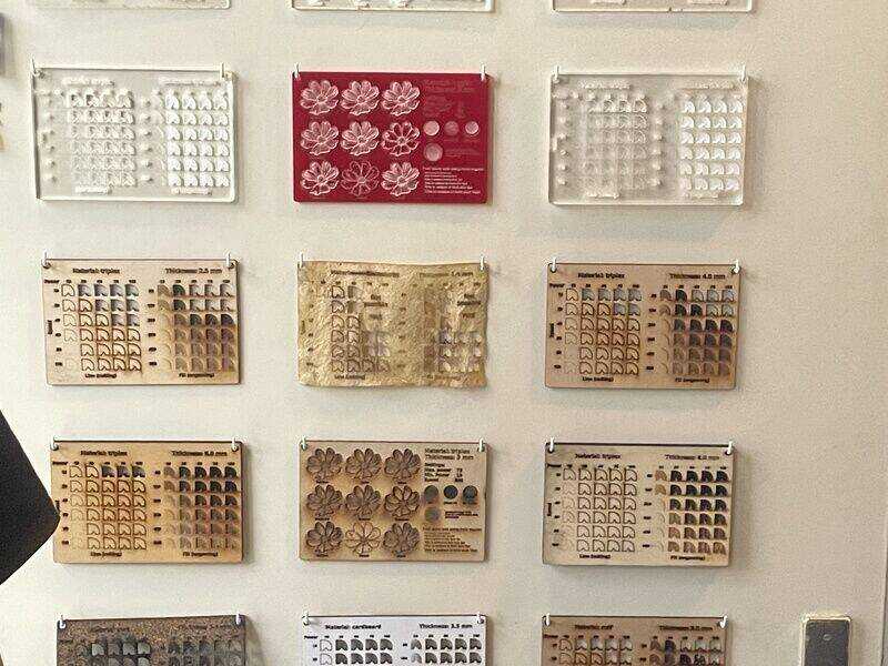
material samples as reference for cutting speed and laser power
safety issues, tips and tricks
- stay in the safety zone / box during cut. (you -are- setting something on fire)
- have a good fire extinguisher standby (blanket, water spray can, CO2)
- make sure there are three humming things: air assist, laser cooling and fume extraction
- be aware of homing (and objects on the bed). Upon reset a laser cutter -will- home!
- keep protection (lid switch) on at all times.
- clean your laser (debris under bed weekly, lens daily, mirror weekly)
- fixing things on the bed with weights: do a ‘framing test’ in lightburn. Note the adidional swing when engraving
- no focus? lens might be flipped.
- weird cornering? lens might be loose
- coordinates / homing: make sure to start from current position (not home) -> then also don’t adjust the coordinates on the machine but stay on computer for moving the head
- bottomline (by Henk): machines are stupid, you need to supply the thinking yourself.
using lightburn
- check for outlier shapes (cmd -a)
- for tester pieces there is something called ‘powerscale’ but lightburn also has its own testing file
- as pre-flight checks there are the preview, and a ‘frame’
- after ‘get coordinates’ you can ‘show current coordinate’ (although, when you start your job from current position, it does not matter)
- check the right box for origin setting.
- material templates on the wall -> use as check, the material settings might not be up to date
- other pre-flight routines to fix a drawing: ‘delete duplicates’ and ‘auto join’
kerf test
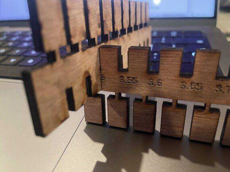
The ‘kerf’ of the laser is the path it burns away in the material, typical a (few) tenths of a millimeter. When you would like your part to be perfectly sized, especially with clamping or a slotted connection, you need to take the kerf into account. In order to measure the kerf (and to measure push-fit clamping) the following piece has been designed using OpenSCAD:
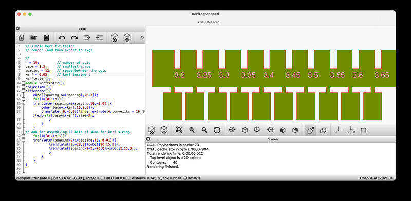
kerf test pattern
The design file is this one: kerftester.scad (save as -> open with openscad)
After finding correct cutting settings (on a wall-template) the file is put in lightburn and cut on the BRM machine:
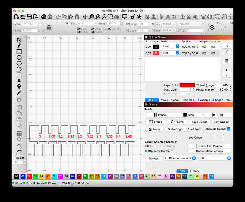
lightburn settings
file after cutting
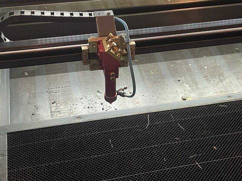
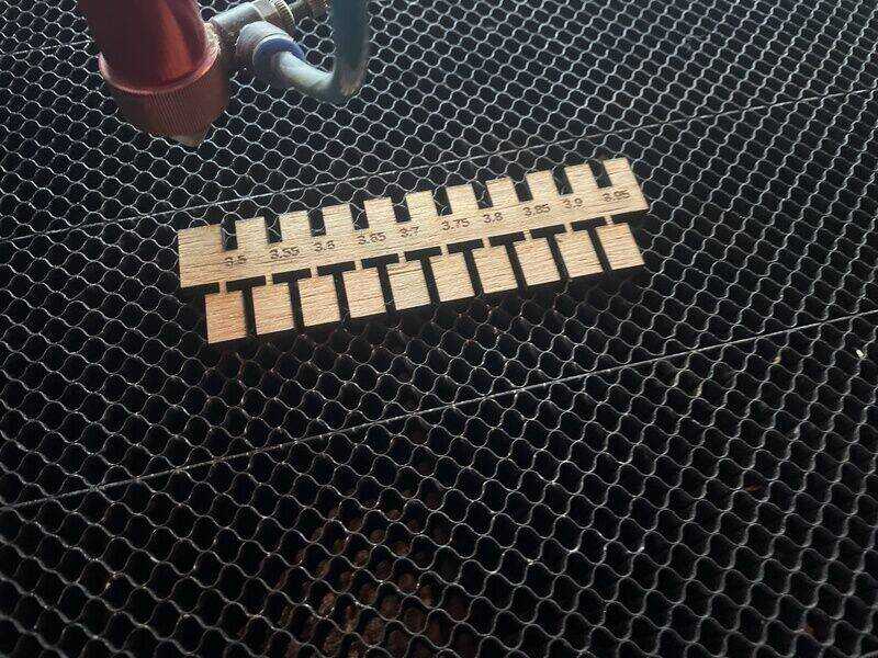
Using a small bit of scrap wood the shape is cut on the BRM
brm laser cutting the kerf testing piece
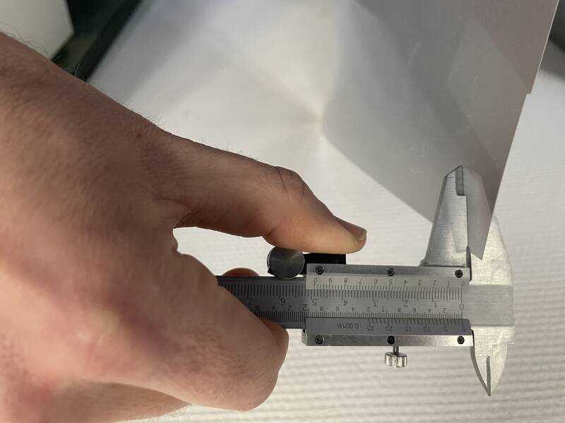
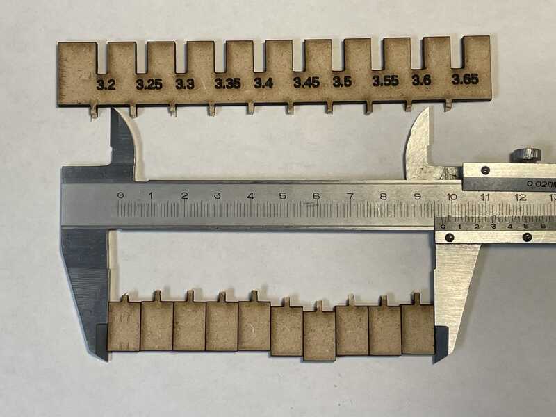
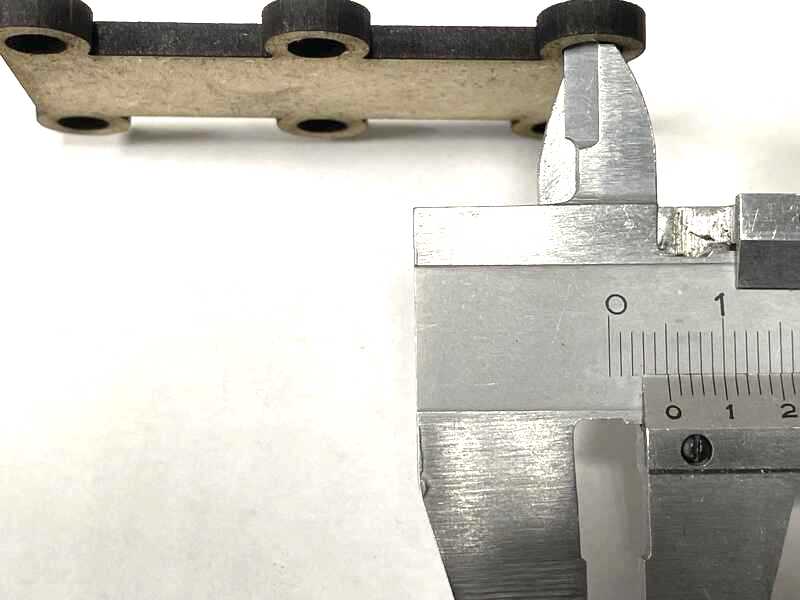
After which the kerf can be measured by snapping of the blocks (snap to prevent dropping through the comb)
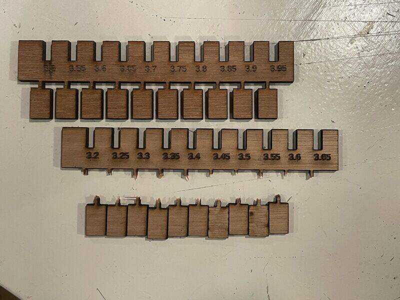
snapped off bits for kerf size testing
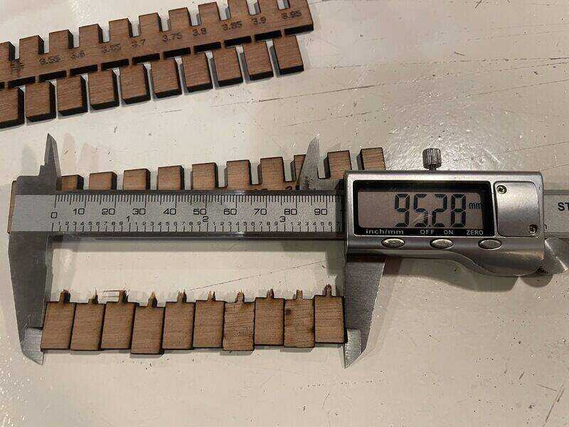
calliper's verdict
For the first go the measurement was 95.3 mm (which was relatively low, resulting in a wider kerf than expected). After cleaning the lenses and adjusting the focus depth, a consistent measurement (also verified by Vera, Leo and Joe) was 97.0 mm for 10 blocks, resulting in 20 half ‘kerfs’ in 3.0 mm, or 0.15 mm as advised kerf-offset in your drawing.
The other bit of the described design allows for a quick material thickness / clamping force check:
press-fit test - always smaller than expected
focus test
For the focus test the drawing of a line is used, printed on a piece of cardboard which was placed under an angle in the machine.
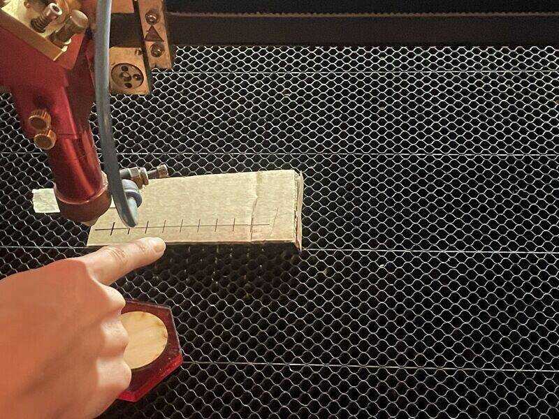
first go
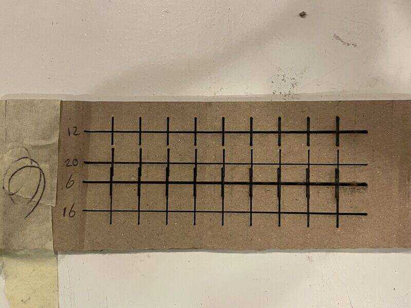
four different heights offsetting the Z-axis
the angle (during this initial test) was simply set by folding the last bit of cardboard under a 1 cm high angle. Since the best point is measured afterwards anyway, it does not matter much in terms of absolute position, as long as the relative position to the z-axis can be measured.
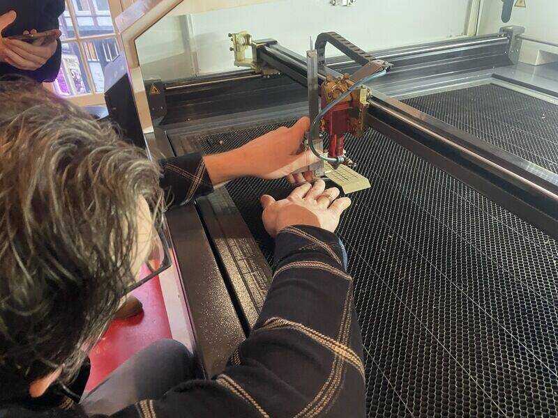
measuring the focal distance for the best (sharpest) point on the best line
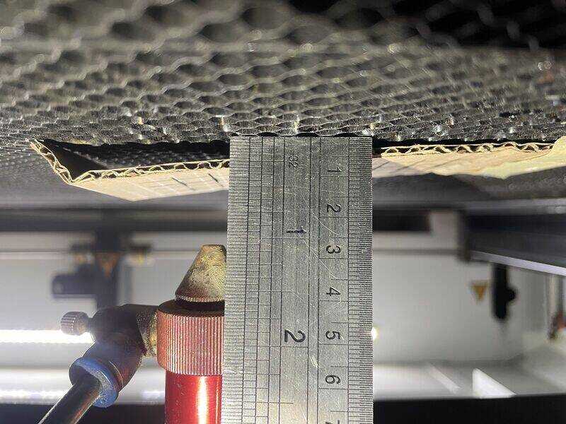
2 cm as focal point for the best curve-point (of 4)
The focus drawing (line) is drawin using inkscape: focustest.svg (save as -> open with inkscape)
Roland GX 24
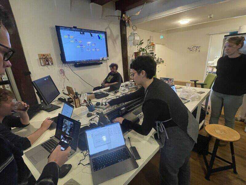
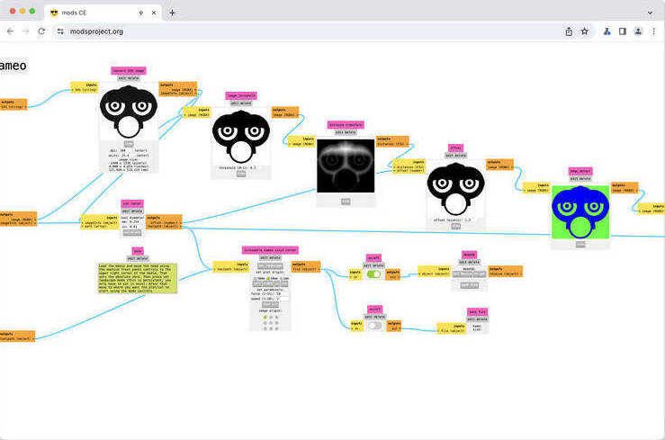
The Roland GX 24 foil cutter can work with materials up to 24’’ in width. Typically vinyl on roll. The control can be done using the in-Fab-developed modsproject. Note that for processing the data any browser is suitable, but for controlling a cutter or CNC machine using (USB)serial, (webserial) a browser such as Chrome or Chromium is necessary.
brew install chromium --no-quarantine
brew cu
xattr -cr /Applications/Chromium.app
roland foil cutter setup
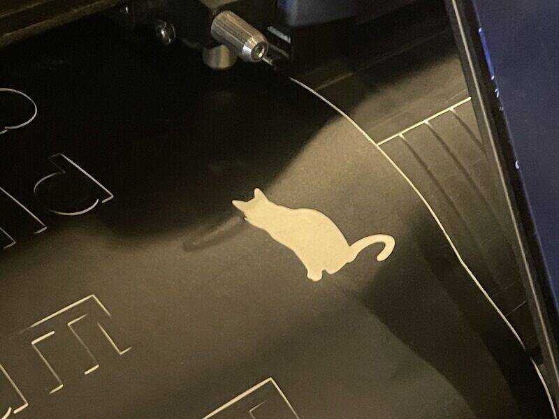
roland foil cutter result: white cat
Cricut
The Cricut foil cutter works with proprietory software (with apparently encrypted data transfer) so no control with mods. The tooling (software) is sufficient for simple tasks
circuit foil cutter setup
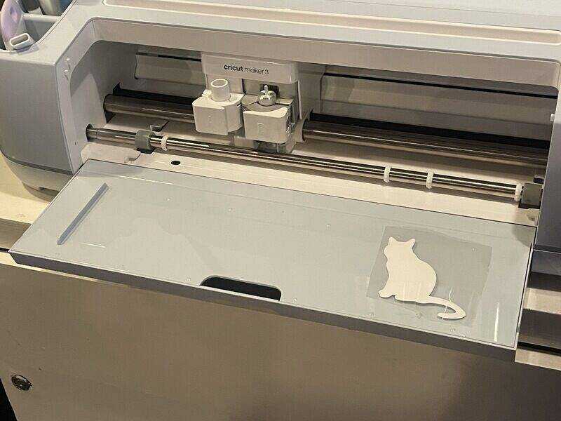
circut foil cutter result: white cat
Eventually this type of plotter is the most likely candidate to manufacture pcb’s like this one:

PCB manufactured on circut plotter in Fablab Amsterdam
individual work
The individual assignment has been carried out at Fablab Oldenzaal - and partially in my home-lab.
foil cutter
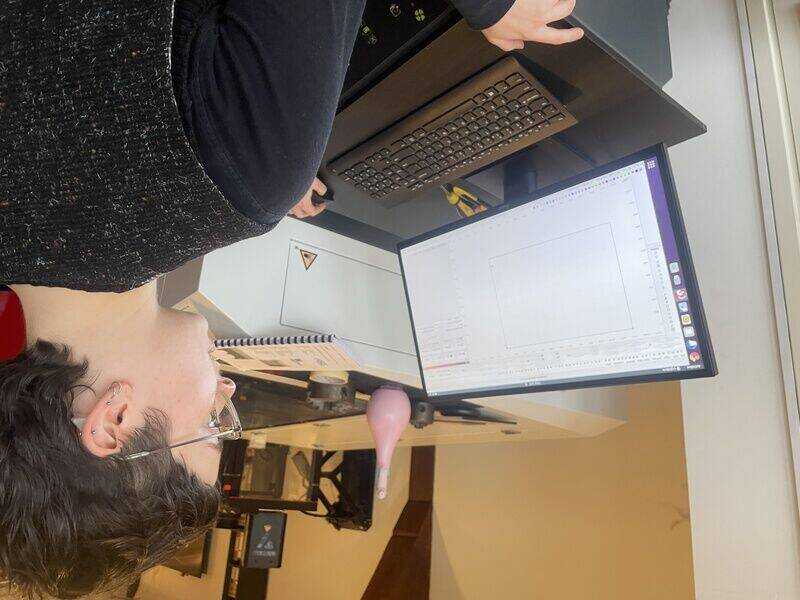
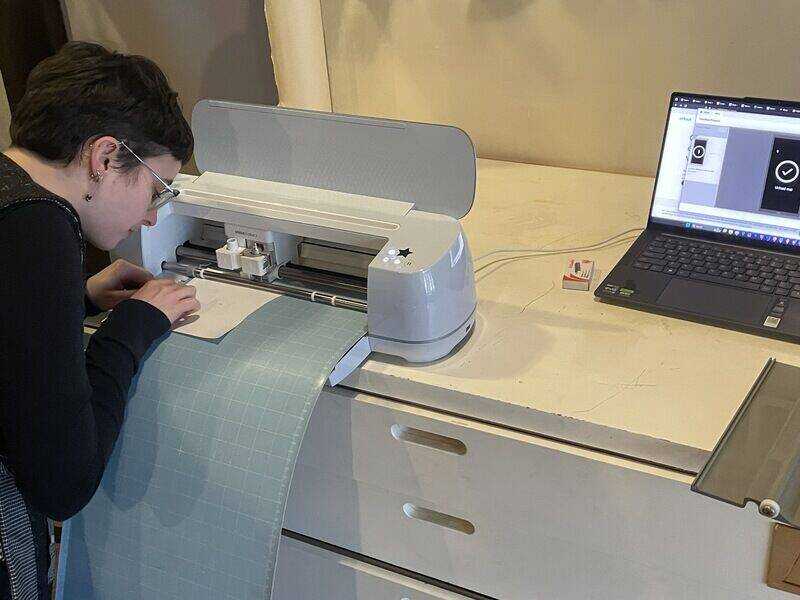
The work on the individual assignment has been carried out on a Silhouette Curio foil cutter, which has a small (A5) and larger (A4) ridgid bed (different from the Silhouette Cameo which has a larger, flexible mat)
Silhoutte Curio at desk in home-lab
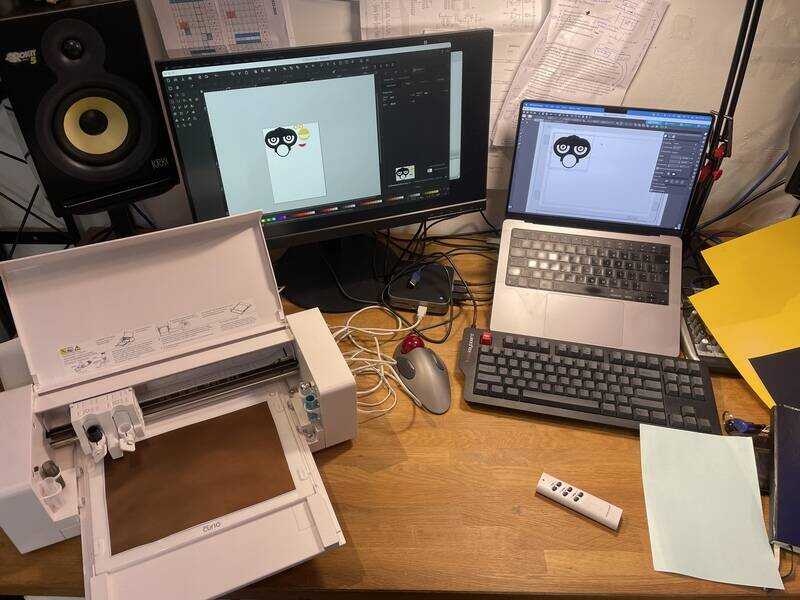
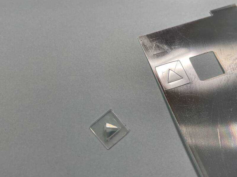
test cut of square-with-triangle
- design traced and modified with inkscape
- silhouette studio only accepts png (so manual scaling)
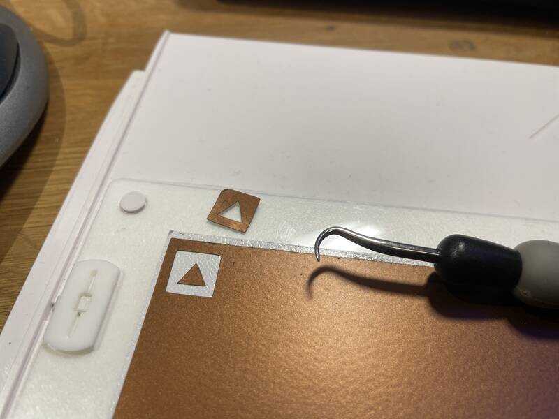
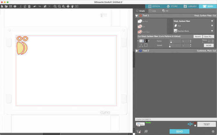
- edit cut settings:
- vinyl foil: speed 10, pressure 5, knife 1
- copper foil: speed 1, pressure 2, knife 1
- plastic 0.25mm refraction sheet: speed 1, pressure 33, knife 10, 2 pass
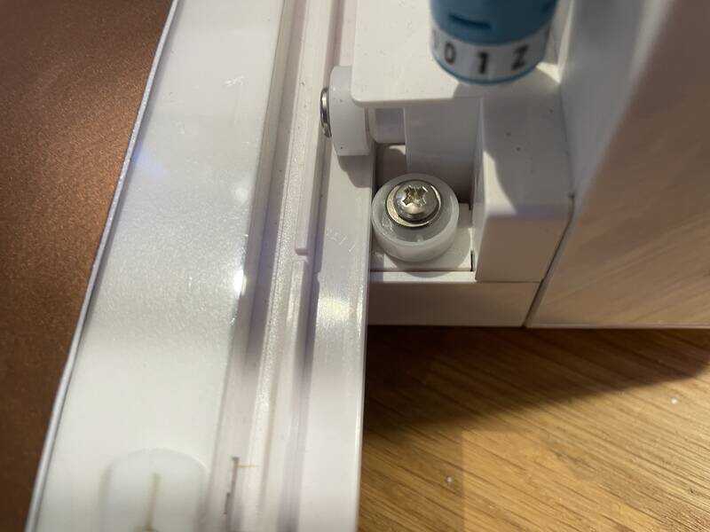
put in bed until the mark is alligned with the edge of the machine
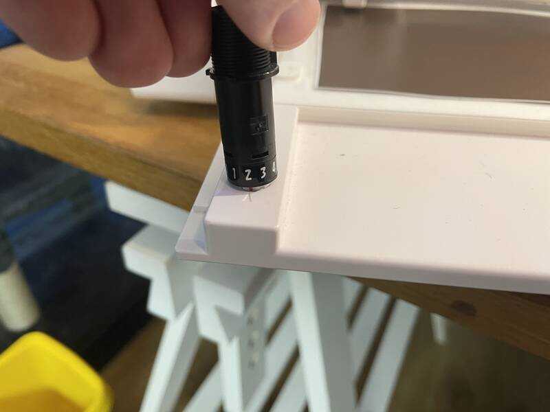
adjust the blade depth
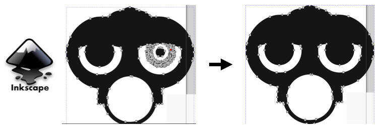
shape point reduction after tracing in inkscape
Silhouette studio does quite a good job, downside is it cannot work with *.svg directly, so you have to export a *.png from inkscape.
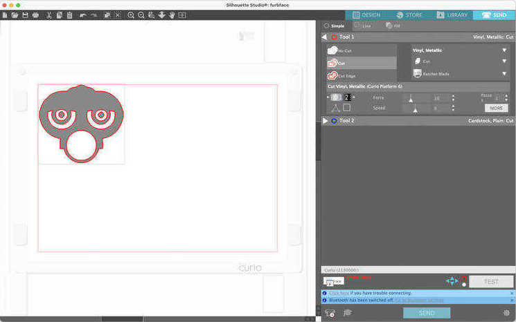
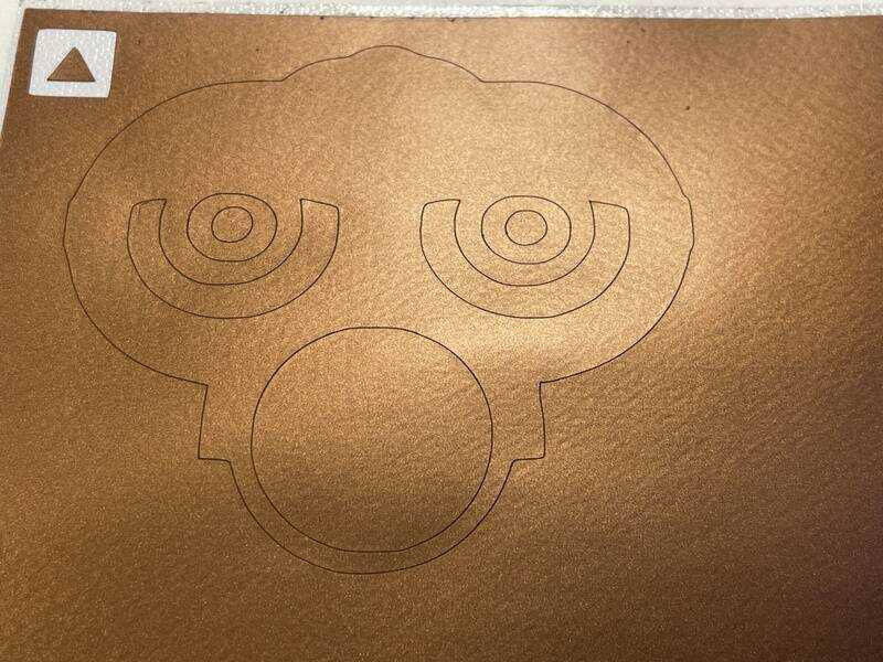
Traced (again) in silhouette studio
second layer for copper foil
Cutting the copper foil was quite challenging and went wrong on the first try:
Cutting copper fail (failing...)
- conclusion: low speed, very low pressure, fix tape well!
other hints and tips to increase stickyness:
- rinse cutting mat with soapy water
traced (again) in curio
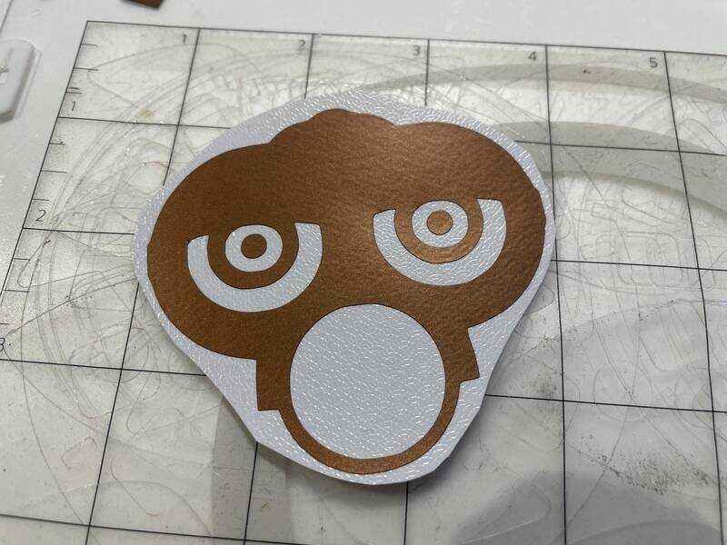
weeded sticker
transfer foil cut to size

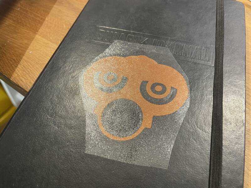
The end product: a furby face with full-metal-beak on my notebook
- try with mods: first install chromium: not trivial on mac. Also as additional test I tried to cut the heavy (PET?) foil which I also used for the parametric toolkit design (explained later). With quite heavy settings (33 pressure, 1 velocity, 2 pass) it managed to cut -something- but not convincingly.
try with mods. test cut works, rest sadly not(yet)
test cut of heavy PET foil. not convincing
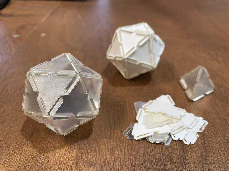
kit #1
Based on a great idea by Maarten (one of the participants at Assortimens / Fablab Oldenzaal) who started to make geometric platonic solid shapes using the refraction foil from scrapped LCD monitors. Finally something cool to do with this foil! (we have been stockpiling it, we typically use the big 8mm acrylic sheets, but hadn’t found a purpose for the shiny foil…)
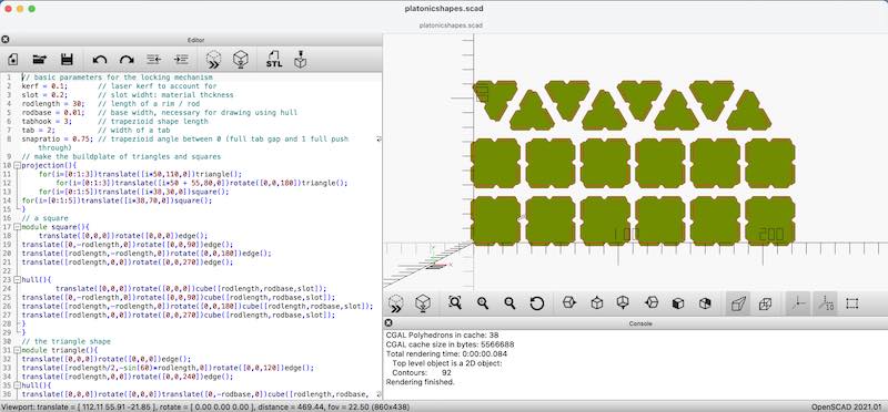
openscad drawing. the drawing can be produced as 'ready to cut'
- the design file (right click save as .scad)
The locking pattern consist of a tab and a slot, next to each other on one side of a triangle or square (or other regular shape). In OpenSCAD a parametric drawing has been made to allow for kerf, foil thickness, tab angle, etc.. in order to find a good balance between locking effort and fixing power.
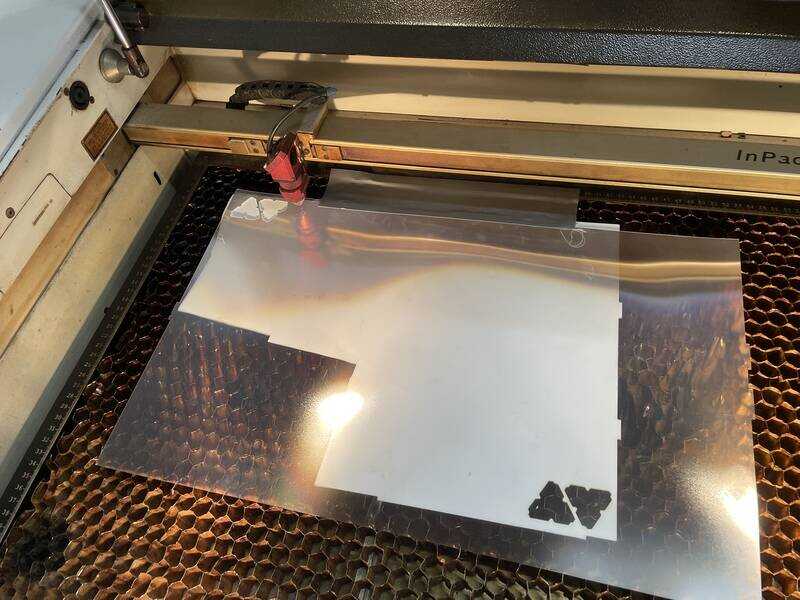
refraction foil with protection foil underneeth
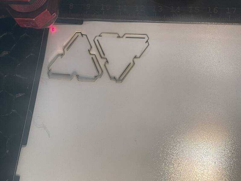
triangles being cut
After cutting the first two, I needed to check and verify, also taking into account the thickness of the foil and the resulting kerf to adjust the drawing in OpenSCAD. After that I did cut the ‘big batch’
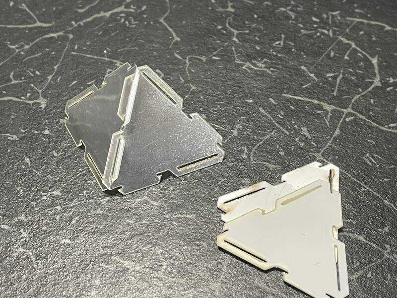
first test of fitting the triangles
checking the thickness to be included in the OpenSCAD file
Trotec laser at work
In a next iteration I just generated two drawings with OpenSCAD and let deepnest take the strain of fitting enough on a printbed:

used workflow
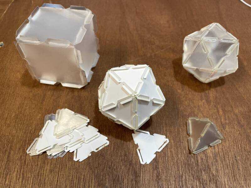
cube, triangles, tetraeder, icosahedron
icosahedra, tetraeder
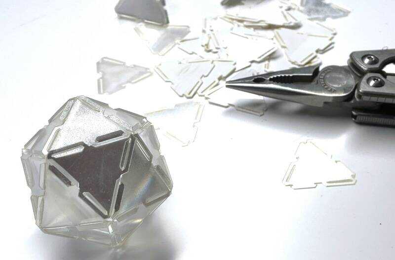
result. needing pliers for slotting the last triangle in place...
After the first tetrahedron the quintessential icosahedron :). More shapes (squares, rhombicuboctahedron) to come (because I want to get on with kit ide #2)
kit #2
Goal of this set is to try a different locking mechanism in wood, with a clamping peg & hole system that allows for rotation (I want to build small posable figures and robots). Additional goal is to use this set to set up and test a new Genmitsu 40W L8 solid-state laser.
The idea starting the design in OpenSCAD was to design something that could help build a small legged robot. Inspired by the fantastic designs by robotime, I wanted to design something that allow for posable joints.
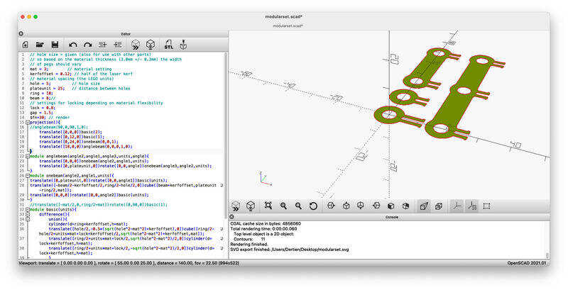
first go in openscad
- the design file modularset.scad (right-click, save as)
In the design the width of the clamping piece (typically 4 mm) depends on the hole size (fixed at 5mm) and the material (typically 3). (3^2 + 4^2 = 5^2). Besides this dependency on material thickness, I also want to account for the kerf. In the following picture you see the change by setting wall thickness and change with the kerf:
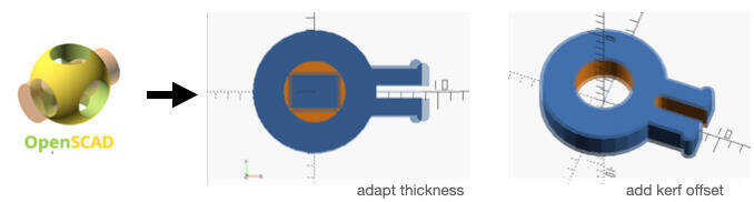
changing thickness and kerf
Next up, the set-up of the machine:
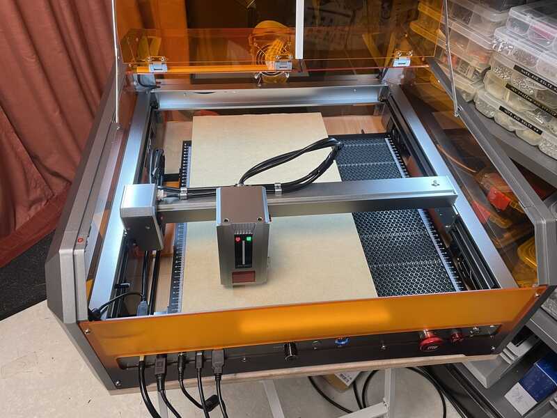
the genmitsu L8 solid state 40W laser
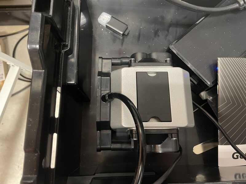
air assist pump
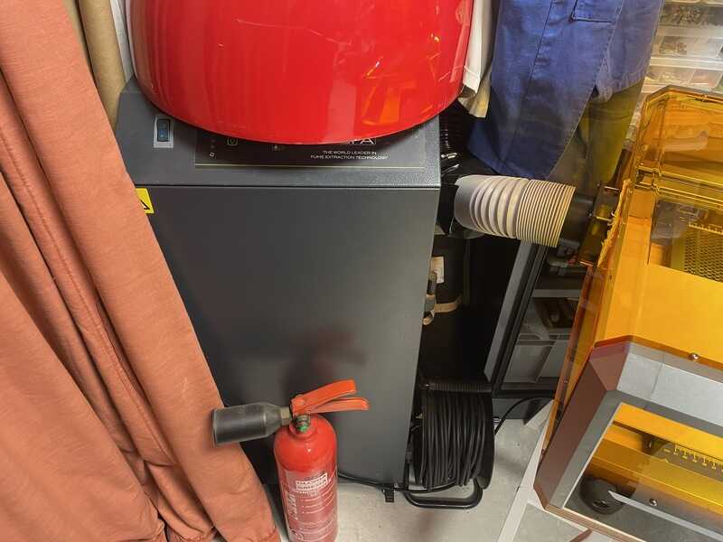
extinguisher and fume extractor
First: material settings and kerf test:
kerf testing bit on Genmitsu
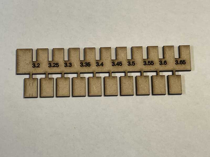
kerf test
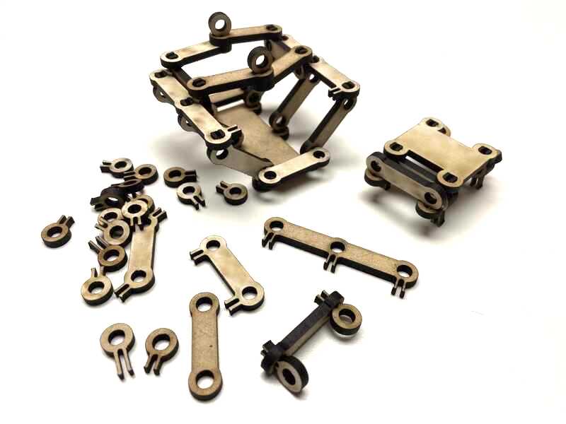
The first set cut of a few parts:
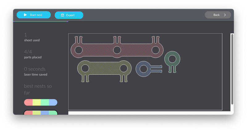
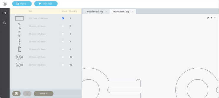
parts in deepnest
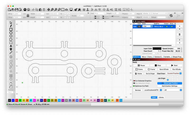
parts in lightburn
The workflow in this case allows for ommiting inkscape: Lightburn can work with the deepnest file directly:

workflow with deepnest and lightburn
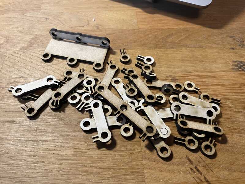
The resulting cut work:
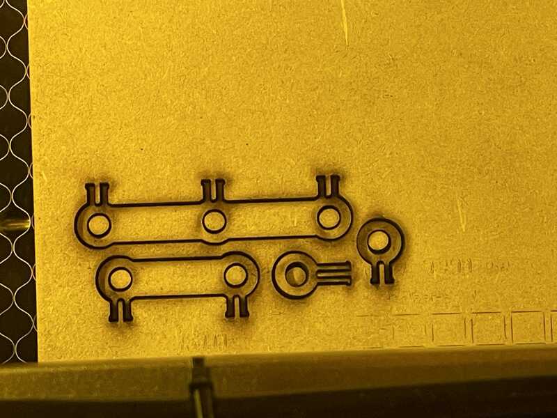
first try
quick check for fit
- Note (by Henk) - the material might be MDF, which is quite toxic to cut see this link so please check with GlowForge what their ‘draftboard’ is made of.. glowforge has added a warning for CA Residents… It does not say it is ‘mdf’.
Now ‘ordering’ the parts in deepnest:
menu in deepnest to select number of parts
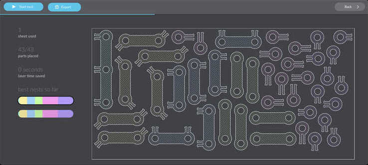
the nested build-plate
genmitsu L8 laser at work
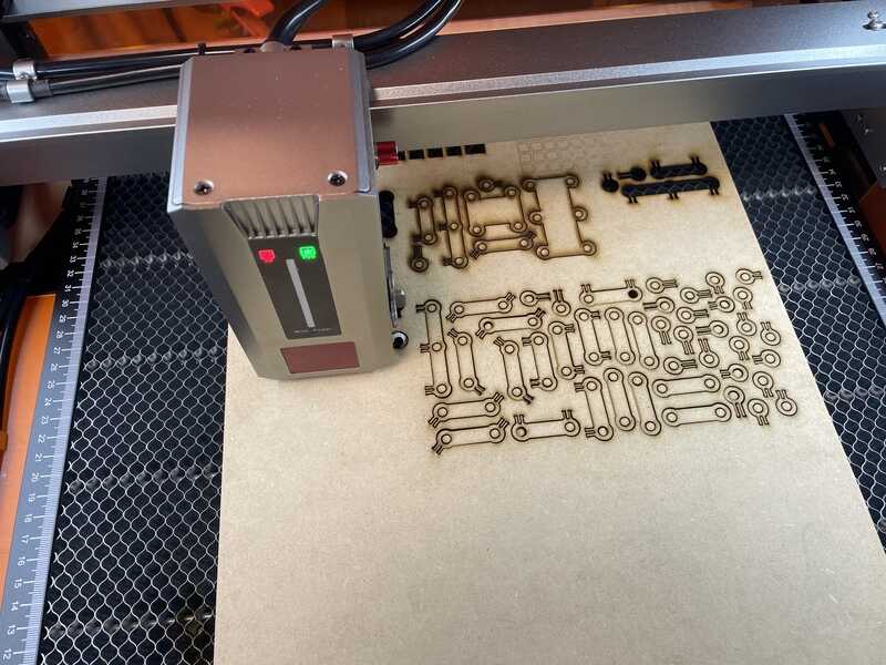
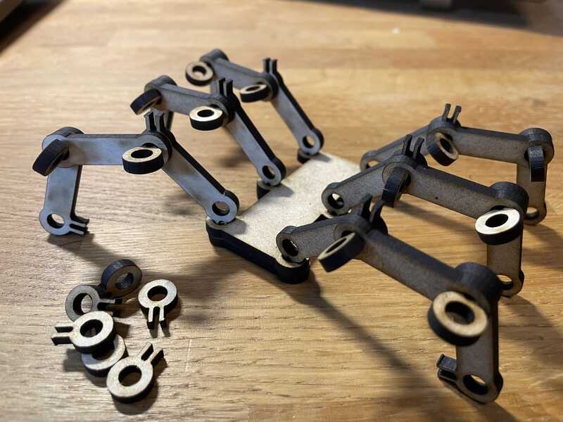
full set in the cutter
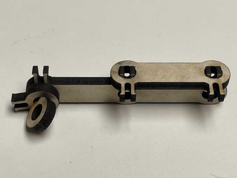
play time!
still some quick checks…
thanks to the kerf: spot on 5.0mm
almost an insect
the parametric construction kit
Eventually the connections are posable, but still a bit ’loose’. It might be possible to design a T-piece or wedge that can slot in the clip, in order to lock it (or adjust the friction). Anyway, this might be something for a next version:)

and... done!
learning outcomes
Task for this week is a group assignment on laser characterisation and individual work on a parametric modular construction kit (oh, and something on the vinyl cutter)
- Demonstrate and describe parametric 2D modelling processes.
- Identify and explain processes involved in using the laser cutter.
- Develop, evaluate and construct a parametric construction kit.
- Identify and explain processes involved in using the vinyl cutter.
evaluation checklist
- [-] Linked to the group assignment page. (instead displayed on this page, not on a separate page)
- Explained how you created your parametric design.
- Documented how you made your press-fit construction kit.
- Documented how you made something with the vinyl cutter.
- Included your original design files.
- Included hero shots of your results.
lessons learned, tips and tricks
- Deepnest is a very helpful tool for laser sets using many parts. Definitely one that stays in the toolbox
- offsetting for the kerf in a drawing is not that complicated and helps making spot on-precise parts. So lets keep doing it :)
- clean your laser often, regularly!
left for todo
- work on a small T-piece to lock the small clamp in construction set #2
- find good locking/gluing? for copper tape
- find (check) a good materials list. Apparently anything is toxic if lasered long enough. Knowledge on hazard and toxidity might vary from lab/space to space, so that’s something to look into for my own lab
- check how the genmitsu L8 can be cleaned (if necessary)
- get mods to work with curio and gcc. I suspect it is something in the pipeline/program example rather than to do with the plotter control (which is -just- HPGL I expect)
- check how to break my GlowForge and set it free by removing the proprietory control stuff…
- check Inkscape’s plugin for the silhouette
personal reflection
Busy week. It was nice to develop tools for characterisation for an existing machine, and subsequently use them on my ’new’ machine. Also taking into account the kerf results in very precise parts - although the fitting/clamping itself is not directly related to the kerf and material thickness alone.
The group project resulted more in ‘parallel play’ rather than actually well-organised and structured group work. I think part of causing that is (at least with me) that I actually want do (be able to) do everything myself and make sure I understand everything completely. This was by the way mostly the case with the first kerf test - with the focus test (and servicing the laser) we managed to team up better.
Deepnest was a new tool for me, very nice experience to be able to select the number of files you want on your plate (it feels like a free webshop :) - and let the program do the optimisation. Also lightburn was a first (in combination with the Genmitsu L8) - very mature software (So I don’t regret paying for a license).
The end results were not so aesthetically pleasing as some of the other portfolios I have seen online, however, I very much liked the simplicity of the OpenSCAD script (just 50 lines of code) and the versatility of the generated parts. Although the locking can be improved, I like its potential. The triangles / geometric shapes were also a very nice and versatile set of parts (and good re-use of the LCD-screen foil). I like it how after the initial puzzle (sizing and shaping one edge) the process to design other shapes, being able to change sizes and locking parameters works out. If you pay attention to the details enough at the start, it is easier to expand and build upon that later.
For the silhouette curio (and other machines to come) I would like to dive further into the modsproject, however I didn’t manage to get it working beyond a test-cut. Inkcut is also on the wishlist next.