CAD design of the possible end-project
intro
Goal of this week is to model (raster, vector, 2D, 3D, render, animate, simulate, …) the (possible) final project, compress your images and videos, and post it on (this) page, while evaluating and selecting 2D and 3D design software, demonstrating and describing the processes used with these software.
Tortured Furby Modular Synth module
Ok. When we go for the tortured furby module, the following product breakdown structure (PBS) can be recognised (the functional breakdown is already given (partially) in the linked brainstorm page)
final project pbs
The following components can be recognised in the module as part of a Product Breakout Structure (PBS):
| PBS | subcomponent | CAD | production | topic | remarks |
|---|---|---|---|---|---|
| furby synth | full design | blender | animation, video, pictures | week 2 | |
| base plate | parametric, OpenSCAD | laser cutting | week 3 | fit eurorack | |
| articulated furby face | parametric, OpenSCAD | 3D printing | week 5 | add servo mech | |
| RC servo tendon drive | OpenSCAD / Fusion | 3D printing | |||
| user interface | kicad / OpenSCAD | based on PCB allign with baseplate and face design | PCB production | ||
| add furryness | blender | real fabric | … | ||
| eyeballs | .. | 3D print or mill a mold, casting clear acrylic | week 12 |
For the user interface all elements can also be added in KiCAD in 3D (grabcad has a large selection of electronic components rendered, also many of the KiCAD repositories already have nice 3D component designs. )
-> also, can this pipeline be used for other creatures? Think about a Grover (tm) module, or a Yoda / Grocu (r)(tm) module, a darth-vader (but that should be a james-earl-jones vocoder)… anyway….
learning plan:
I am looking for tooling that fits my workflow. I’m not sure at the moment whether I’d rather look for “one tool to rule them all” (or a small set) - or use “any tool that will do the job best”. I like many aspects of OpenSCAD, it turned my head into a rendering engine, but it has also some major limitations. I would also like to (learn to) use a tool to work with organic geometries (think scanning an object, rendering mesh, processing and re-working into a design). Previously I worked with MeshLab for processing scanned meshes, but eventually ended up using Scandy Pro for scanning data and […]
Online and during the session a number of tutorial movies were mentioned (or found) to get started:
- a freecad tutorial
- a meshlab tutorial
- fusion360 tutorials
- blender tutorial
- rhino tutorial
- Cuttle tutorial
I think I’d like to focus on OpenSCAD for my final project rendering (which I have been using for quite some time now, but are nowhere near profficient in/at) with help / a side order of Blender for the rendering. The plan for this week is to explore a number of tools by watching a tutorial and completing a simple design.
| package | tutorial time | design exploration | verdict |
|---|---|---|---|
| FreeCAD | 30 min | 30 min | |
| Fusion360 | 30 min | 30 min | |
| Rhino | 30 min | 30 min | |
| cuttle.xyz | later | ||
| OpenSCAD | designed tut. | 3 hr (benchmark) | |
| Blender | 2 hr | 6 hr | |
| Gimp | – | check layers and alpha blending | |
| Inkscape | – | check parametric design options |
I will leave meshlab for the session on 3D scanning and processing data. My idea now is to explore the listed tools, design the mechanical bits for the final project in OpenSCAD and try rendering / simulating / animating them using Blender. Cuttle might be a tool to check out next week for parametric cutting. Also for parametric cutting I think I would like to give OpenSCAD or an Inkscape extension a go, the FreeCAD options for (over)constraining drawings brought back bad memories of early SolidWorks (‘99) design projects.
For Inkscape I would like to explore some extensions (parametric options) and give gimp another go to see if I can do the basic steps necessary for processing an image into a cuttable file (let’s take a furby photo).
2D exploration
Good options and strategies to look at are ‘automation’ functions or ‘pipelines’. Especially in tools like photoshop, if a series of images has to be processed for a consistent look, ‘actions’ can help to streamline the proces and help out with repetition. First up: basic image processing (cutting and extrusion preparation) using GIMP and Inkscape. The picture to start with is a nicely cluttered furby from The Furby Wiki.
GIMP
In GIMP (no tutorial) I
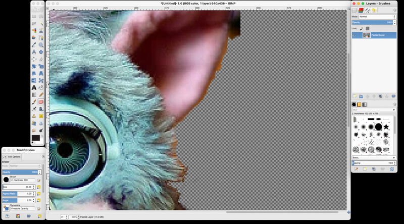
- open a number of tool panes (toolbox, layers, brushew)
- I copy the image unto a new layer
- duplicate the layer (so I’m sure to have a clean background layer I can edit or change later)
- I try the ‘magic’ scissor tool cutting out the image from the background (works not well, not sure how to adjust settings). Magic wand tool also works (brings me back to photoshop 1.5). In the end the fuzzy erasor tool…feel RSI coming up I didn’t feel for 15 year. Time maxed on 10 min.
- I copy it twice, make a white background layer
- I blur, discolorise the middle layer as drop-shadow (for that retro look)
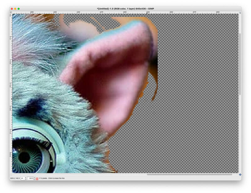
lasso, erasor, work on layers
pixel level editing
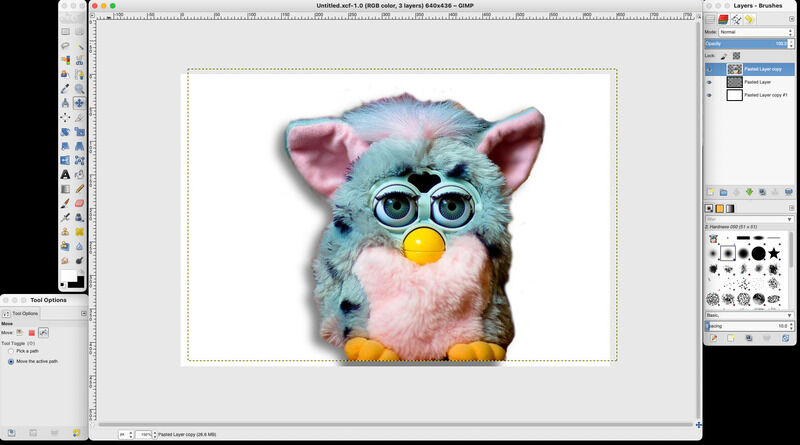
Classic clean cut with drop shadow. hmmm... retro....
Inkscape
Over to Inkscape. I like to experiment a bit with the multicolor trace for next week (foil cutting electrocuted furby T-shirts.. might be worth thinking ahead) In order to trace the image I use
- multicolor trace, 5 colours
- a single scan (outline) to do the shadow
- a single scan in edge detection mode
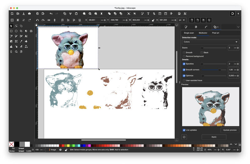
using the multicolor trace (path->trace)
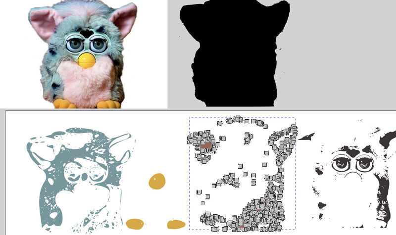
reducing shape complexity with path->simplify
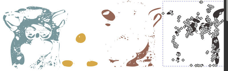
separating layers and simplyfing path

a reconstructed 4-color furby
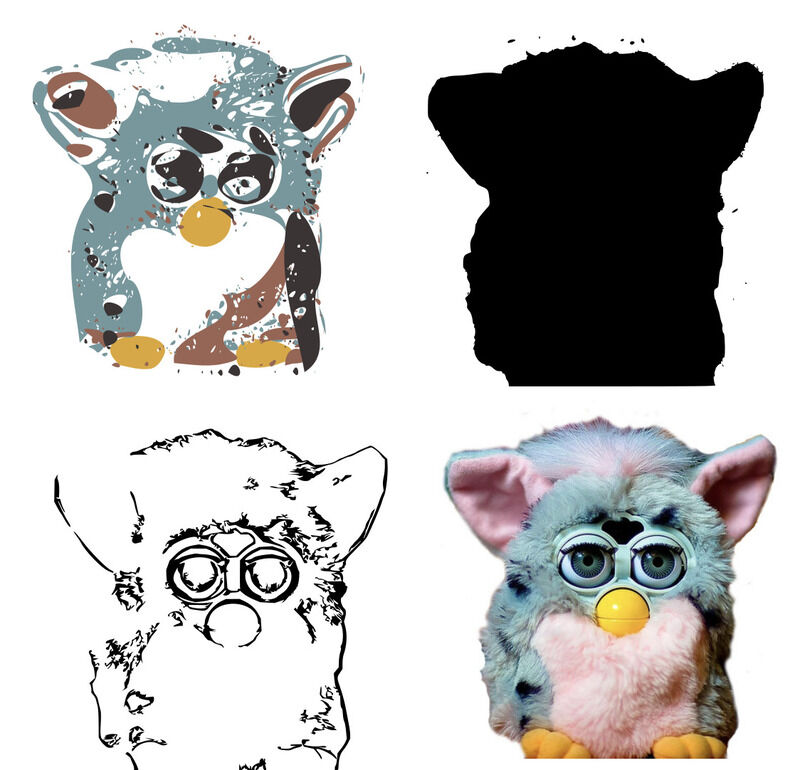
furbies using single scan, mult-color and edge detection trace
Especially the multicolor looks promising for working with foil cutter. However, picture shapes might be too complex. Simplifying the curves quickly renders the image irrecogniseable, while still being relatively complex.
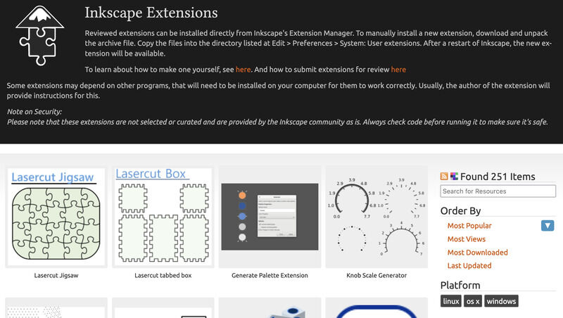
Inkscape plugin website featuring the finger box
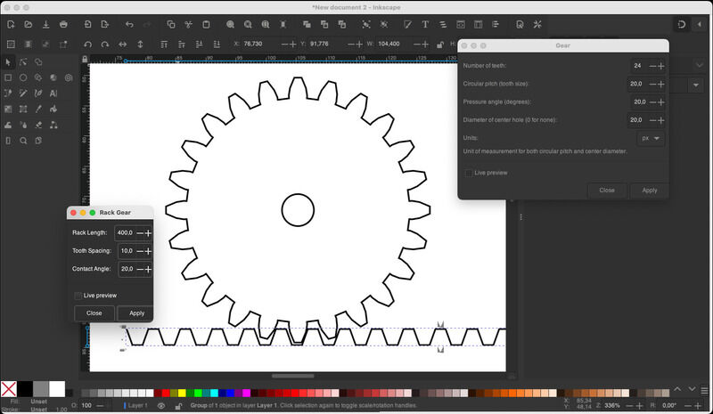
gear and rack from plugin (not much to edit)
The resulting inkscape design files (*.svg) can be found here
It would be awesome when Inkscape could provide some parametric settings too - the approaches found online range from using python-like-scripting or the approacht with cloning shapes which was also shown briefly in class. The challenge seems to me to develop a workflow where first all ‘cloned’ objects remain flexible, but after the boolean operation of converting them (substracting them) from a main shape into a path, the relations are gone and the only option is to step back in your history.
In inkscape standard parametric plugins for gears and racks are available, but adjustments and settings are limited. Extensions for the standard finger-joint boxes are there on the extensions page.
For now enough of 2D. The shortcut I often take for images on macos is to use keynote, which has exellent alpha-blending and shading tools etc. Especially for annotating pictures (quick lines, arrows etc. it is great).
3D exploration
As simple test of (each) of the bits of software I try a simple box (40x50x20, 2mm wall thickness) first, and then some additional modifications / changes - each for 30 minutes max.
Fusion360
Reminds me a lot about the earlier experiences with SolidWorks. A basic workflow is to start with a drawing, then extrude, draw on the newly created planes and continue building. There are (very) many ways to achieve the same results, but the ‘right’ way to define a compoent usually presents itself many, many steps in the design process later. As quick test I started the box with a drawing consisting of the outer line and inner line (so one reactangle and one with 2 mm offset).
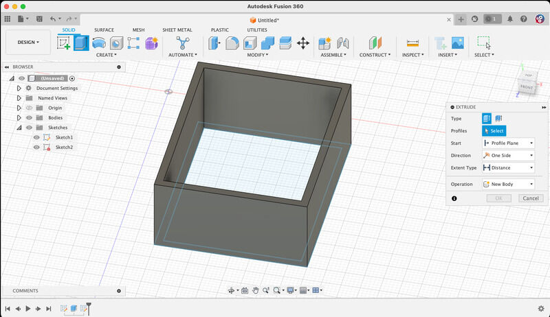
box started with wrong sketch.. one feature at a time please
Extrusion the drawing yields a hollow box (so no bottom). Drawing a new extrusion (new sketch on plane) apparently automaticlly selects the top plane- so my box ends upside down.
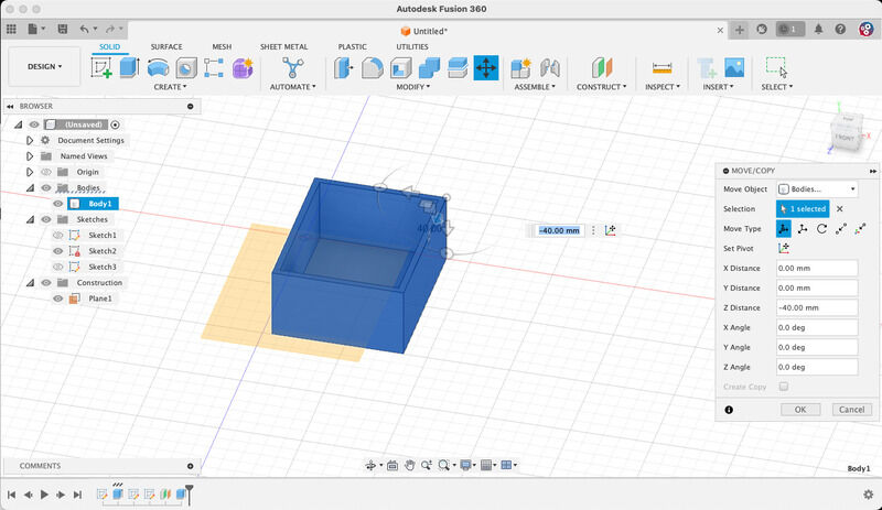
box started with wrong sketch.. one feature at a time please
It is however very easy to continue the work, make some holes, chamfer the edges, etc.
- shift-middle: rotate, middle mouse: translate. So you need a mouse. Trackpad or trackball need more attention…
- either draw a shape and type dimension immediatly or right-click -> sketch dimension (D)
- making holes from a sketch does not work well (better to use the ‘hole’ tool)
- chafering edges is easy: select, apply ratio, etc.
- rendering is also very straightforward, Not sure whether cloud-rendering gives practical(better) results. This is done by ‘applying materials’. Results are not photorealistic but quite ok:
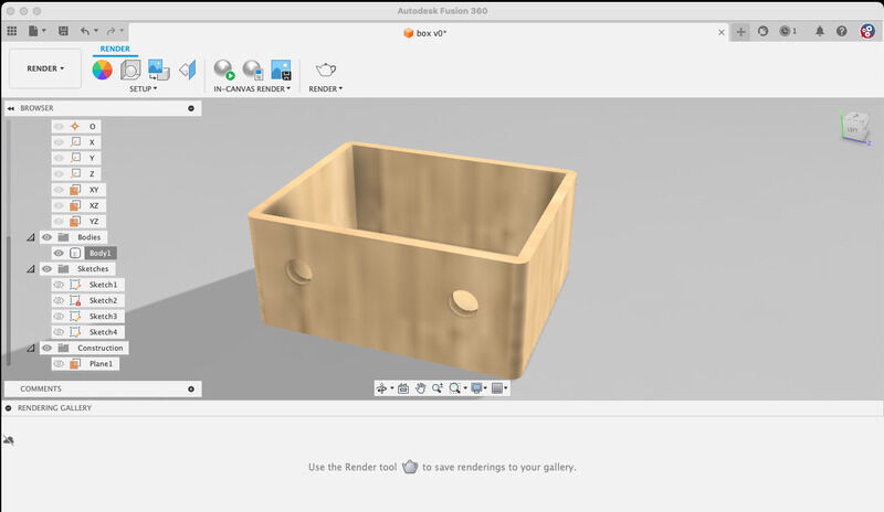
rendered box with material properties added
- export to *,stl requires cloud connection and throws up warnigns. Hmm. for me that would be a show-stopper in day-to-day use. Apparently a toggle ‘go online’ need to be set in the top bar. Now saving first locally (only possible when cloud connection is present? and in cloud for conversion to *.stl. Hmpf…)
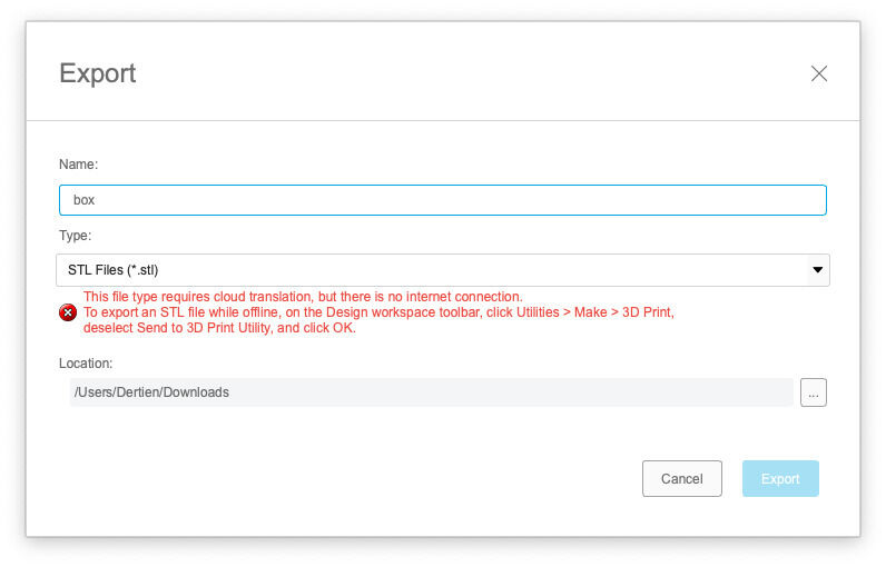
Fusion360 strongly depends on internet connectivityy
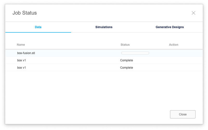
and even for simple *.stl render you have to have a working connection...
The fusion design file can be found here. *(Generated .stl is not listed for the sake of file-sizeing and triviality :)
FreeCAD
I had high hopes for FreeCAD (since it is enthusiastically shown in class by Neil, not so enthusiastically by Henk, but I suspect that’s mainly because of his week-3-over-constraint drawing trauma)
- orientation: left mouse rotate, right mouse translate, scroll wheel zoom (ok, clear)
- go to workbench ‘part design’, select plain (xy) select new drawing, draw square
- find horizontal and vertical constraint: give sizes (40, 50,). Annoying two different constraint bars (horizontal, vertical) Mouse positioning has an offset of several millimeter.
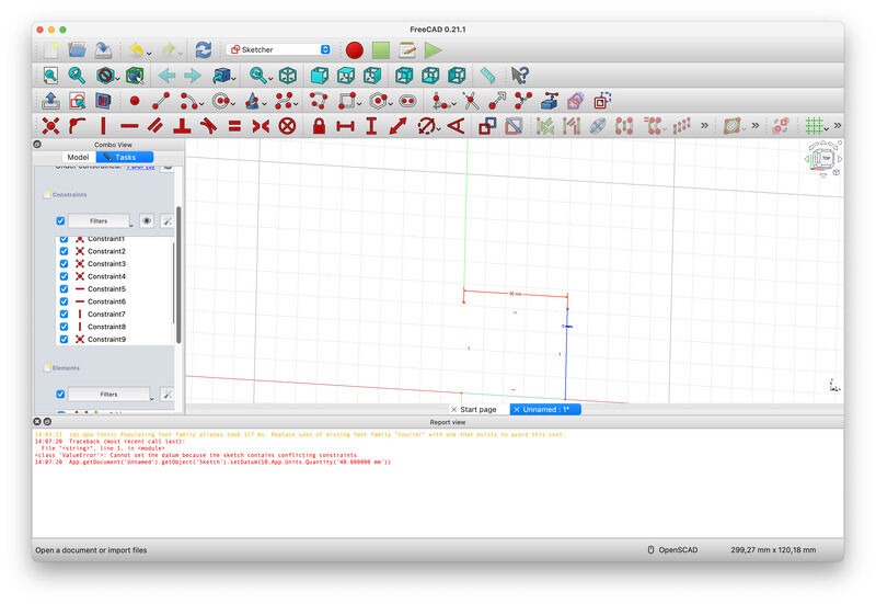
drawing a rectangle and finding the right constraint tools
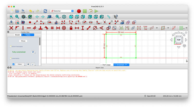
fully constraint (pfew)
- extrude = ‘pad’? -> ok try something else. Do undo. AARGH. sketch gone, -out of cheese error, redo from start-
- ah.. hitting escape, close etc -> your stuff is gone, but there is some sketches now left in the tree
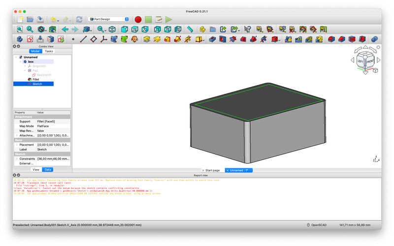
- the ‘additive box’ could be used to draw the box immediately. I choose pad
- select body, select sketch -> pad -> 20mm (ok)
- select edges (hold cmd instead of shift) - fillet (for round edges)
drawing a rectangle and finding the right constraint tools
fully constraint (pfew)
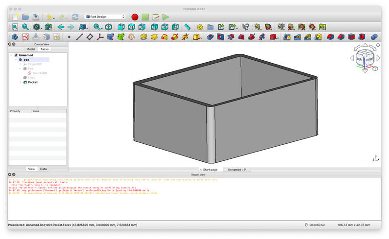
- constrain the inner shape (fill in point-to-point of sqrt(4) and line-point distance of 2 and we’re fully constraint once more)
- exit sketch, go to pocket, select sketch, edit depth
- next go to part workbench, (texture mapping becomes available) find wood (bamboo) sample picture online and map (at least temporarily )
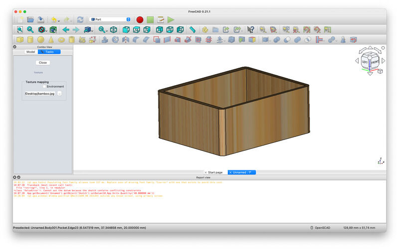
a quick material visualisation
- export is standard to *.stl
- free (no cloud :)
The design file (*.FCStd) can be found here.
In hindsight not so bad as expected, even without checking out tutorial movies… The sketching (and setting dimensions and constraints well - would be something to get used to.)
Rhino and Grasshopper
- in perspective plane: right mouse rotate, shift right mouse translate, scroll wheel zoom
- drawing a box is easy. Scaling a box? not so easy. read this forum post so perhaps go for grashopper once more
- give op on rhino directly and use grasshopper, as shown in the thursday class tutorial
- start up grasshopper
- select the rect block (double-click for search)
- select a rectangle (2pt) as input. double click on the plane and search() does the trick
- remove a connection: either replace or ctrl-select
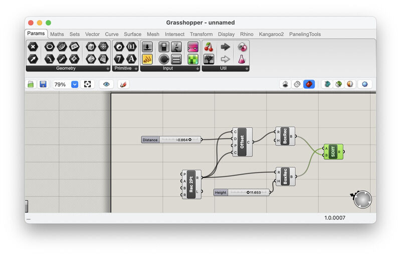
grasshopper attempt at box drawing with offset..
- add a substract-solid function, add a second rectangle with a curve-offset of the first one
- no idea how to ‘render’ the shapes (they are visible on the Rhino plane, but clearly not ‘processed’ or complete. For time-sake I stop here)
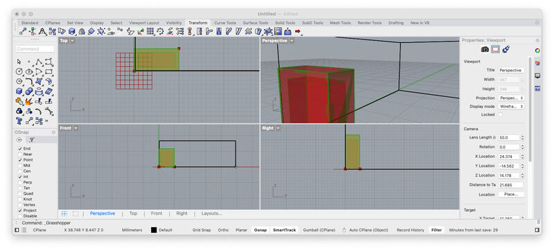
the resulting parametric shapes in rhino
Blender
I have been using Blender before some odd years ago, and compared with then - and with something like OpenSCAD it feels quite bloathed and overwhelming and powerful. During class we quickly explored the basics:
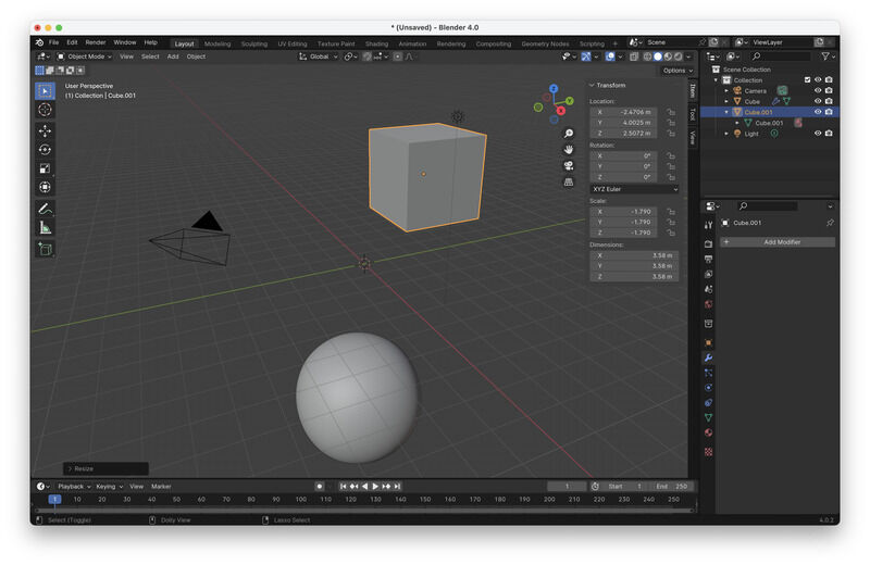
putting in objects
extruding faces using 'grab' (g)
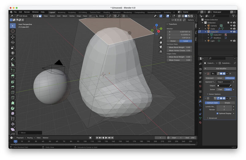
- blender: patterns -> height conversion -> French: relief!
- blender: subdivision surface (smoothing -> computationally intensive, last step)
- blender: maps (roughness, displacement, metalised, .. etc..)
- blender: tutorial
- tab: switch edit / object mode
- object mode: select -> g for grab, x,z,y for fixing translational axis
- modifier-> subdivision -> tab for switching between object and edit mode..
- e: extrude, g: grab, r: rotate: s:scale
- little triangle in right upper corner: translation, scale, rotate numericals
OpenSCAD
See the tutorial I wrote for this class specifically. For simple designs OpenSCAD can keep up, however, for more design complexity, organig shapes and assemblies you are not very well supported (as in, mostly left to your own coding hygene). Still, for the final project I have in mind it might be good enough.
Final project design
Since the start is mainly technical, for now I continue with OpenSCAD to design the objects. Later I can try how to insert them into FreeCAD (using the OpenSCAD workbench). After the (functional) design is ready I will try to import and render in Blender. The freecad wiki also lists blender as the best rendering option.
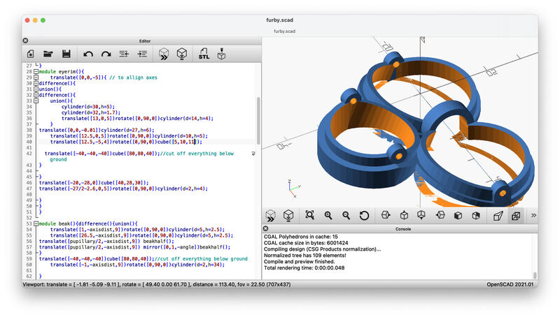
furby face design
Using callipers I went over the main parts that make up a furby face:
- eyes, for now without pupil, iris and cornea. (Note the cornea does not bulge)
- eyelids
- base frame (which has a offset, unlinke the ‘simple’ thingiverse version)
- beak (2 halves)
- tongue
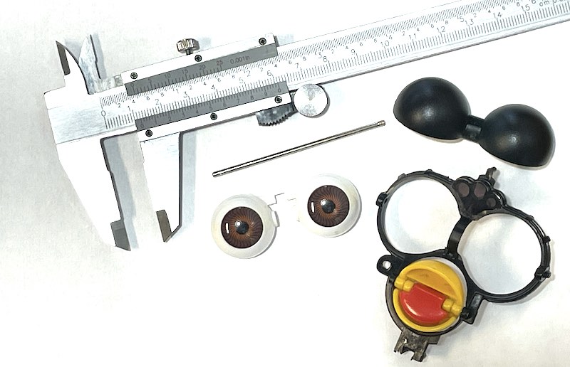
dissassembled face and main tool for the job
Everything hinges mechanically on two 2mm steel shafts. Later on I will include a tendon-drive mechanism to operate beak and eyelids and eyes. (It might be interesting to use the official mechanism as starting point but convert it to a 2dof eye (so eyes can also look left-right. now, THAT would be creepy :)
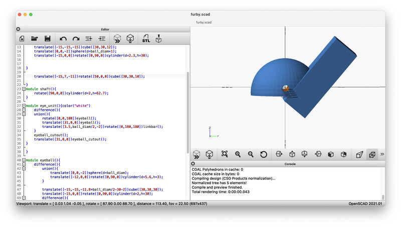
drawing the cut-off shape to check
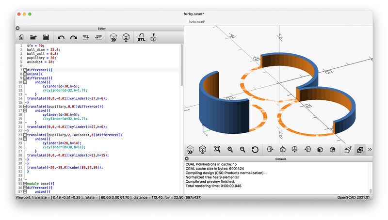
first hour of work.. all in the eye of the beholder
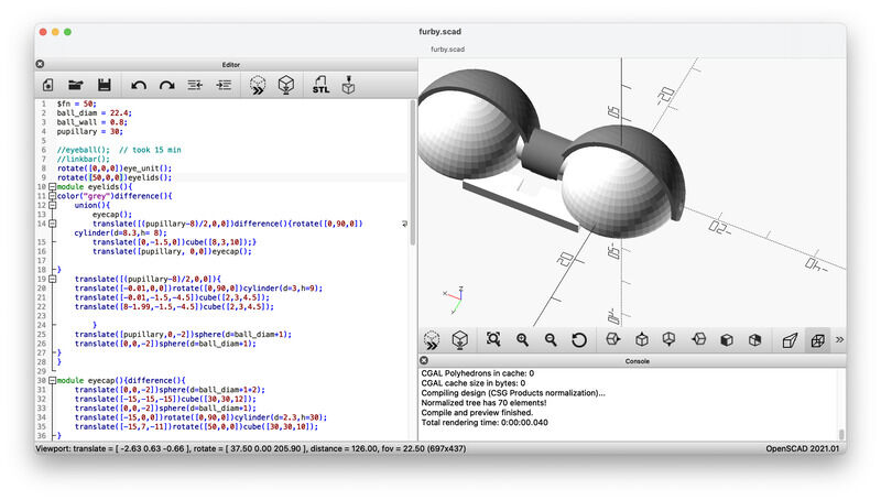
The eyes need to be re-worked based on the manufacturing process. Wall thickness for the cap and eyeball is important, as well as the gap in between. For that reason those have been put as parameters at the top of the code, I expect to have to work on them (or do a few iterations) before printing. Next up is the frame. The beak has quite an off-set forward compared to the eyes. This was ommitted in the earlier referenced thingiverse model. It -is- quite a challenge to find a way. After experimenting with a hull shape (think ’loft’) I picked it up with mirroring and tilting. A global parameter (angle) is used to allign the beak section and eyes section.
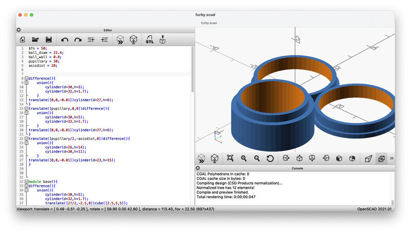
the basic shapes for the face-plate
the bit that needs to slant
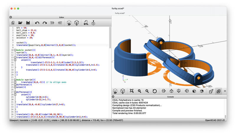
slanting the eye-rim section
tilting the beak section
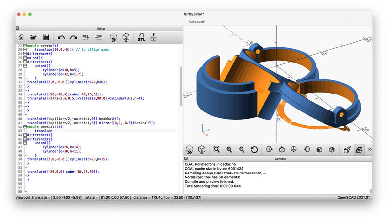
alligning beak and eyes using ``angle``
insert bridge between eye-rims
I did not fully parametrise the design (yet). The two main sizes in the design are the distance between the two shafts and the pupillary distance. However, not every parameter scales well with changing them (yet). First things first: next up are beak and tongue.
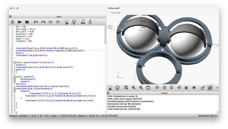
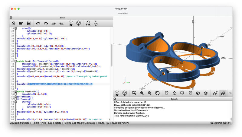
eyes and eyelids placed in the frame
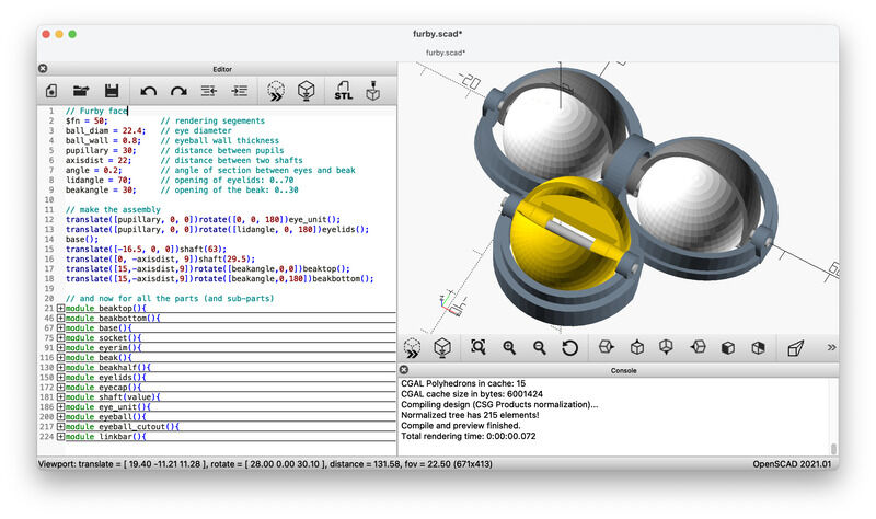
beak sections added
They eye(lid) and beak have a global parameter (beakangle and lidangle) which can be used to move them to a certain position. There are no limits programmed in (yet) but later they might be used for animation.
Overall the modelling took more than 6 hours straight. I’m not sure I could do better using a different tool, since the elementary task (measuring, finding the shape, position it correctly) do not change. Compared to earlier projects I tried to make use of symmetry and mirroring as much as possible.
Next up: integrate the furby face with a synth-module plate and add user interface elements
modular faceplate (pun intended)
Next up is the modular plate. The sizes for synth modules (eurorack) are parametric and descibed for example on the following page / picture.
The plate will have to fit a standard modular synthesiser rack. the following drawing specification is avialable for Doepfer’s modules:
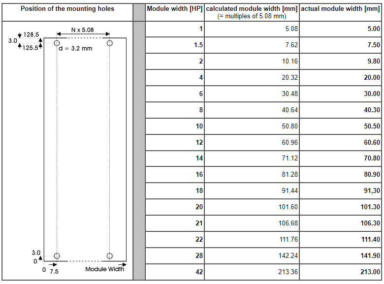
Doepfer's modular dimensions
the Eurorack modular plate is straightforward to catch in OpenSCAD:
module modularplate(units,thickness){
    a = 7.5;
    b = 3.0;
    h = 128.5;
    hole = 2.5;
    color("silver")
    difference(){
        cube([2*a+units*5.08,h,thickness]);
        translate([a,b,-0.01])cylinder(d=hole,h=thickness+0.5);
        translate([a,h-b,-0.01])cylinder(d=hole,h=thickness+0.5);
        translate([a+units*5.08,b,-0.01])cylinder(d=hole,h=thickness+0.5);
        translate([a+units*5.08,h-b,-0.01])cylinder(d=hole,h=thickness+0.5);
    }
}
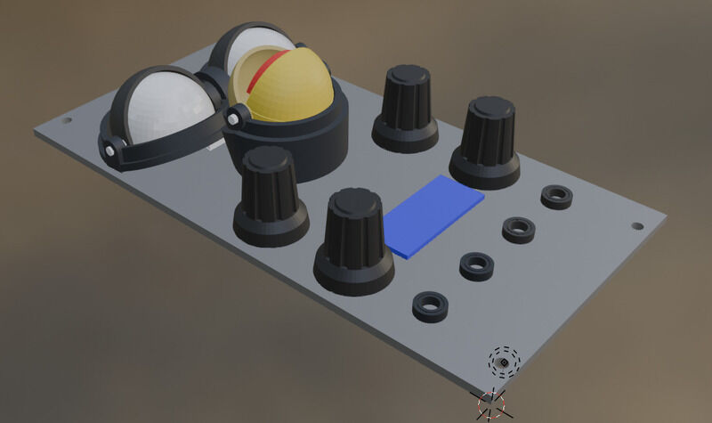
The furby module is placed at the top, with the controls and connections planned at the bottom.
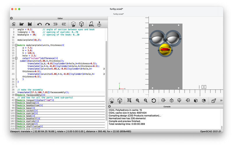
eyes and eyelids placed in the frame
The interface elements are chosen relatively simple, although, for reference the knobs need to be modelled very precisely. For the display (SSD1306 OLED) a simple rectangle can suffice for now, for the jack-sockets cylinders at the right sizes and colors.
The knobs (especially the knurling) need a bit more work to be realistic:
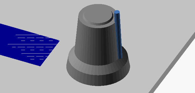
bare knob
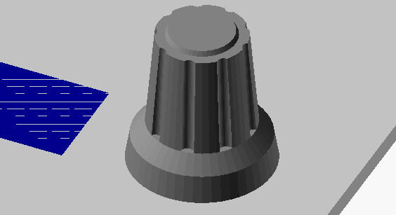
knob with the rims
With the design of the knob I used a for(i=[0:40:360]) instruction (which I hitherto did not use much) but is actually quite ok to use, as long as you choose your coordinate frames wisely. (so don’t be afraid to use multiple rotation vectors and don’t try to cram them all into one. Remember, we do vectors, not quaternions or rotation matrices). Also a nice touch is to pass a color as argument. Apparently OpenSCAD has no definition of variables and it does not matter whether to pass a string, name, value or something else. Passing the color to the top-bit of a knob is a nice touch :)
With that the interface elements can all be placed. For now I expect to use 4 rotary elements (potentiometer / encoder): a modulation input, A- and B- setpoint for the loop / grain and a file-selector. The synth needs three inputs (gate, cv, modulation - or gate, cv, trigger) and one output.
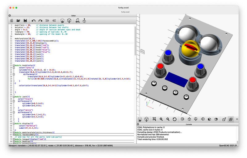
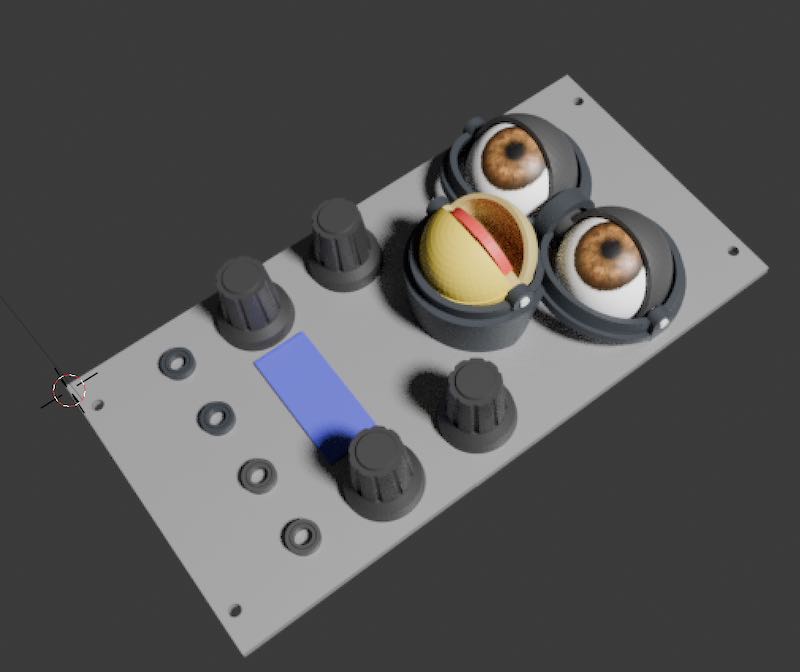
Full design with baseplate, furbyface, and interface elements
The final design file is this one: furby.scad (save as -> open with openscad)
animation using OpenSCAD
For me the animation function of OpenSCAD is new, and both again simplistic and powerful (and fun :). With $t in your code as time step, you can animate in OpenSCAD (did not know that). A parameter $t will depend on the time and scale between 0 an 1 in a number of steps (defined by steps) and the number of frames per second. You see the time-step value changing as soon as you entered two values. The render(preview) cycles also automaticlly start after entering the values. When you want to store one set (one full time-sweep of 0..1) you have to check the ‘dump output’ box. And that’s it..
The series of images can be converted to a *.mp4 clip using ffmpeg:
``ffmpeg -framerate 30 -pattern_type glob -i '*.png' -c:v libx264 -pix_fmt yuv420p out.mp4``
which got a bit longer after a height not divisable by 2 error that ffmpeg threw, solved by this post on stackoverflow
``ffmpeg -framerate 30 -pattern_type glob -i '*.png' -c:v libx264 -pix_fmt yuv420p -vf pad="width=ceil(iw/2)*2:height=ceil(ih/2)*2" out.mp4``
Hugo needed the following shortcode to embed a video (not standard with the template.) It uses a video player called ‘Clapper’ - (I’ll see how long it works. Not sure if I can host the clapper sources locally?)
In the code I replaced the angular position for the beak and eyelids with a offset + amplitude * sin($t*360) which works nice for now. More elaborate animations probably need a lookup-table or other parametrisation. For now you get the idea:
OpenSCAD animation of the Furby Synth module (171kb)
(That’s all, folks!)
render using Blender
So, I started with Blender a bit later than forseen - with as goal to make a better render of the module, give the furby eyes some actual eye-images, etc. I tried the following steps:
- import the full *.stl: no / go. Might be useful as reference, but the best start is to import separate *.stl files
- good point: the reference location from OpenSCAD gets transferred, so you don’t need to place the components (!) (yay)
- I take a sneek-peek at vera’s steps, since she already succeeded in rendering with help of a very-experienced-in-blender-colleague… So, let’s go!
- upon import the *.stl’s look worped and unclear. the magic button is object -> shade auto smooth. Now they are sharp and unclayed once more
- *(so, at this point, I will update my openSCAD .stl export with all files, since it is very useful to have the correct positions of components already present)
- now: assigning materials
- mapping an image - does not work (nobody explains the node editor… ) - here is the missing link
- setting active camera and alligning to view
- mapping with the node editor
Importing everything from OpenSCAD into blender:
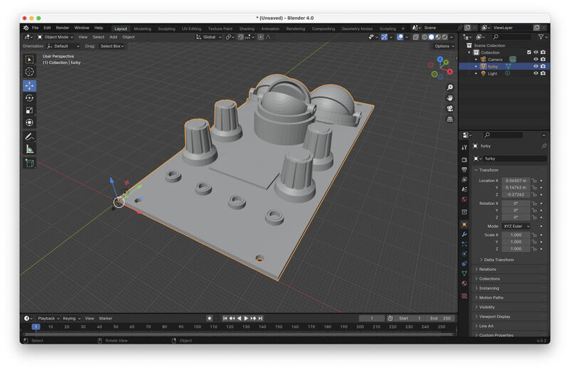
wrong OpenSCAD export, all modules in one *.stl
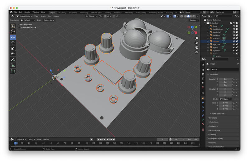
the separate stl's keep their location (yay!)
Next up: setting material properties and changing some positions
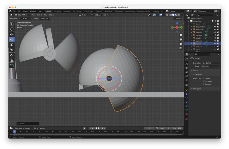
set the coordinate (cursor) for rotation so the eyelids can be closed abit
setting material properties. The white shene comes from the original full model still visible as reference
The size / scale (and position of camera and lights) are not matched to the design. Viewport renders seem to work but actual camera selection and rendering does not work yet
render view
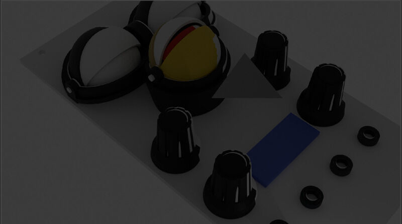
output of the render/shader menu. Something wrong with the lights...
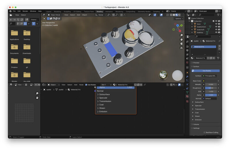
An other wish is to map the image of an iris such as this file to the eyeball. Instructions are a bit unclear at this point.
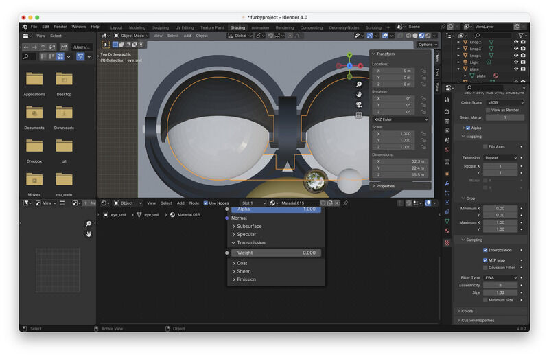
try to map an image using the right-side menu (fail)
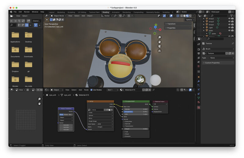
image mapping using the node editor
Todo
- camera setting - somehow the camera disappears and rendering renders void
- texture mapping: a small picture of an iris to the eyeball (should be possible) but all that happens is a color change
addendum week 3: done (!) - changed camera position (edit camera controls) to get the furby in view and tweeked the mapping of the iris-picture:
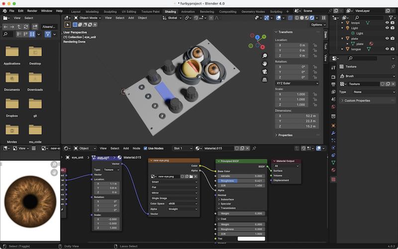
image mapping using the node editor
learning outcomes
The task for this week is to explore 2D and 3D design tools and design/render/animate the final project.
evaluation checklist
- Modelled experimental objects/part of a possible project in 2D and 3D software
- Shown how you did it with words/images/screenshots
- Included your original design files
*Note that for including the design files I made a selection only to include files smaller than 1 MB in size. This means that the full .stl (1.3 MB) and Blender files (5.6 MB) are not included, but the OpenSCAD script is everything you need :)
lessons learned, tips and tricks
- stay on the lookout for symmetry and other clever constraints
- choose your reference (and coordinate frame) wisely, especially rotation axis help
- animation is possible in OpenSCAD (yay!)
- make a tree just like Fusion360. Collapse modules for overview :)
- in VS-Code auto indent for c-style code: On Mac Shift + Option + F
left for todo
- adding buttons and UI elements: or in OpenSCAD, or in combination with KiCAD
- making material property-correct render in Blender
personal reflection
For robotic design projects during studies and internship(2004) I have been drawing with SolidWorks and Catia. Since I have transferred to mac (about 10 years ago) I have been struggling every now and then to get a dual-boot system and get SolidWorks installed again, however, it would never seem to work fluently. A first Blender tutorial (some 8 years ago) was nice, but the user interface (with three-button mouse) was something that required regular practice. I did not have the projects (or patience) to master these skills. So for quite some time I actually have done without a proper 3D CAD tool. The last projects have been the PIRATE pipe inspection robot (also largely designed by proper mechanical engineers) and the Dancing White Man.
I only got round to watch tutorials partially. I must say I lack the patience. THe approach to dive in (and google quick how-to’s when a problem arise) fit my style of working better. Comparing the experiences with tooling I think I am happy to stay with OpenSCAD as my main tool (and further hone and sharpen my skills and workflow). There is much to explore (libraries) which can be used to improve my skill set. Next up FreeCAD did seem like a useful addition, especially for features like chamfered edges etc, which are (be honest) a pain, or simply not possible in OpenSCAD. Fusion360 was allright. You need to build up routine (again) so you make sure to build-in the right constraints in your drawing.
Blender still stays on my wish-list to expand and explore further, since the tasks and tools seem very complementary to what I am able to produce in OpenSCAD, however, for size-accurate, precise mechanical drawing (such as my chosen project) it still might not be the best tool.