introduction
The group assignment of this week is to review the safety data sheets for each of your molding and casting material, make and compare test casts with each of them, and finally compare printing vs milling molds. As individual assignment the goal is to design a mold around the process you’ll be using, produce it with a smooth surface finish, and use it to cast parts.
As individual project I am going to work on eyes for my animatronics projects in general - and for my final project furby synth specifically…
in the eye of the beholder..
group assignment
After a short lecture and demo by Michelle, sharing with us information from Materiom, safety issues and potential benefits of biomaterials (and her fascinating voluminous work for the academy on this topic). You can have a one-way, two way or three way (or more) mold process:
- one way: just cast, clay, sculpt
- two way: make a mold, cast something from that mold
- three way: make an object, cast the mold, cast objects from that mold.
A mold can be just one part, two part or multipart, with two and multipart molds typically creating some flashing (a seam) along the edges where mold parts meet. For two and multipart molds you have to take care of the entry holes and air vents for the material, especially when you try to do pressurised (injection) molding,
for the group assignment we decide to create some samples with the available materials, work through their safety sheets and simply try some test casts. Vera and Joany go for a bio-material recipe, Joe, Leo and I work through the available smooth-on materials.
safety sheet
We decide to work through the safety sheets of some of the materials present. We decide on a number of safety aspects and material properties that seem relevant and put them collectively in a list / table. (I added materials I had available in my (home)lab later)
| properties | mold star 16 casting material | epoxy glue (HEMA) | ecoflex 00-50 | smooth on pmc 121/30 dry | branda CE-SENSE 101 epoxy |
|---|---|---|---|---|---|
| safety | |||||
| room conditiions / environment | properly ventilated area, room size, room temperature | room conditions | room conditions | room conditions | room conditions |
| ppe | safety glasses, long sleeves, vinyl gloves (not latex), eye bath, safety shower | gloves | vinyl gloves, safety glassed, long sleeves | safty glasses, long sleeves, rubber gloves | safety glasses, gloves |
| exothermic / endothermic | no data available | no data available | no data available | no data available | exothermic |
| toxicity | no data available (GHS Compliant) | skin / eye irritation | no data available | harmful | harmful |
| environmental harm | no data available | yes | no data available | yes | harmful |
| special/other | avoid contact with eyes | – | avoid contact with eyes | ||
| material properties | |||||
| shelf life, | no data availale | no data available | no data available | short | no data available |
| pot time | 6 min | 5 min | 18 min | 30 min | 50 min |
| curing time | 30 min | 2 hr | 3 hr | 16 hr | 24 hr |
| ratio/ mixing | 1:1 volume and by weight | 1:1 volume | 1:1 volume or weight | 1:1 pbv | 1:2 |
| viscosity | 12500 cps | – | 8000 cps | 1800 cps | – |
| shore / hardness | 16A | – | 50A | 30A | – |
| shrinking | <0.001 inch per inch | – | <0.001 inch/inch | neglegible | – |
| special/other | high temp resistance. sets quicker under warmer conditions. | – | – | – | – |
v-carve for milling
Next up the v-carve tool available at Waag is explained regarding required settings for mold making. The following steps are demonstrated:
- set job size 90 x 140 (mm)
- z zero on block (don’t forget what you do. wonky block - mill away or flatten top is an option)
- import model (3d file, like stl or obj)
- check orientation and center
- set zero plane
- material setup -> set model posiont in material
- go to 3D toolpagh -> rough machining toolpath / finishing
- machining limit boundary
- rough: 3mm end mill, 3 mm pass depth, stepover 1.8mm (60%) 9000 spindle, 50 mm mm/sec feedrate, 15 mm/sec plunge rate
- machining allowance. 0.5 roughing ..
- raster y (or raster x) -> check what is easiest on the machine (avoid moving the gantry)
- 3d roughing instead of planar rought (x/y raster) strategy: smoother but not so quick
- finish: 10% steopver, 9000 spindle, feedrate and plunge rate 50 mm/sec and 15 mm/sec (no pass depth, path is nonplanar)
- tool changes -> it’s a choice… Not having to zero again when chaninging a bit has its merits.
- keep off / don’t use dust extraction so you can scoop up the wax end re-melt.
material scrap try out
As group assignment we tried a large number of scraps and material samples, most from smooth-on (exept the jesmonite)
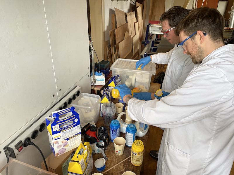
Leo and Joe at work
-
smooth-cast 305 liquid plastic (2018) - cast in cup and in PLA shape, 28g + 28g. Result: lot of moisture, sticking firmly to the cup (mold). Stays realy poorable liquid.
-
mold-star 30, try in cup with PLA object, 30g+30g
-
jesmonite AC100 starter kit: 25g powder + 15g liquid + colour
-
dragon skin (joe) 25 g + 25 g ()
-
oomoo 25 (leo) 30+30 g, brand new. perhaps not stirred well enough. gunky..
-
bioplastic (glycerine + gelatine) (vera and joany) - sticky (flexible)
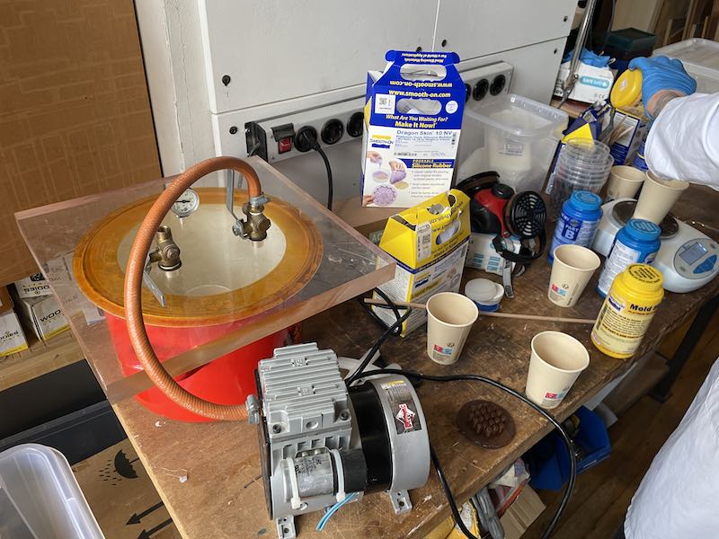
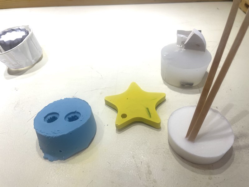
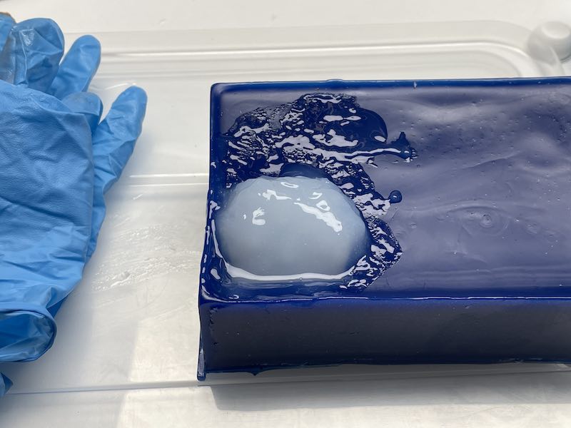
For the mod-star I use the vaccuumchamber for 10 minutes to get air bubbles out.
Caption for Image
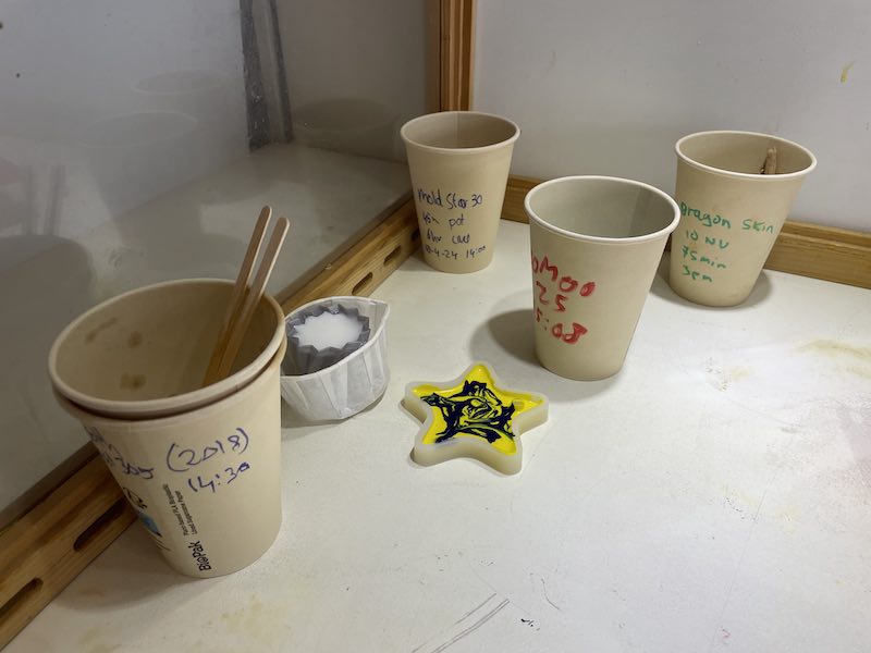
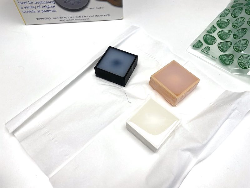
Samples curing in cups (jesmonite in tiny star)
The selection of samples ready after 1 hour of setting time
The bioplastics are very nice and sticky..
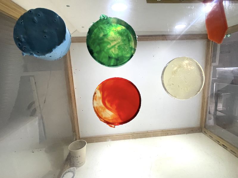
Samples sticking to the fume hood window
comparing milled mold and casted mold
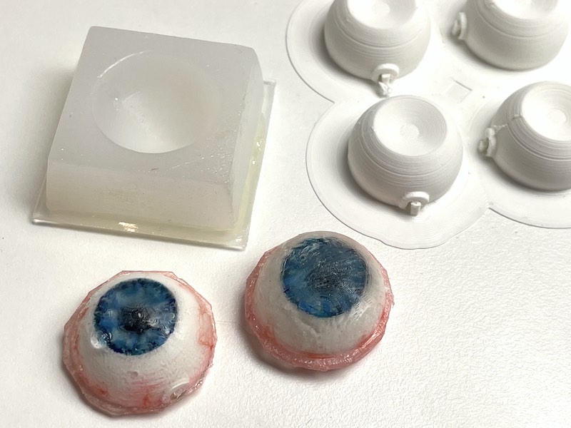
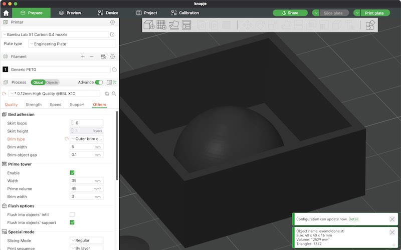
For the individual assignment I designed a quick one-part 3-way mold for a furby eye. The idea is that a printed ABS (or differently cased eye out of white plastic material) will be inserted in the mold with clear epoxy, so the epoxy will form the cornea (with a nicely painted deep iris). The following OpenSCAD script is used to create the mold.
difference(){
    cube([40,40,16]);
    translate([20,20,2])rotate([0,0,45])cylinder(d1=sqrt(2)*32,d2=sqrt(2)*36,h=14.01,$fn=4);//
}
difference(){
    translate([20,20,2])sphere(d = ball_diam+0.4);
    translate([0,0,-20])cube([40,40,20]);
}
translate([20,20,0])hull(){cylinder(d=14,h=11.0);translate([0,0,7.2])sphere(d=14);}
I try to use this design for a printed version - since I don’t have a resin printer in my lab, we have a go at the resin printer @waag.
individual assignment
This would be nice for furby eyes? transparent clear acrylic, with paint … see the diy animatronic eyes youtube vid as starter? Perhaps make them scalable (multiple sizes)
or what about using the furby face internals for some proper facial reconstruction and cast the normal face (pink silicone)
For making realistic animatronic eyes there are many tutorials online. Mostly they use polymer clay cast in a thin layer of epoxy this tutorial or this
The best video (as in, most instructive and yielding results closest to what I normally use / buy) is this
plan: In order to practice my skills in making realistic eyes, I’ll try to get the process underway with small, hyper realistic furby eyes for my final project :)
The video by will cogley uses the following steps:
- 3d printed ball shape, primed and polished used as master
- silicone mold of the 3D printed shape
- 3d printed abs inner shape, sanded and polished
- hand painted iris and pupil, airbrushed eye-red
- use cotton threads with superglue for veins
- cast in small amount of clear epoxy into iris (bubble-free)
- epoxy in silicone mold, put in eyeball, set to dry
I use OpenSCAD to create an inner shape (based on the eyeball design in the furby face mechanism of week02) and an outside mold including a cornea bulge (to make it more interesting than just a half-sphere). For the iner shape I use a conical cutout as iris, also to give the eye more depth (hopefully when adding a nice transparent bulging lens on top). I use a tapered shape as square insert. (the ‘hacky’ way to do this is by using a low-poly cone. there are no trapezioids as standard shape in OpenSCAD.)
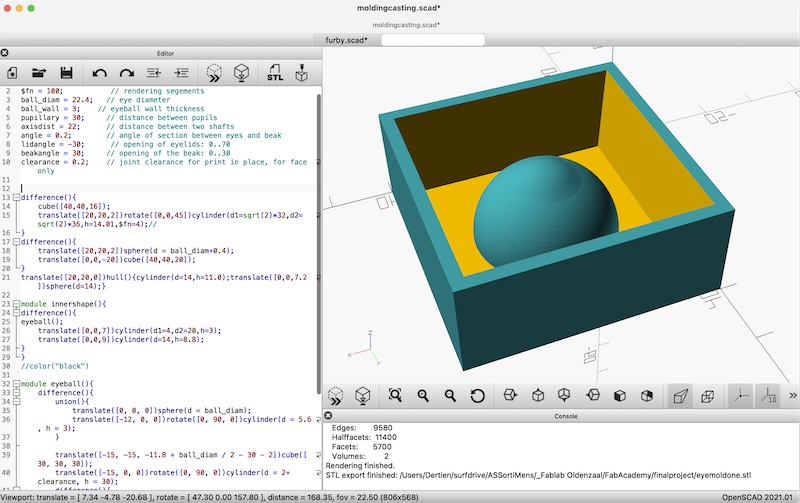
model of eyebal and mold in OpenSCAD
The design files can be found here:
toolpath
Good cam software is the thing. Based on a quick internet search I arrive at meshcam which seems to do what we need today. 250$ for a lifetime license is also manageable for our lab and use, so I decide to give it a go. Try out.. have to set tools. Manual: -> set machine region to define the pocket to clear. The program is nicely consise and it looks like most important settings can be accessed.
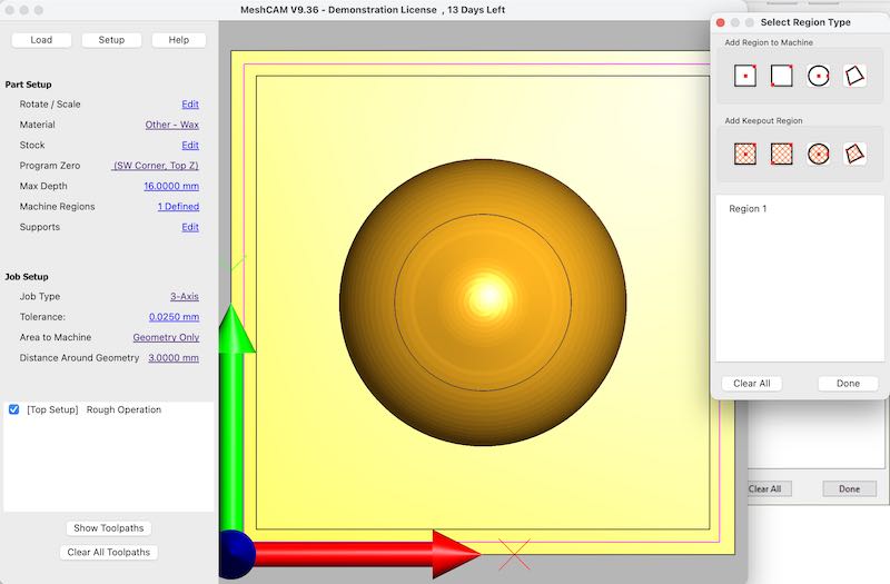
setting the region in meshcam
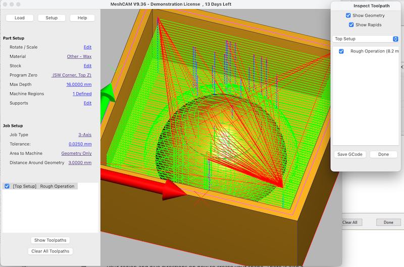
rough pattern in meshcam
Mods can also generate 3D toolpaths. However, there is no option to set the region, and at the first go I cannot find an easy setting for roughing or finishing. The same STL with standard 3.125 end mill gives a 63k gcode file in meshcam and a 7 MB file in mods (also causing the browser to crash)
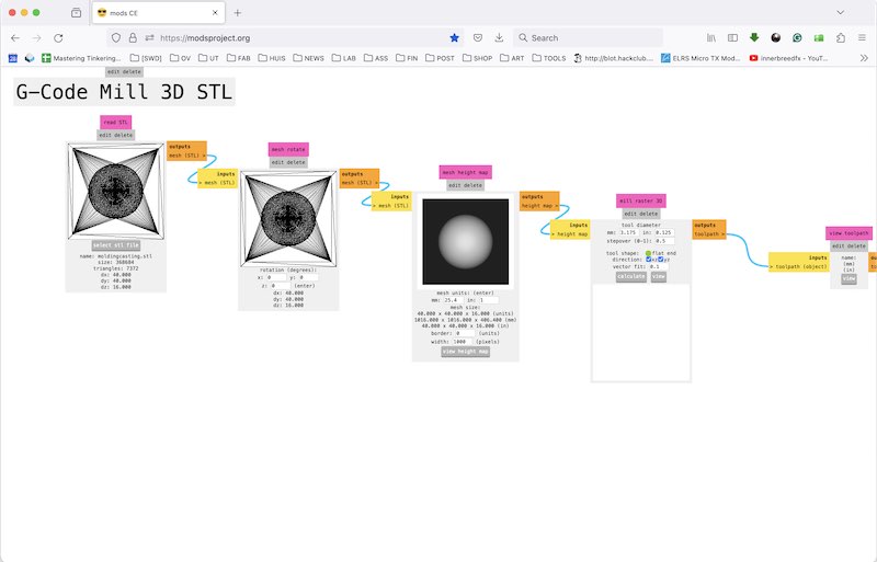
using mods for 3D toolpath
It takes some tries with mods’ settings to create paths that could be useful. Especially settings for units (mm/inch) are easily overlooked and can cause very detailed meshing (and browser crash). When the size settings are correct the paths seems pretty useful. I generate a rough cut and final cut and load them in ugs for visualisation:
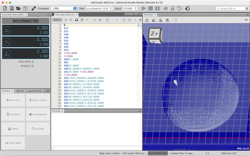
first try of toolpath in mods. Incorrect sizes

(wrong)roughing path
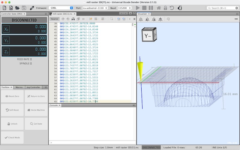
correct rough path
correct finishing paht
Eventually I decide to go for meshcam and process the files for milling. In MeshCAM V9.36 I set the material at WAX and a ‘generic 3018’ as machine. The job time is standard 3 axis with a tolerance of 0.025 mm. Sizes are taken from the job, so 40x40 mm, 16 mm max depth.
For the roughing I use:
- end mill 3.125
- feedrate 2000
- plunge 1000
- RPM 5000 (but I doubt whether the 2030 has a speed control for the spindle)
- stepover 50%
- stepdown (2.5)
For the finishing I use:
- end mill 3.125
- feedrate 800
- plunge 400
- RPM 3500 (but I doubt whether the 2030 has a speed control for the spindle)
- stepover 15%
- stepdown (0.5)
milling wax
I use the 3020 in my home lab with UGS as gcode sender.
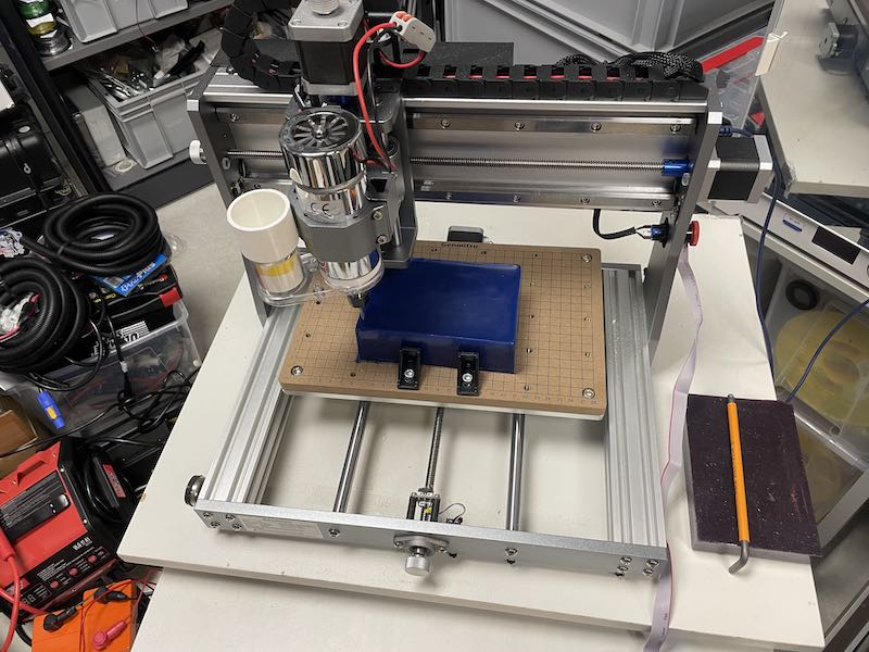
Clamping in a block of milling wax

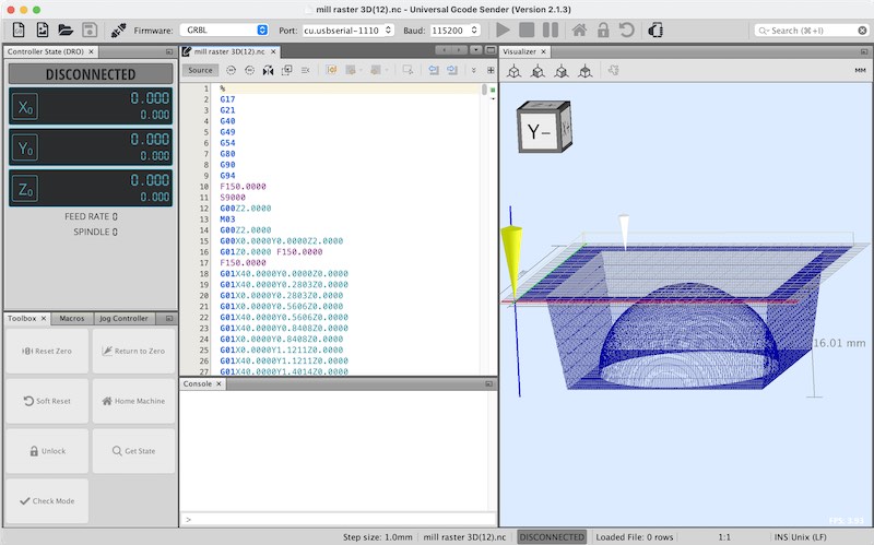
toolpath loaded in UGS
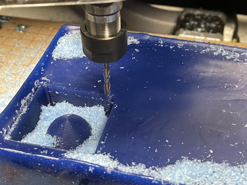
3020 in action
rough mill
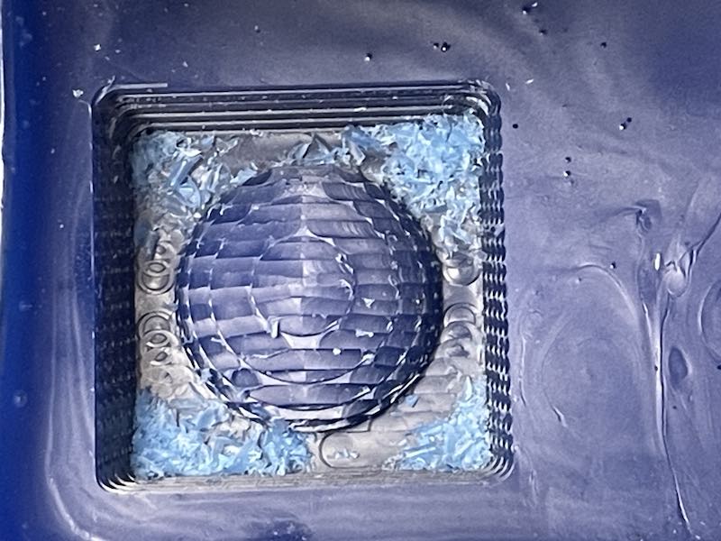
Finished rough path
Finished mold
resin print
The resin print has been made on Waag’s elegoo machine. Again Henk demonstrates how to use chitubox. The main thing is to make sure that there will be no islands, every bit printed has to be mechanically linked to the buildplate (much like a standard FDM print but then upside-down).
Layer simulation in chitubox
The resin print has been paused halfway by Michelle to check whether it was actually printing. In hindsight I don’t know whether that might have lead to slight decolouration and deformation around that time of print. After printing we clean the print (5 minutes in ethanol, stirring) and post-cure it (5 minutes UV). Cleaning up everything.
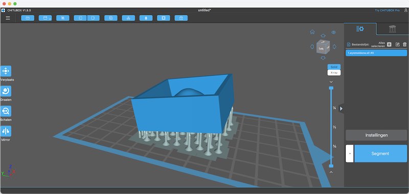
Chitubox mold model
printing ABS
It would be nice to try to print with ABS - both for the mold shape and the eye-white that is going to be casted in. ABS can be smoothened by Acetone vapour, so it might save some steps in preparint the original (sanding, using primer). I have two big spools of ABS in 3mm from the dawn of time. One is by ReprapSource.com, the other is of unknown origin. Since the material is still quite flexible (after 15 years) I decide to give it a go in my Ultimaker 2+. I clean the buildplate, use standard ABS settings, slice the model with high precision (0.06 mm) and let it start a 10 hour print job (4 eyeballs and 1 mold)
Next morning the printhead is attacked by a severe ‘blob of death’. One part (on the nozzle) can be removed quite easily, the other part requires me to completely dissassemble the head. Next up I try a few more times, even with a raft (last time I did that was on a MakerBot Thing-O-Matic), but mostly the first layers fail and refuse to stick to the bed. Also a nice layer of UHU glue-stick-glue (the standard remedy, I have not had to do this for years) does not help. Eventually I give up on this ABS and spend the rest of the afternoon calibrating, replacing the nozzle and bed levelling for my machine to be happy once more with standard PLA. (so, once more, no more messing around with ABS or other ‘interesting’ materials. My Ultimaker2+ is happy with PLA. Perhaps I need to be happy with that too)
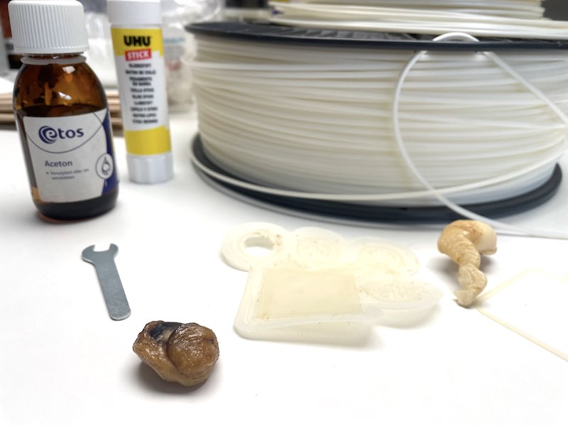
ABS blob of death, gluestick, smelly air and bad memories....
So. ABS. Brings back memories to the first reprap I build, and then the Makerbot Thing-O-Matic. The wonderful smell of ABS in the office (which was of course completely harmless as everyone assured us). Hassle with double-sided tape, single-sided tape, heated beds (what novelty!), glue sticks and whatnot. Perhaps that is a chapter best closed for now.
Instead I print a mold on the Ultimaker and on a Bambu, respectively in PLA and PETG.
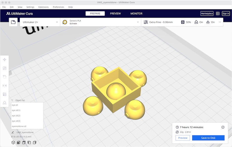
PLA on the ultimaker (including eye-insert)
PETG mold on the bambu
painting the eyebals
Similar to the referred youtube video, I take the white PLA inner eye-bals and use acrylic paint to make them more eye-like. In my workshop I have a small airbrush, vapour extractor - and a small selection of acrylic paints. In the end I use
- the airbrush and some bright red paint to do the back rim of the eyeball
- the airbrush and some black paint to give the irises a back coat
- some blue, green and white acrylic paint and a small brush to paint the iris
- a drop of black to once more black out the pupil
- hobby knife to fray some red cotton wire and glue this on the lower part of the eyeball as veins, using superglue (gel)

using airbrush for red rim
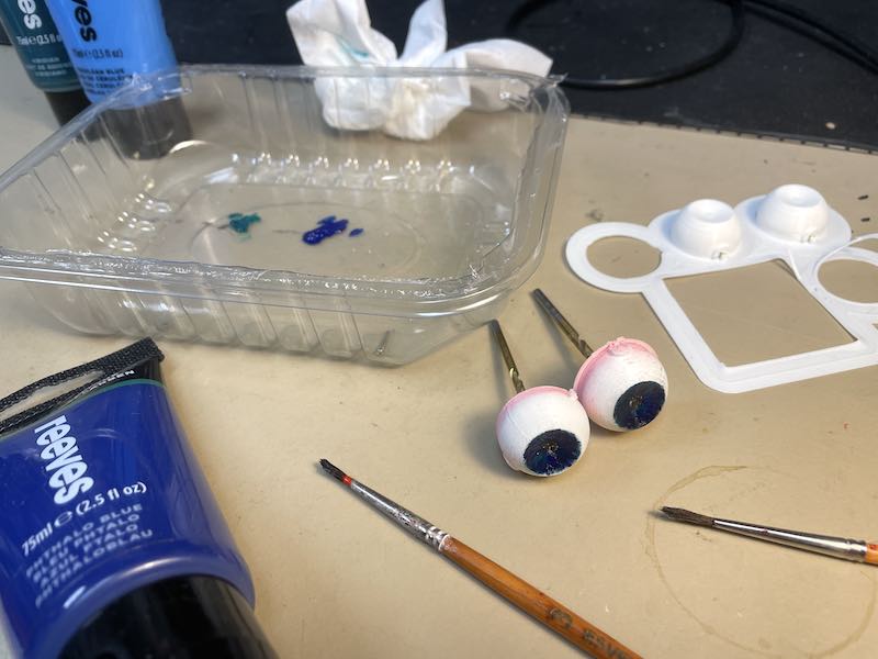
using green and blue acrylic paint
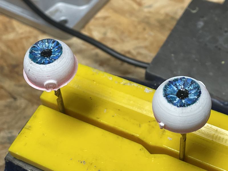
eyes ready
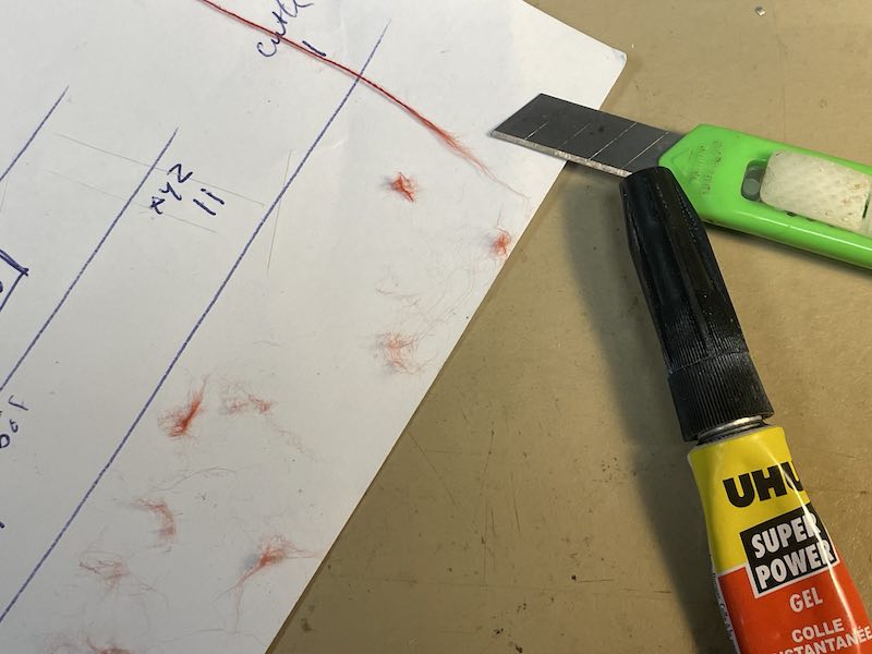
frayed cotton thread and superglue for red veins
casting the ecoflex mold
For the first series of molds I would like to use Smooth-On PMC-121 polyurethane. The bottle however completely solidified (so much for shelf live). Both the wet and dry version are not useful anymore. (I now remember that they probably come from a donation by the MIT group visiting Amsterdam during Fab6 in 2010. They came from afar and brought us gifts: 110V power supplies and molding wax. So it took me apparently 14 years to catch up with the subject matter. For me personally the lesson is sinking in. What cannot be said about the PMC121 anymore. Anyway, what goes around comes around… :P)
PCM-121. long overdue
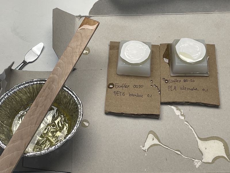
Next up I try to work with a scrap bit of Smooth-On Ecoflex 00-50. I have been using this material for many ‘interactive inflatables’ a.o. with Sensoree founder Kristin Neidlinger. Our collaborative project was even featured in the 50th edition of make magazine. Part of the ecoflex is fighting me at every step. It hides in the bottle and refuses to come out. I manage to stir up a batch and cast it out in the waiting molds: PLA (Ultimaker), PETG (Bamboo), Resin (Elegoo). The wax mold gets the last bit (which is already setting and now quite lumpy). Before casting I have spraid the molds a bit with baking-spray as release agent. Not sure the resin print likes it.
I use the compressor to remove bubbles. Not using air pressure or vacuum but just vibration. Seems to work quite well:

Using the compressor for bubble removal
popping...
the 3d printed molds in PETG, Resin and PLA (also eye-inserts)
The ecoflex is poored in. I use a bit of water in the mold (and measuring cylinder) to decide the amount of Ecoflex needed. The 00-50 I cast in wax is already pretty much set…

Very Archimedian: using water displacement to measure volume
ecoflex in the 3d printed molds
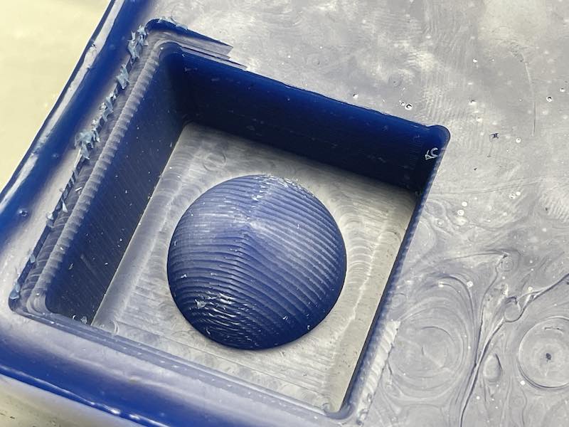
wax cast
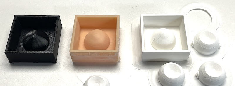
The molds that come out are quite different. The wax mold is by far the worst, mixing was not ok so large parts have not cured and the mold does not come out in one go. The other three are quite ok, bar a few bubbles…

4 molds in wax, resin, PETG and PLA
casting the flexcoat mold
After the ecoflex has been cured and removed I try using FlexCoat silicone rubber. It comes with a small bottle of hardener with a mixing percentage of 5%. I mix up 200 ml of silicone and add 10ml of hardener using a syringe. The material has a pot life of 50 minutes. The silicone is already quite viscous when it comes out of the can. I poor the mix into the four molds: (PLA, PETG, Resin and Wax). However, after 3 days the material still does not set and consistency does not change. I’m afraid that either I have the mixing ratio wrong (possible) or that the material is long past its shelf life (most likely). I have to give up and start the cleaning.
casting epoxy resin eyes
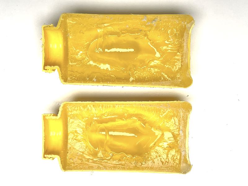
The first series of eyes (unpainted testers) are cast using CE101 epoxy and hardener. I mix both components (see table) in a 1:2 ratio. It is supposed to be (crystal)clear, but the hardener has some discoloration. I don’t know whether it will go away so I try using unpainted eyebals.
First eyes in PLA and PETG mold
Results. Not very transparent, yellow colour
Next up I use 2-component epoxy glue from a hardware store. I use a 2*12mm syringe, eventually using 4ml of compound per cast. Very material efficient in a way. I carefully stir (not scoop) the mixture and cast a bit in the mold. I also cast a drip in the hollow iris (so no air bubble will be captured) and subsequently dip them in quickly.
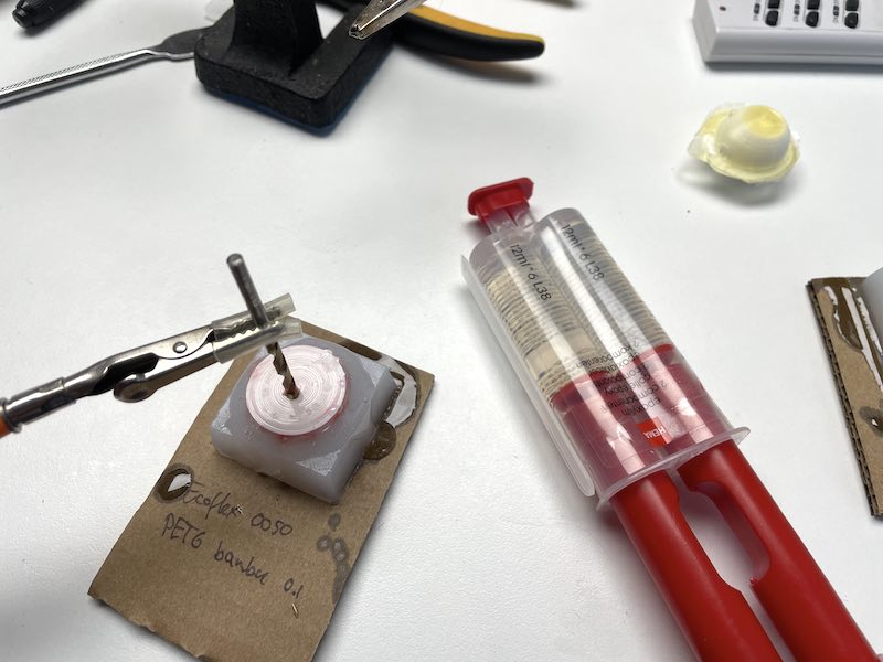
Epoxy glue as casting material
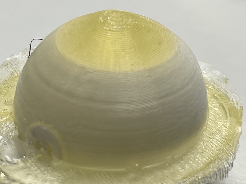
final result
The result is OK. The best cast is using the mold that came out of the resin print since it had the highest resolution. In the other one (from the PETG mold) you can still see the 3D print resolution. At present the epoxy has not hardened enough to start sanding and polishing. When this results in an improvement I will post the result here :)
learning outcomes
The learning outcomes for this week are:
- Design appropriate objects within the limitations of your process
- Demonstrate workflows used in mold design, construction and casting
evaluation checklist
- Linked to the group assignment page and reflected on your individual page what you have learned
- Reviewed the safety data sheets for each of your molding and casting materials, then made and compared test casts with each of them
- Documented how you designed and created your 3D mold, including machine settings
- Shown how you safely made your mold and cast the parts
- Described problems and how you fixed them
- Included your design files and ‘hero shot’ of the mold and the final object
lessons learned, tips and tricks
(or, the most insightful mistakes I made)
- buy fresh materials. Make sure you have jobs waiting to use all of it in one go. Don’t store stuff that has been used, don’t store stuff longer than a year. It’s not worth it.
- keep my Ultimaker2+ happy and reliable. Just Use PLA.
left for todo
- Polishing the epoxy cast. Most materials I read advised a curing time of at least 5 days before starting sanding and polishing, so for now I stick to that - and start when all stickyness has gone.
- try making a mold using hardware-store-bought single component air drying silicone rubber
reflection
The word of the week is ‘shelf life’. Apparently life has offered me plenty of materials and opportunities to start molding and casting stuff, but the materials present have had to live too long on the shelf. The initial fear that caused me to postpone this topic has been proven right. It is a process that will lead to lot(s) of residual materials, leftovers, a lot of guey, sticky, lumpy, dirty, toxic and occasionally harmful materials. Not a fan. I recognise some processes and some materials that can only be produced in this way (and my eyeballs are definitely one of them). I like my final experiments best, the ‘hardware store’ available supplies like standard silicone sealant and 2-component epoxy glue.
The mold produced with the resin printer was surprisingly smooth, leading to the best silicone mold and eye-ball result.