Machines, Programs and Tools
Mac computer, screen, IPhone, GitLab, HTML site, patience.
introduction
This is a overview of the entire process.
Overall Cost
| Name | ísland | USA |
|---|---|---|
| 3DVerk - add:north Textura (Filament), (750g) |
7,981 kr | 57,81 $ |
| Fást - PETG Thermoplastic Copolyester Sheet (Clear) (1250x2050x1mm) |
7.275 kr | 52,69 $ |
| Fossberg - Fastners (60x) |
1.560 kr | 11,37 $ |
| HobbyKing - Servo (2x) |
1.616 kr | 11,78 $ |
| Amazon - Xiao ESP32C3 (1x) |
1.367 kr | 9,90 $ |
| Amazon - switch (100x) |
959 kr | 6,99 $ |
| Amazon - Resistor (0 ohm) (20x) |
1.233 kr | 8,99 $ |
| Amazon - Header Pin cnnector Female (22x) |
959 kr | 6,99 $ |
| Amazon - LED (2x) |
2.605 kr | 18,99 $ |
| Total | 25.555 kr | 186,26 $ |
Actual cost according to material used.
| Name | ísland | USA |
|---|---|---|
| 3DVerk - add:north Textura (Filament), (101,71g) |
1.085 kr | 7,91 $ |
| Fást - PETG Thermoplastic Copolyester Sheet (Clear) (1250x1400x1mm) |
4.969 kr | 36,22 $ |
| Fossberg - Fastners (60x) |
1.560 kr | 11,37 $ |
| HobbyKing - Servo (2x) |
1.616 kr | 11,78 $ |
| Amazon - Xiao ESP32C3 (1x) |
1.367 kr | 9,90 $ |
| Amazon - switch (1x) |
9 kr | 0,07 $ |
| Amazon - Resistor (0 ohm) (3x) |
123 kr | 0,90 $ |
| Amazon - Header Pin cnnector Female (6x) |
96 kr | 0,70 $ |
| Amazon - LED (2x) |
2.605 kr | 18,99 $ |
| Total | 13.430 kr | 97,89 $ |
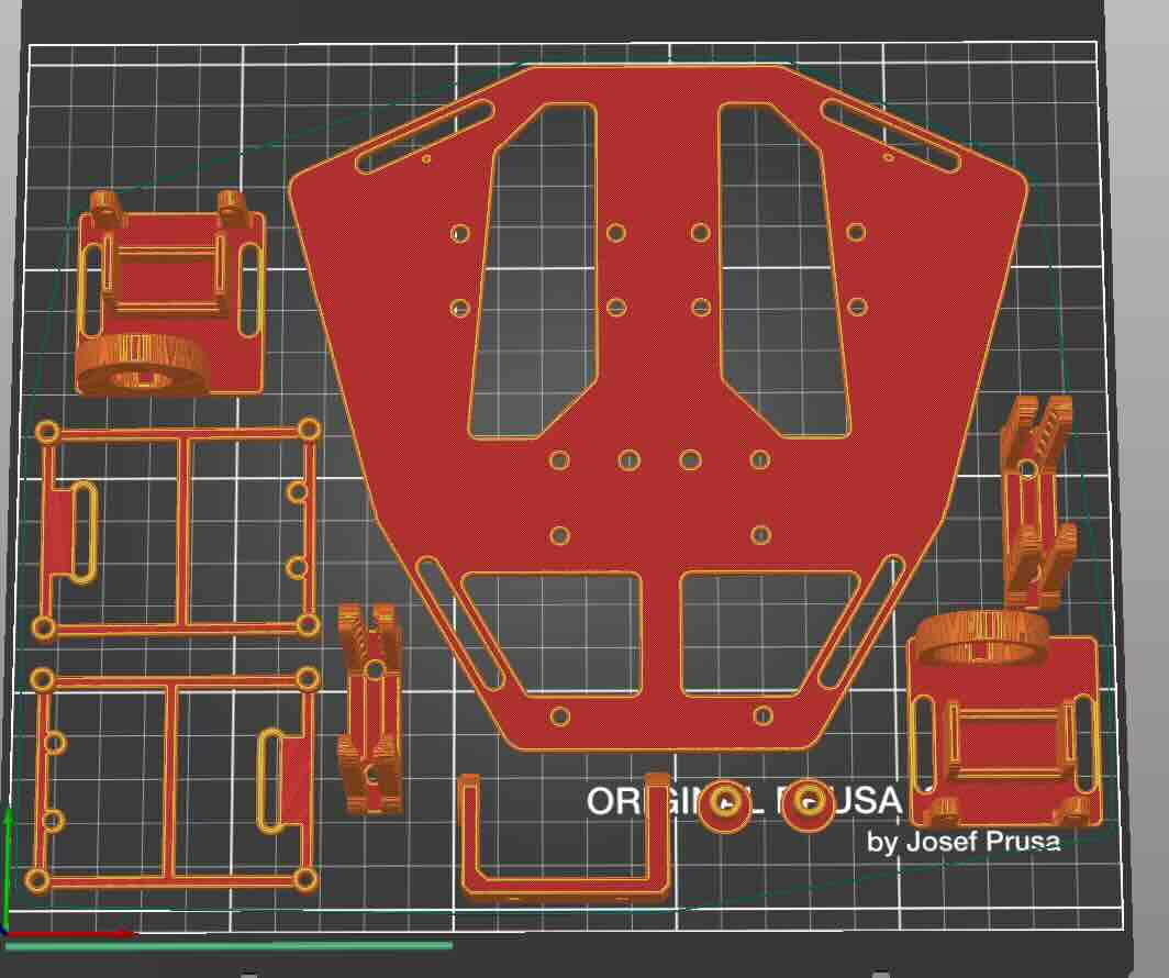
3D printed parts
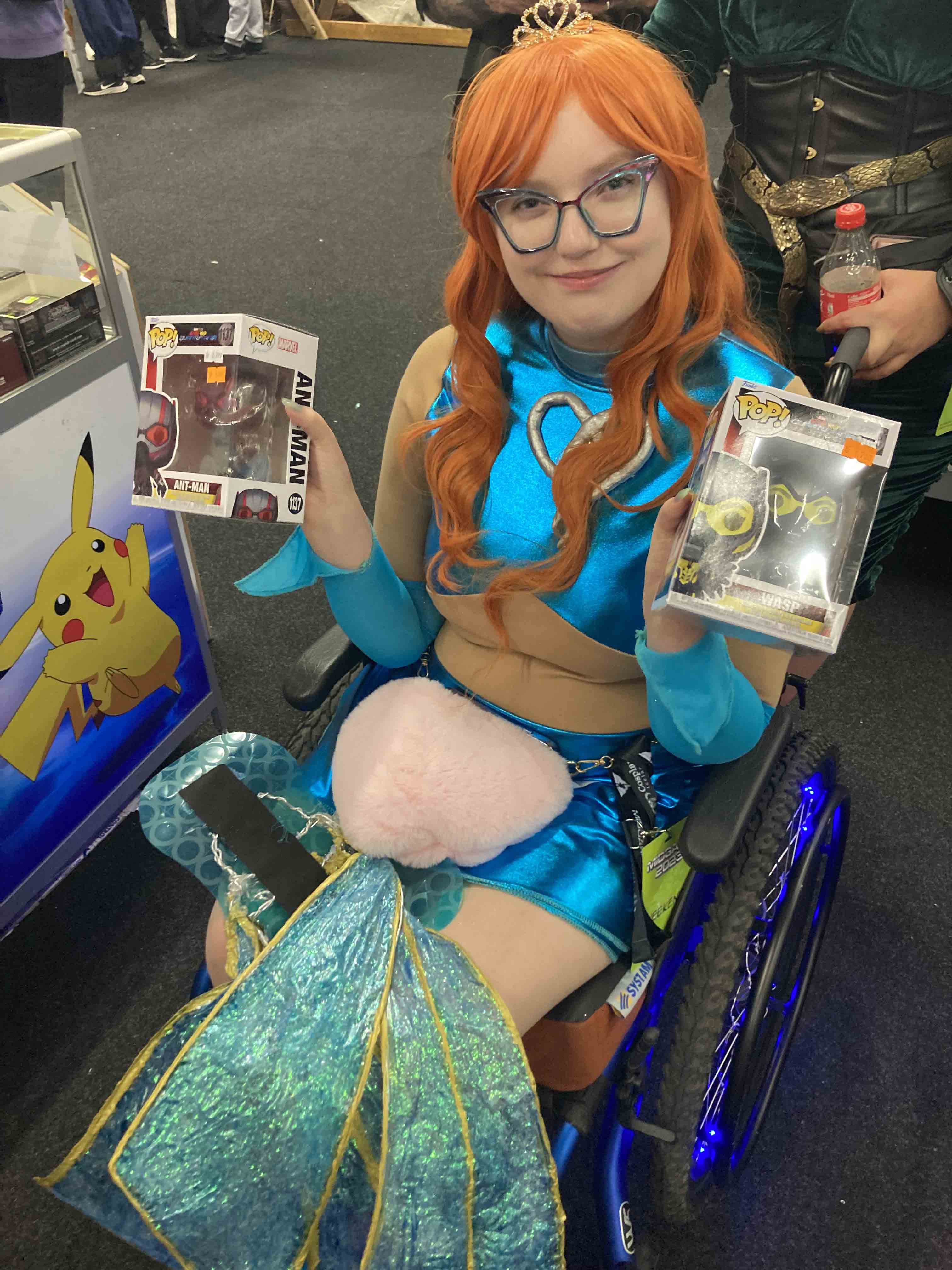
I based my design on wings made by adafruit. Initially I thought I would not need to change a lot of things. But with my wings (made from PETG) I needed more structure and stability. The backplate also hurt my sister so I redesigned so that the straps would hit the shoulders not around the neck. I also changed it so it would not slip. The wing clips didnt add any stability as short as they were so I had to elogate them and print them seperatly with more infill. The PCB board was also my design so it had a different shape than Adafruits. Their mount also had it exposed to the fabric which if it is can snag the material and ruin the back of the costume. I also added a stationary mount so if you want to wear the wings without the anamatronics you can.


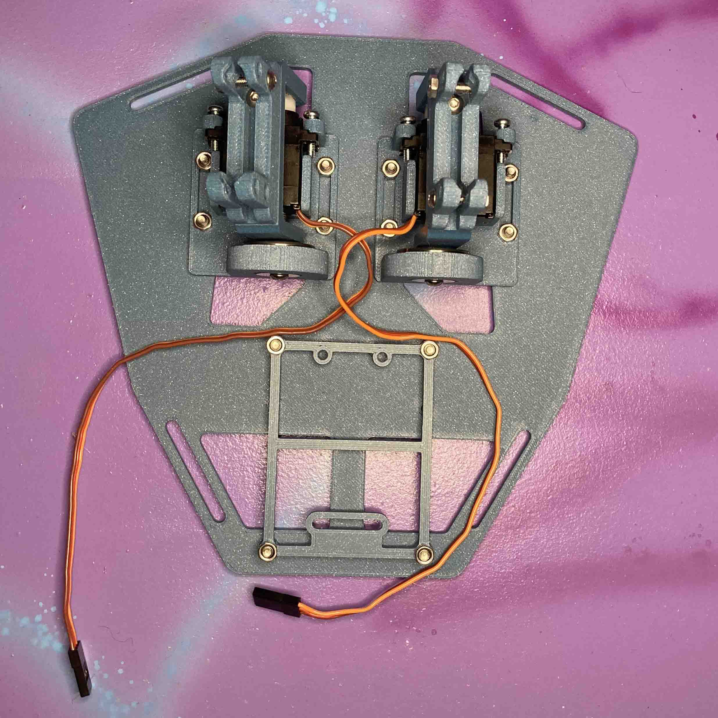
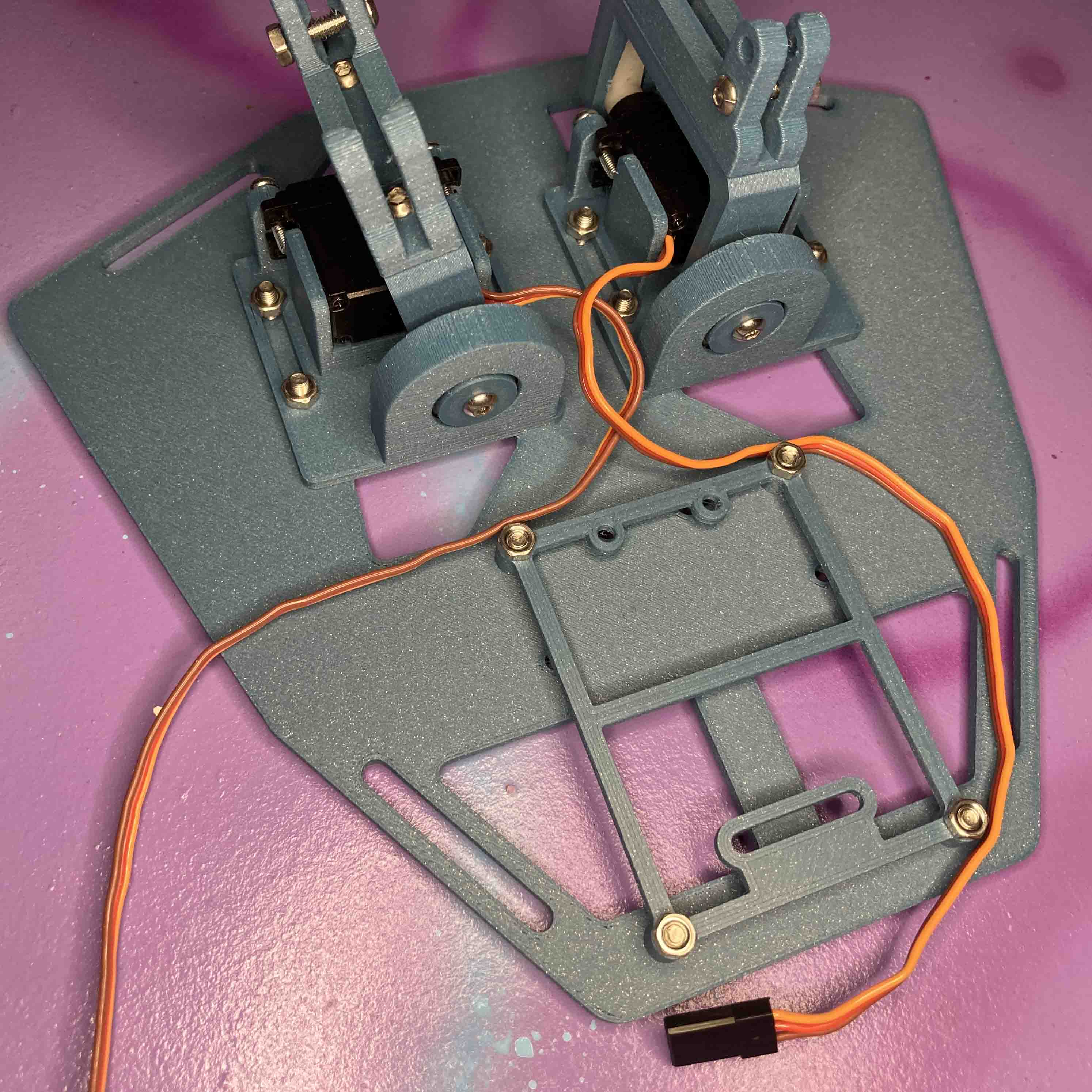
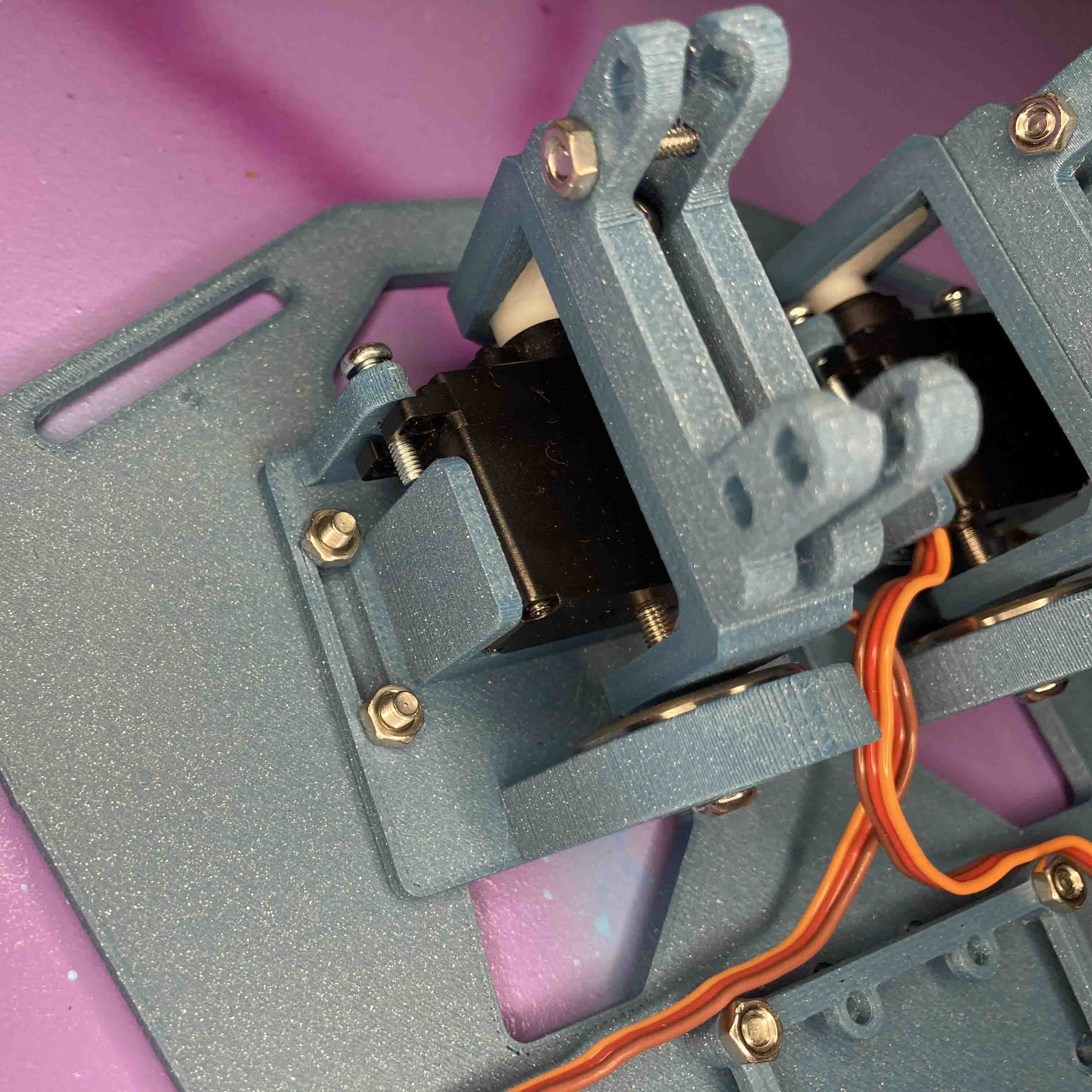
Assembly
The place I got the material in Iceland is 3D Verk .
Item list
| Name | Item 1 | Item 2 | Item 3 | Item 4 | Item 5 |
|---|---|---|---|---|---|
| 1x PCB-Mount | 4x M3 lock nuts | 4x M2.5 x 10mm | |||
| 1x Servo-Holder-A | 1x servo motor. | 2x M2.5 x 8mm | 1x 608ZZ ball bearing | 4x M3 lock nuts | 4x M2.5 x 10mm |
| 1x Servo-Holder-B | 1x servo motor. | 2x M2.5 x 8mm | 1x 608ZZ ball bearing. | 4x M3 lock nuts | 4x M2.5 x 10mm |
| 2x Servo-Arm | 2x M3 x 10mm | 3x M3 lock nuts | 1x servo horn | 2x servo screw | |
| 2x Wing-Clip | 2x M3 lock nuts | 2x M3 x 10mm | |||
| 2x Servo-Pin | 1x M3 x 15mm. | ||||
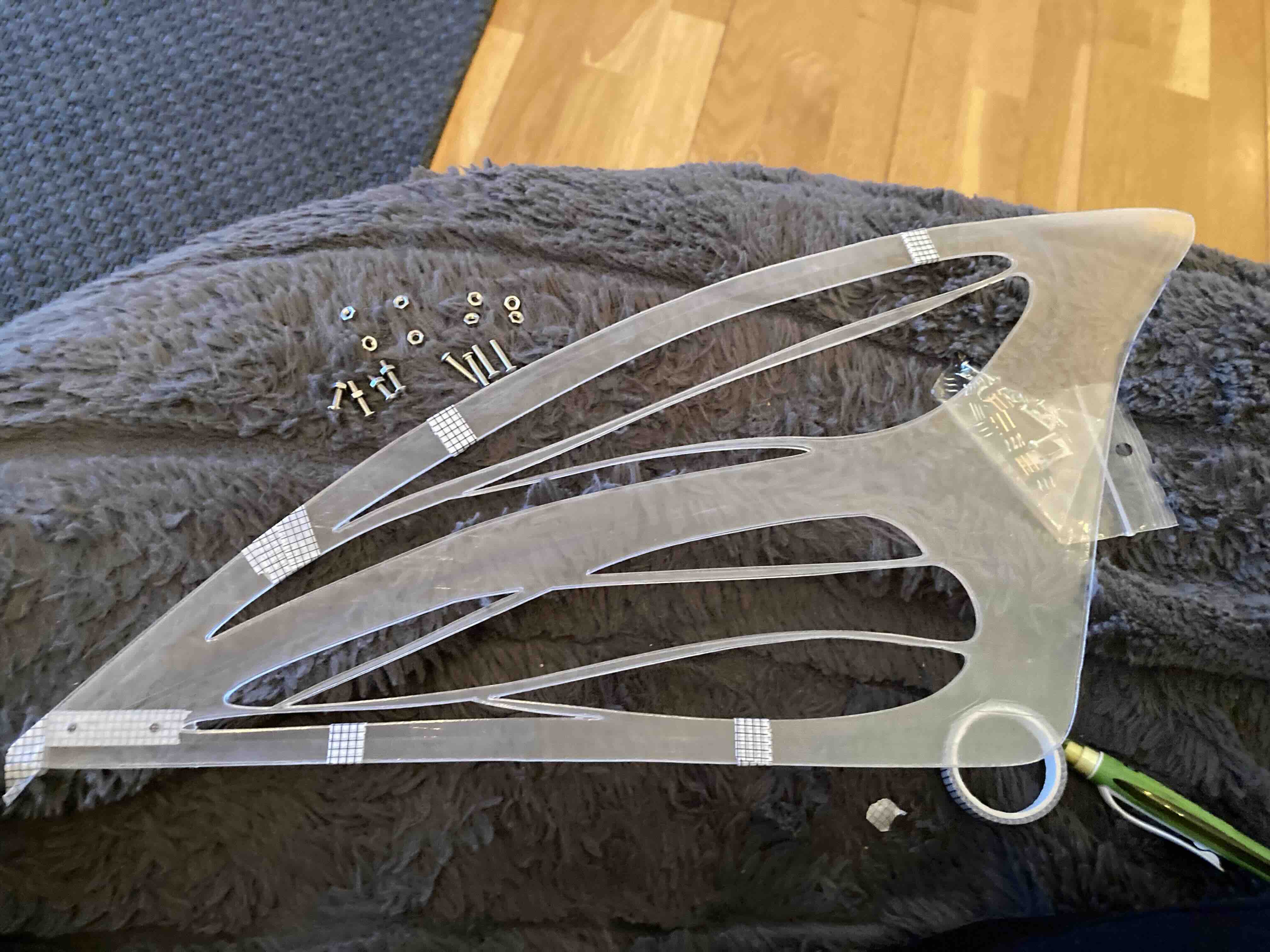
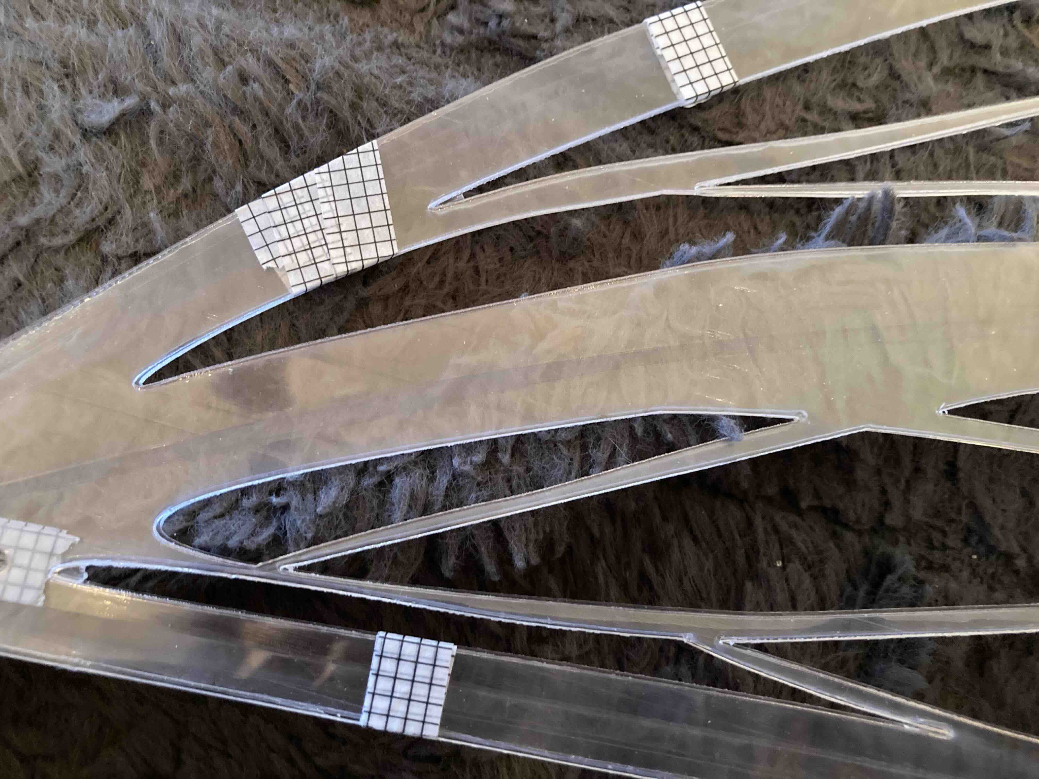
PETG
The place I got the PETG in Iceland was Fást Sketched out part for files.
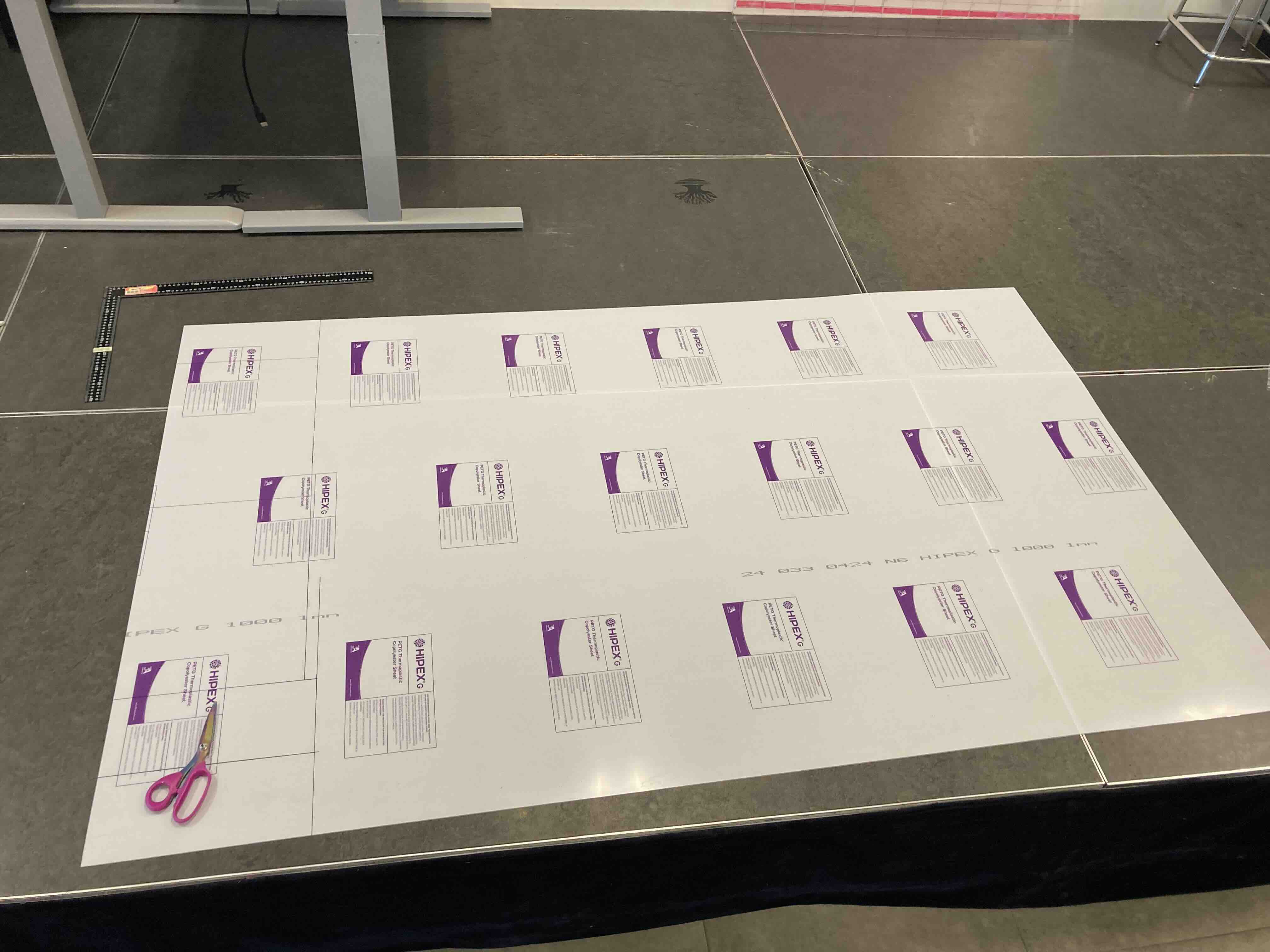
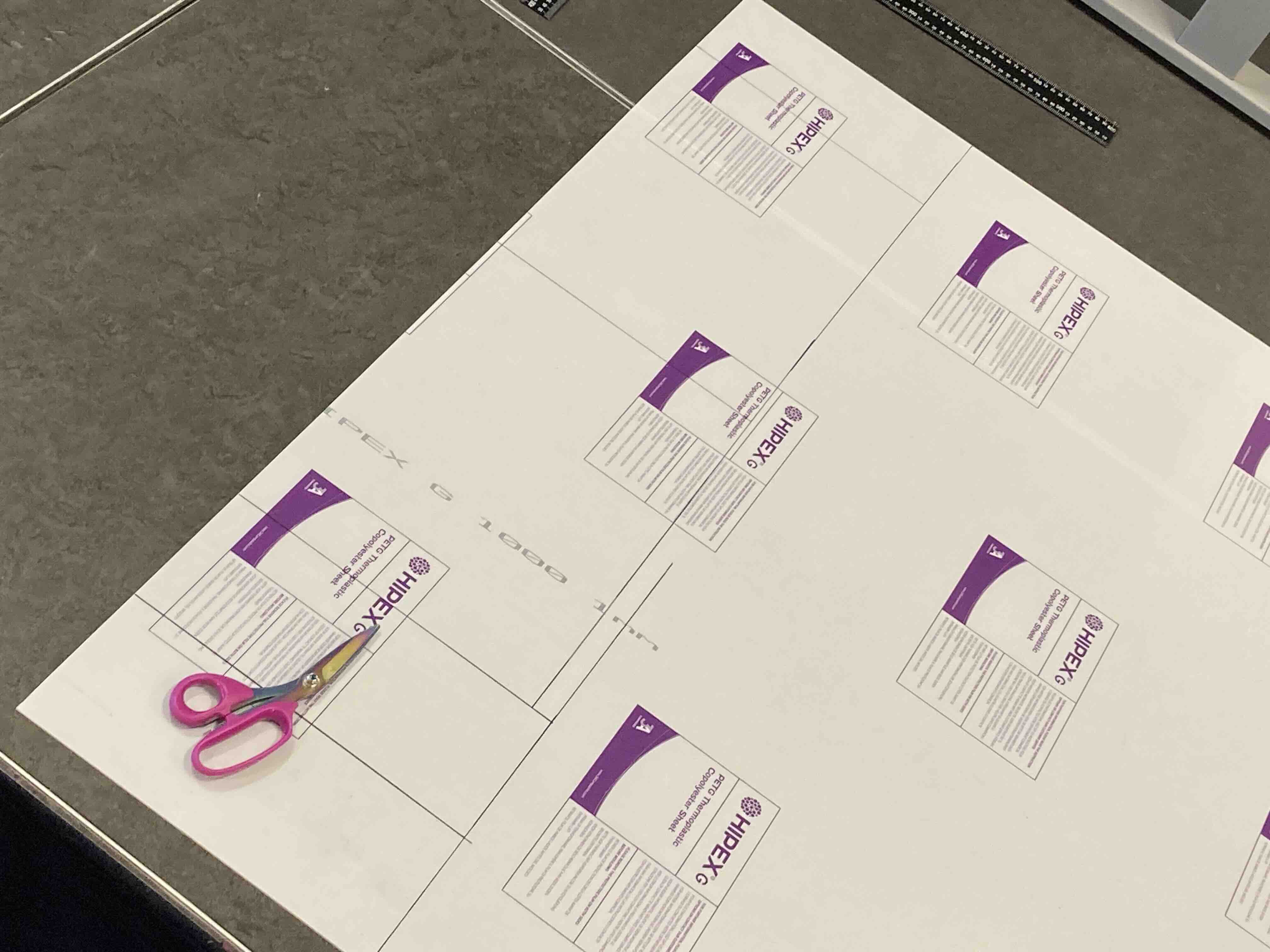
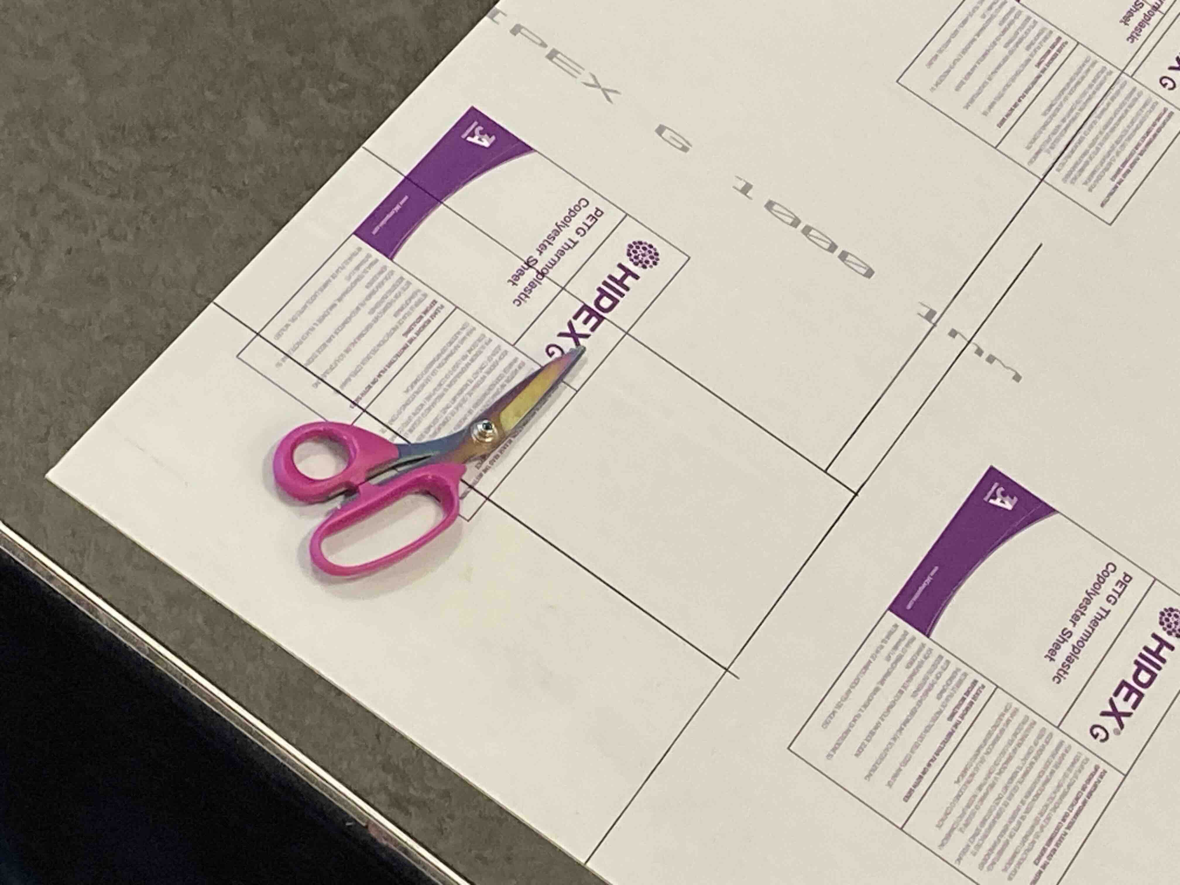
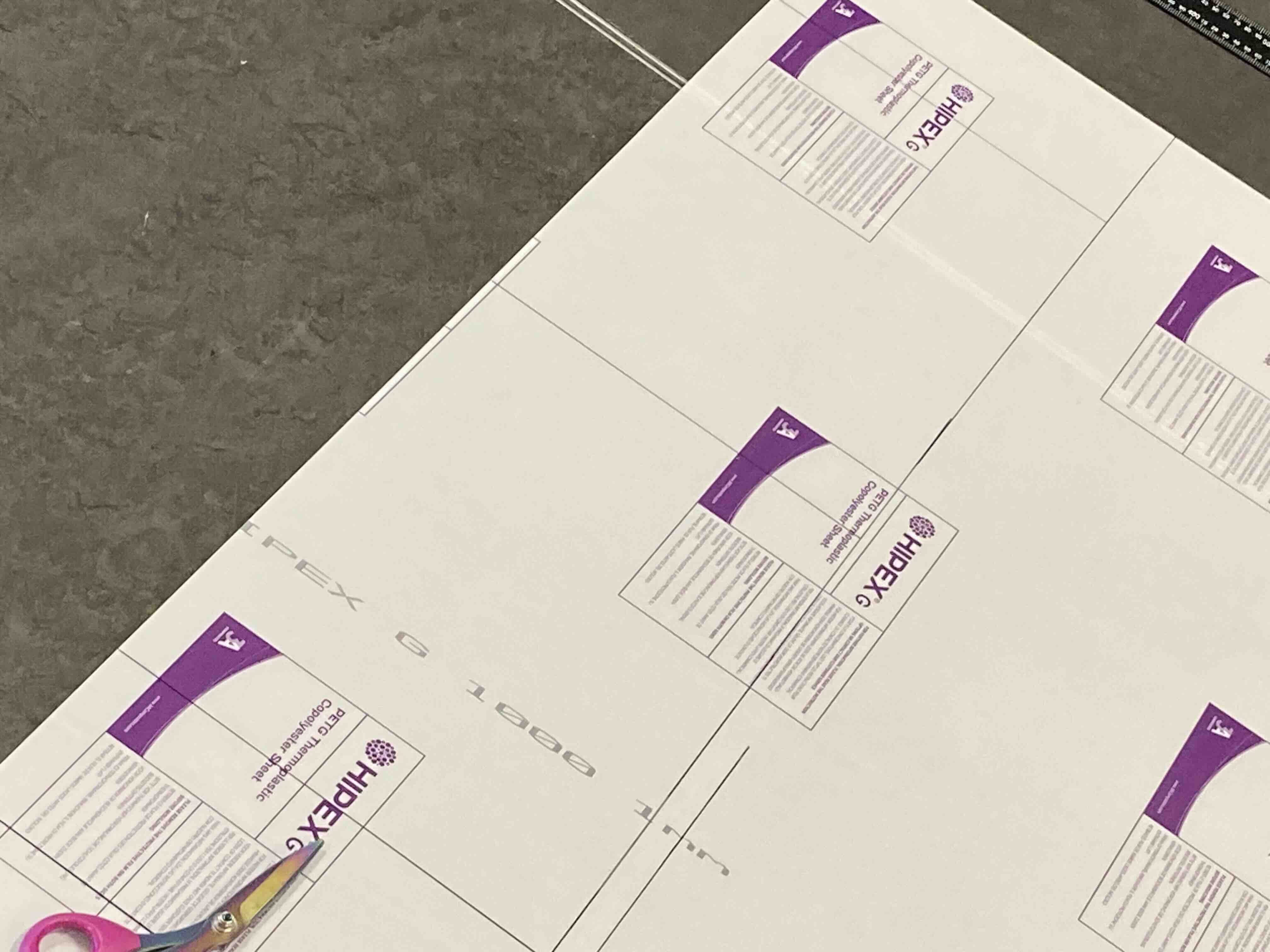
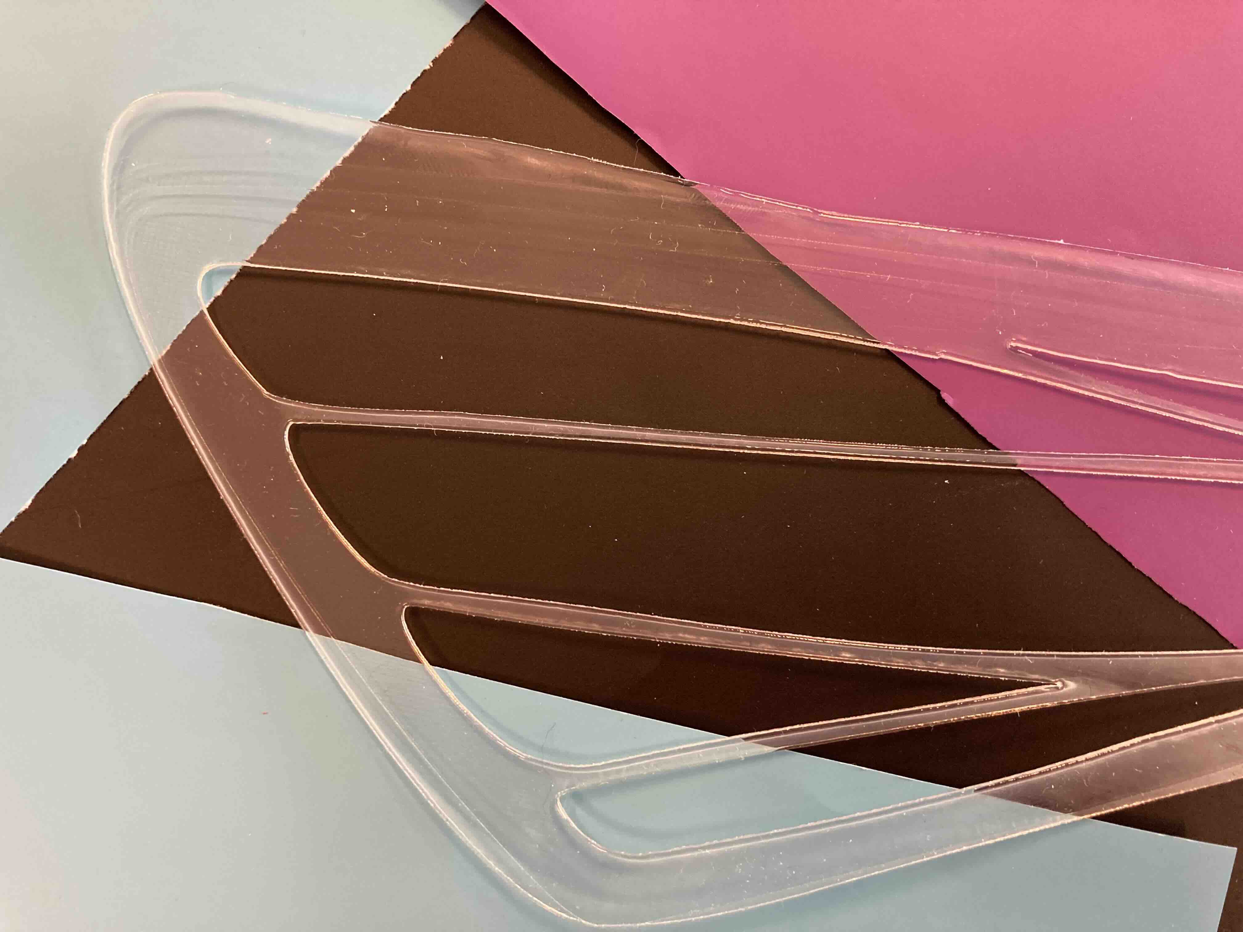
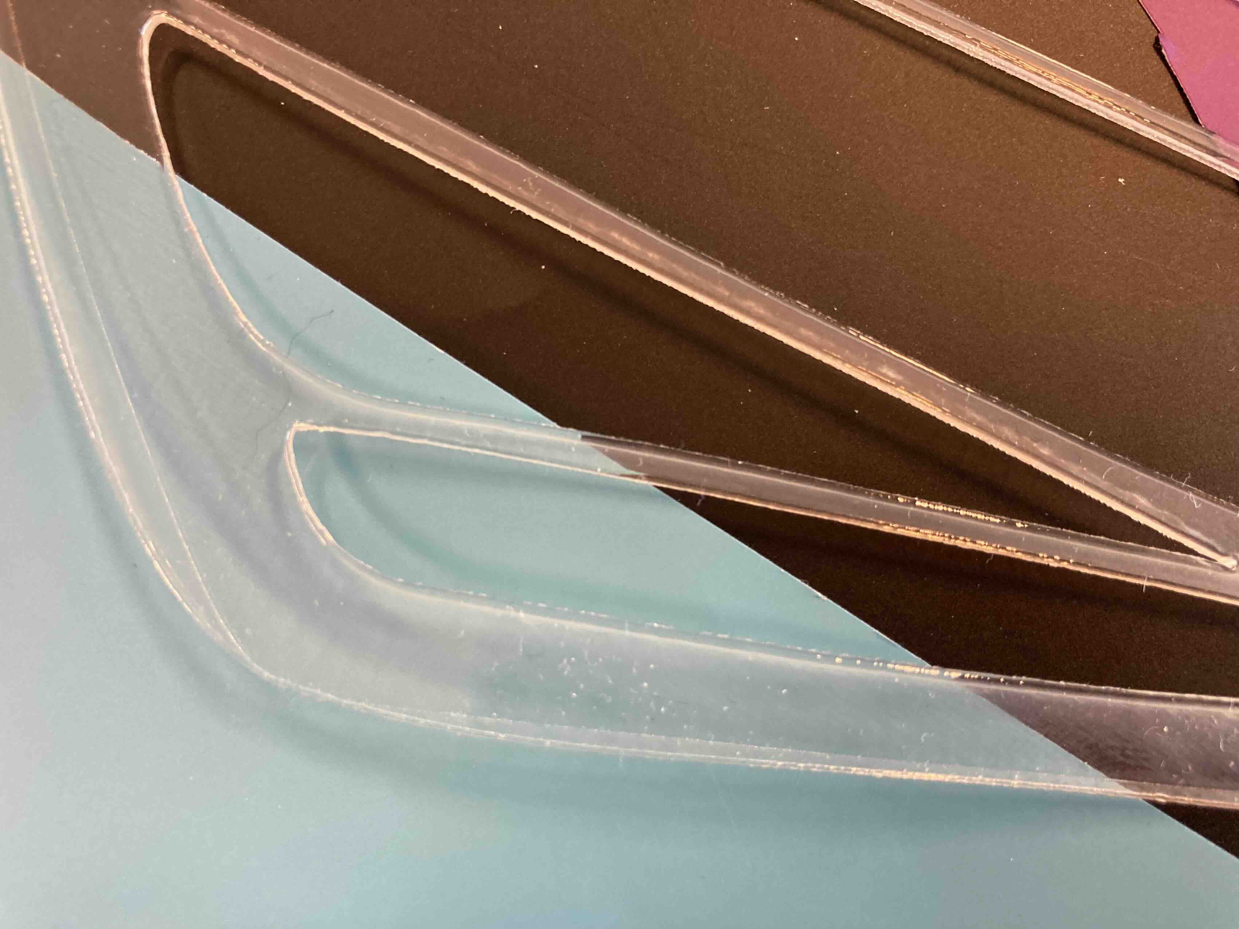
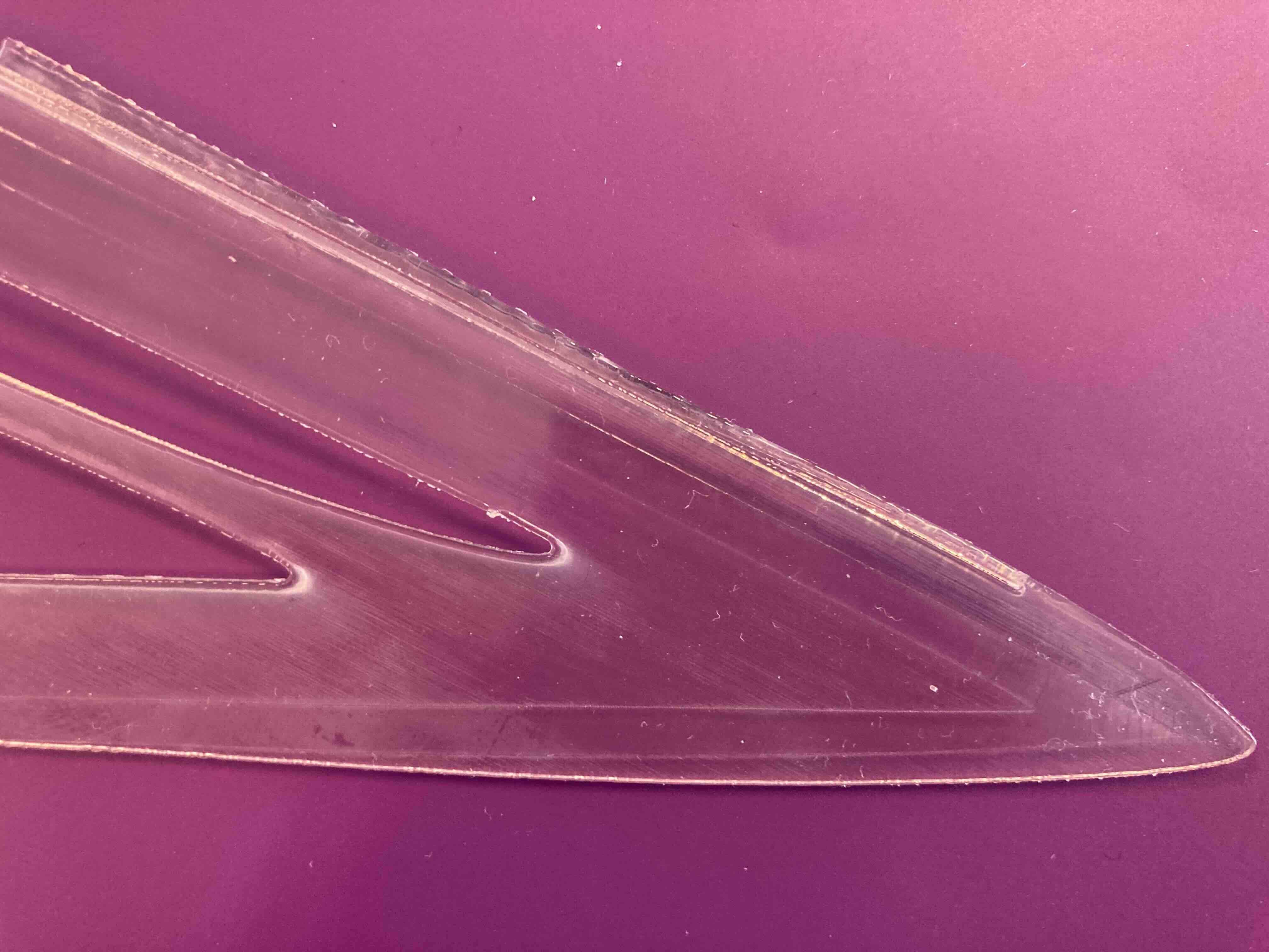
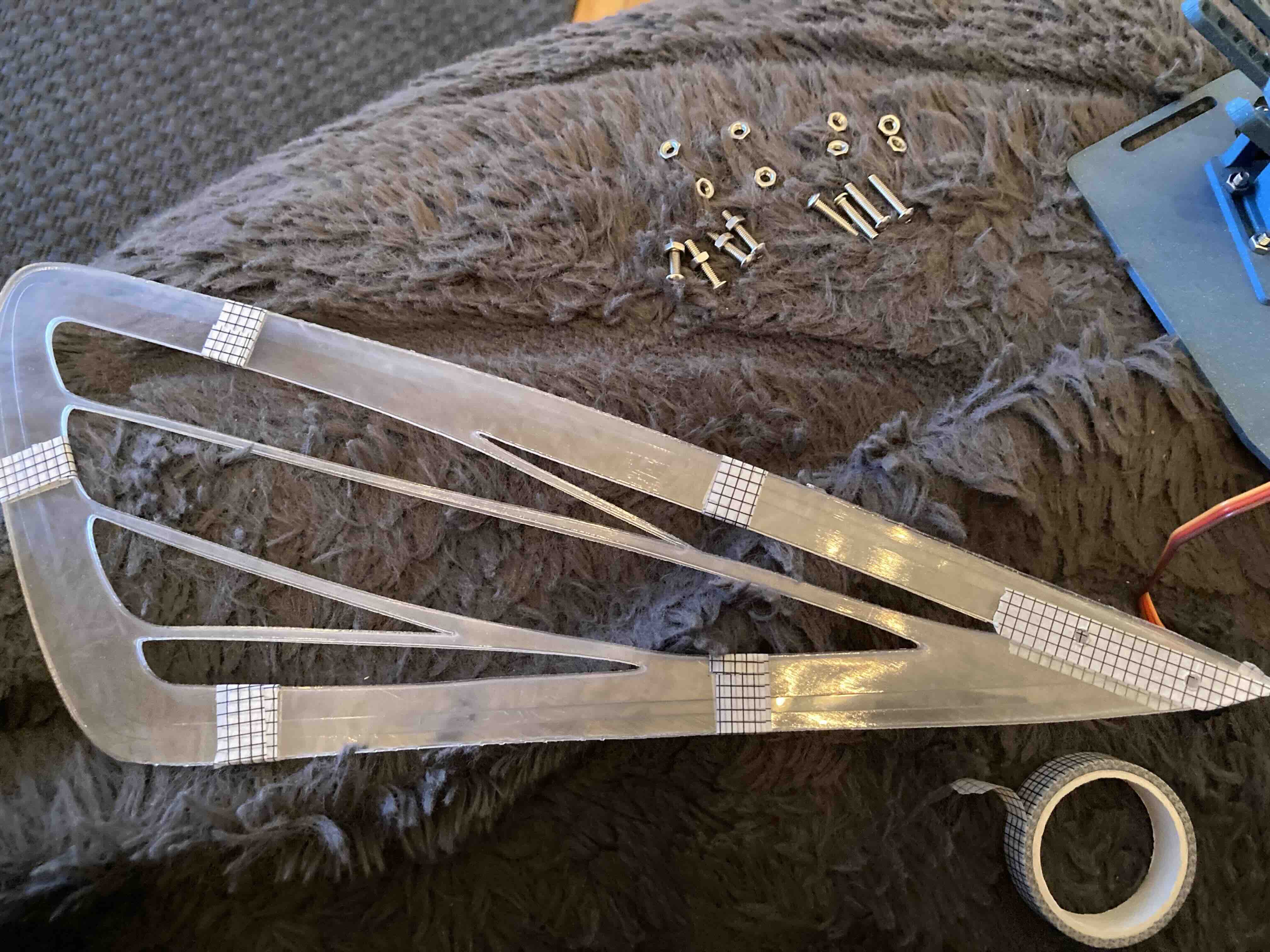
The wing panel journey was not fun. Each new set of wings showed new problems. I thought in the beginning I would burn down the lab since the sparks from the laser were crazy. I will not cut out a new pair of wings until they figure out a better venting situtation for the lab. The whole lab smelled like burned plastic. But now I have them pretty much the way I like them and have figured out the ratio of cut out vs. stability. The main problem will always be the weight the servos can carry. I have also ordered sturdier servos that can carry more weight. The competition wings will be cover in vinyl and have LED lights. The PETG will act as boneing for the wings.
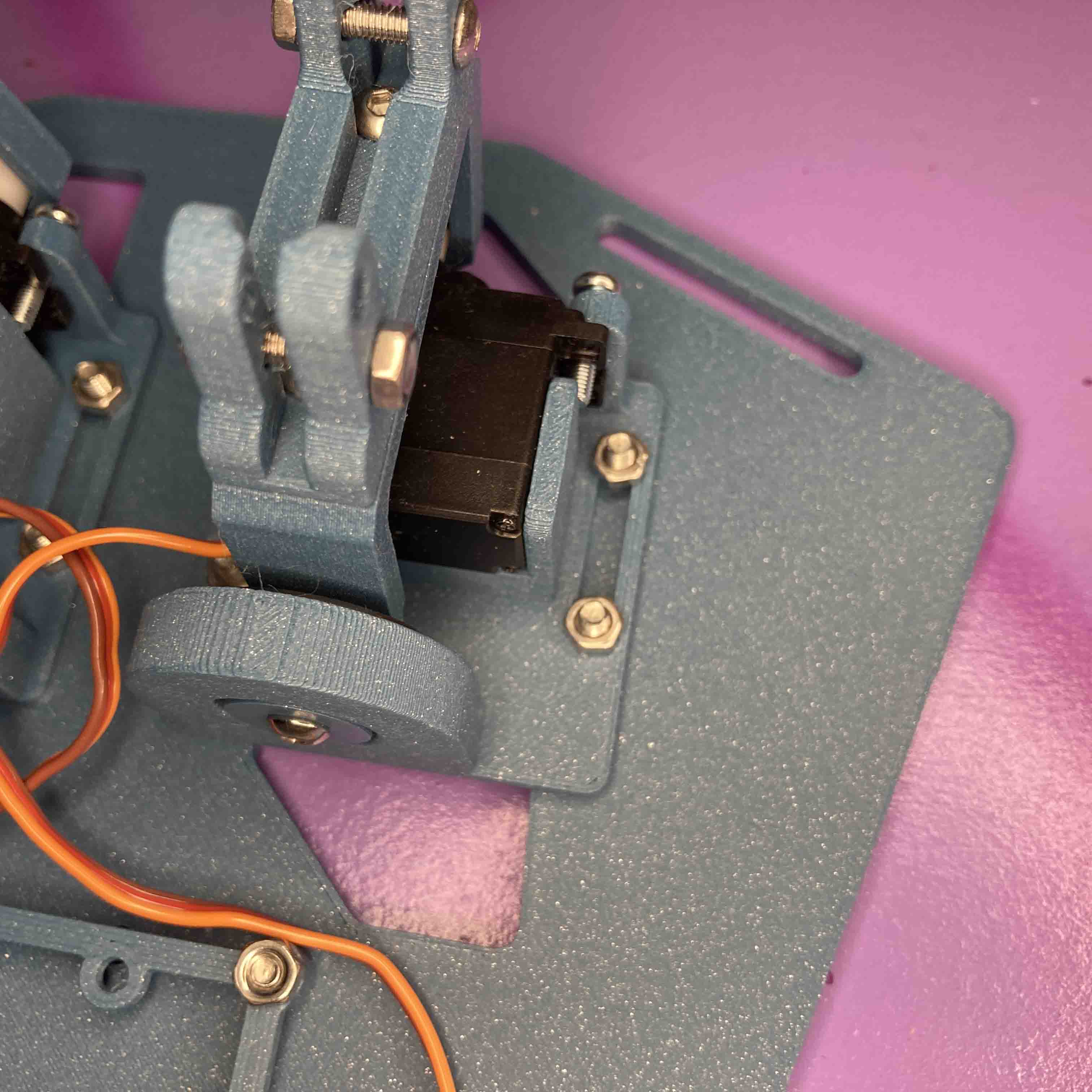
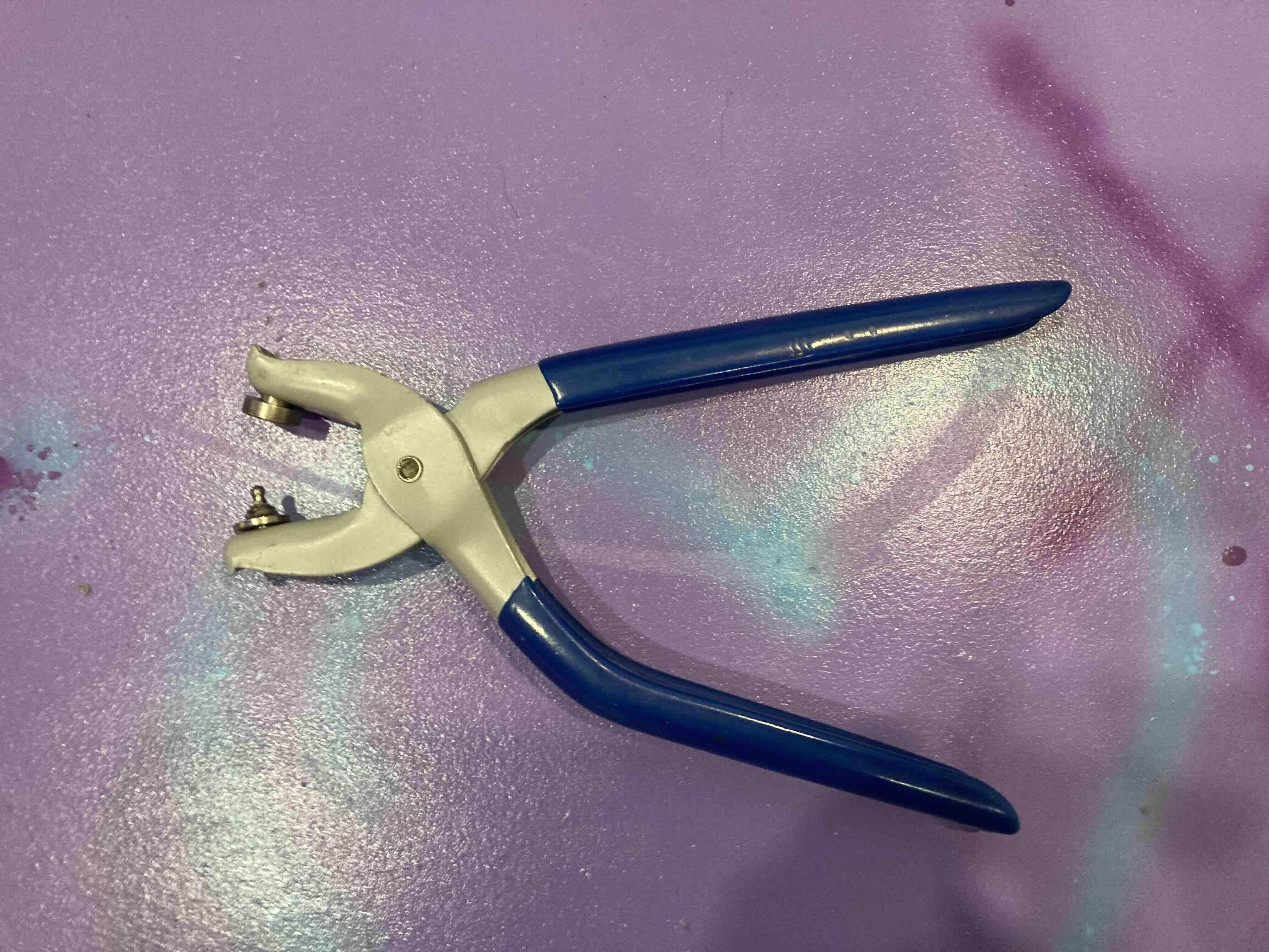
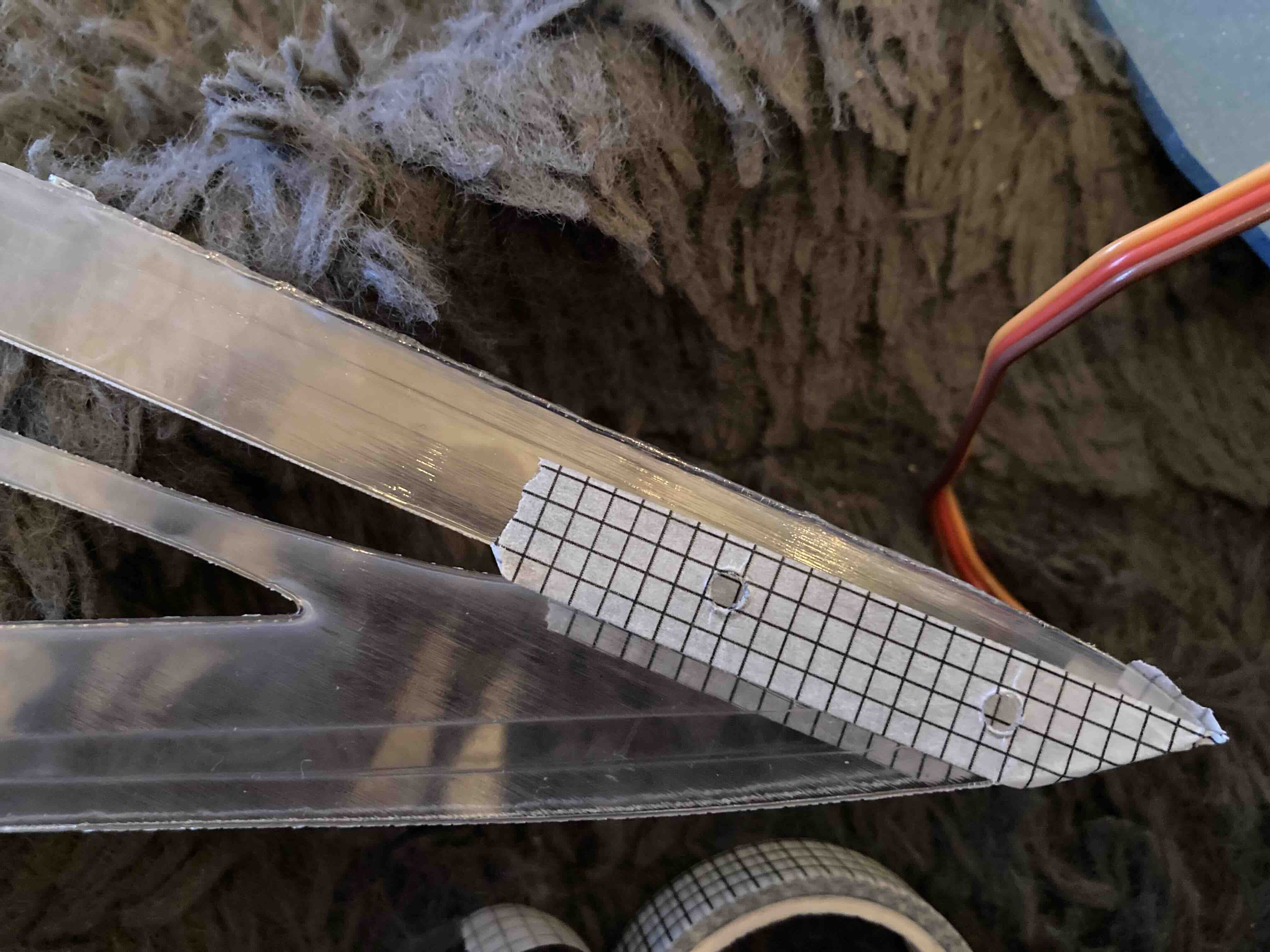
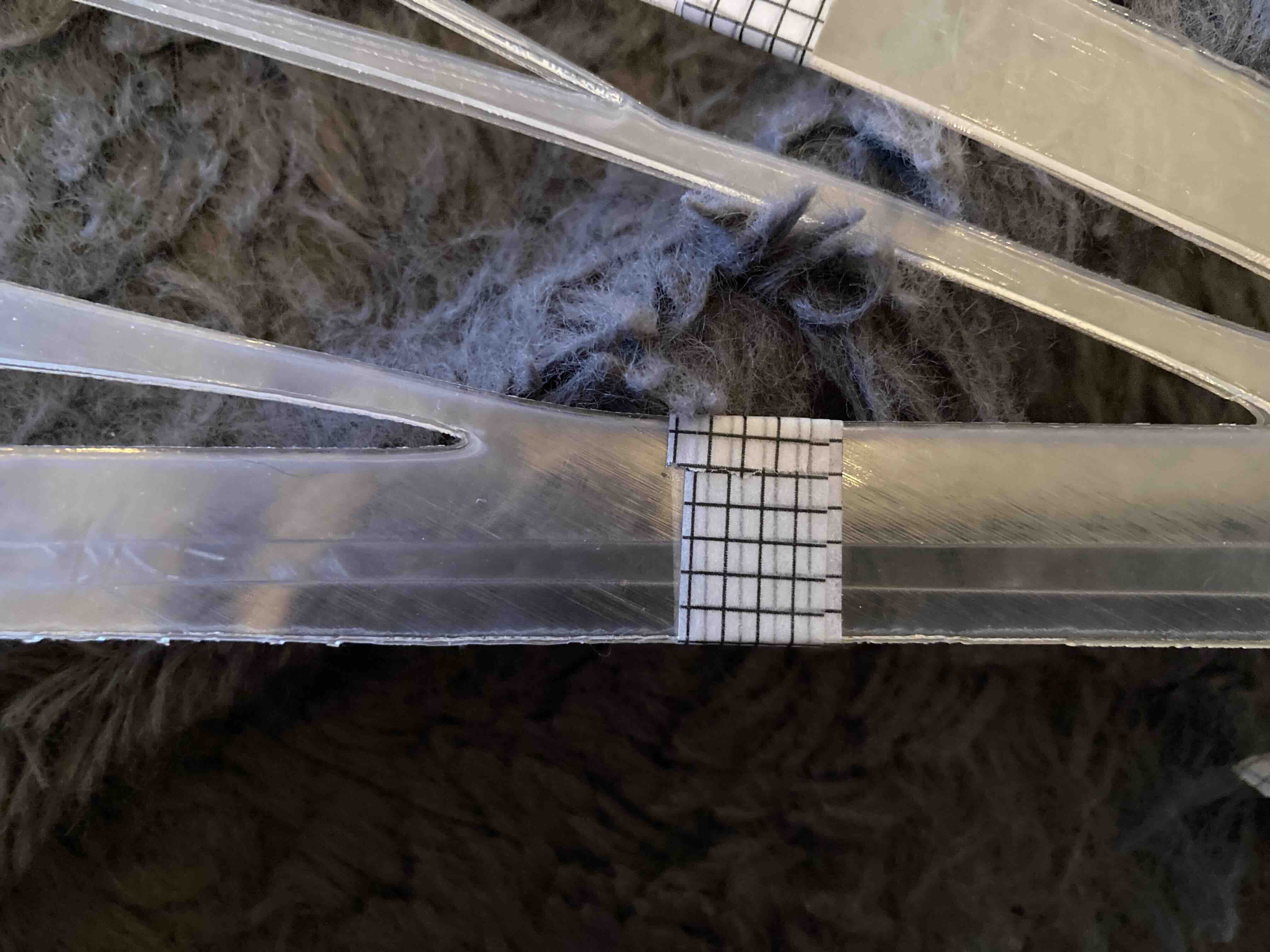
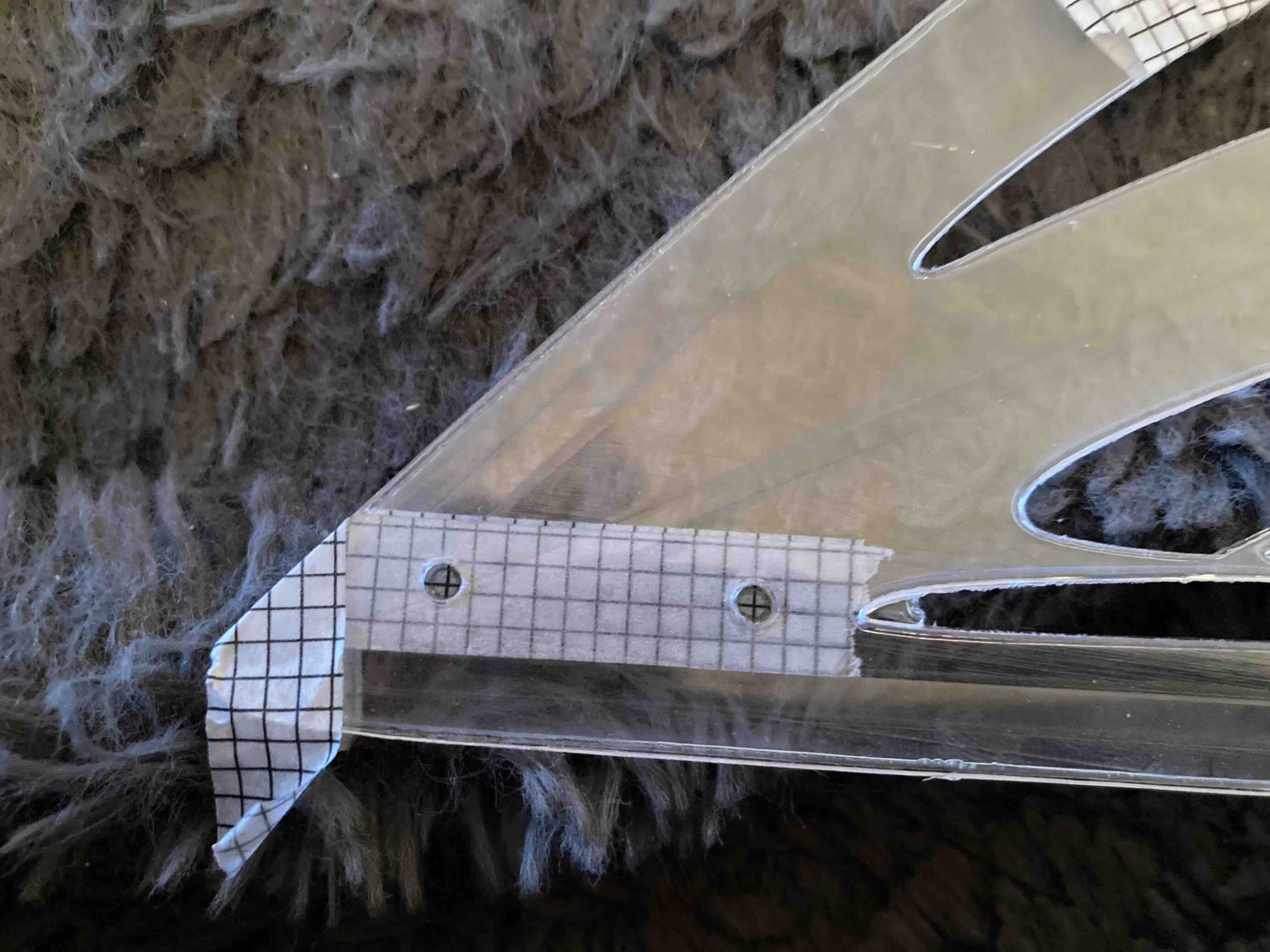
Tool
The tool I used to mark and make the hole for the wing clip.
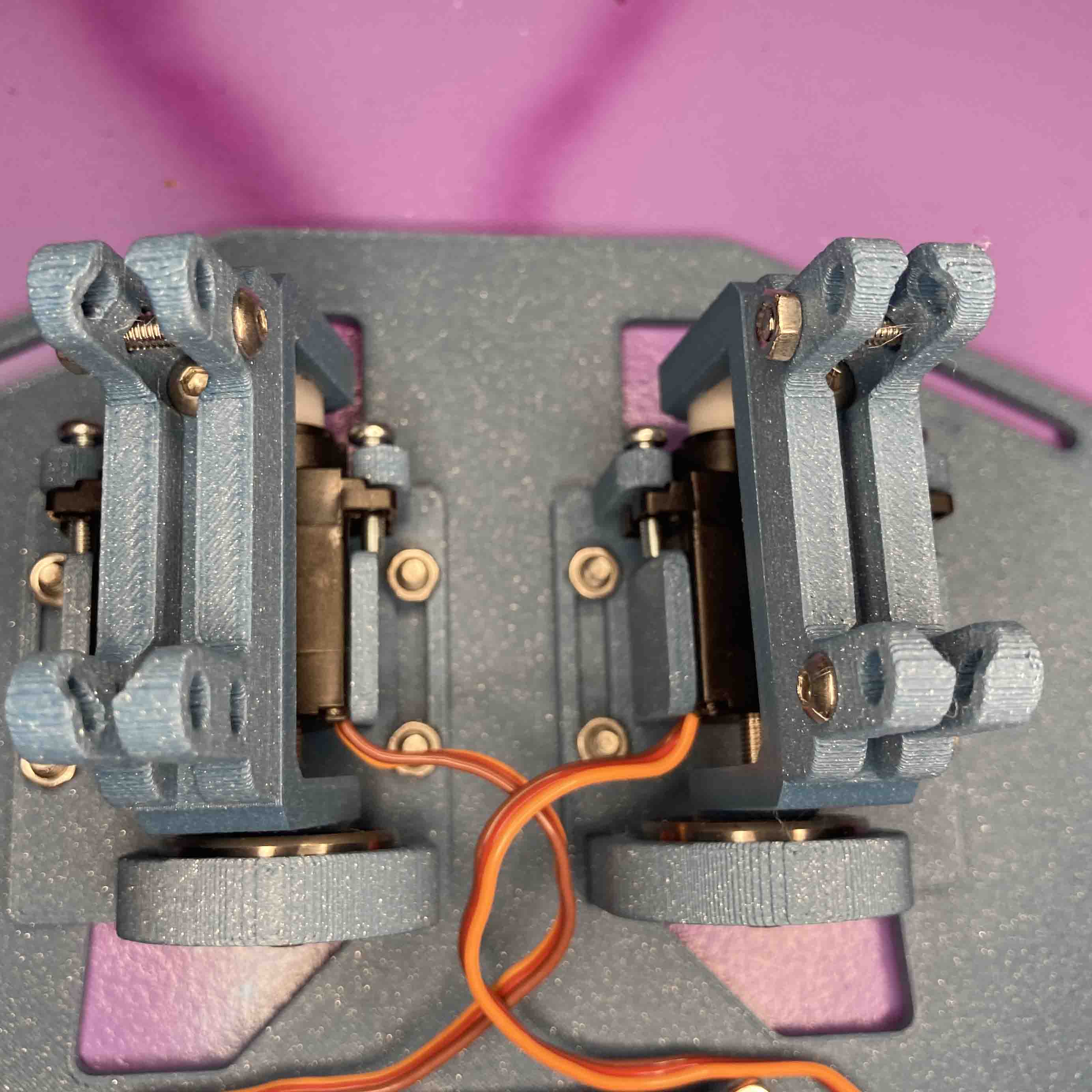
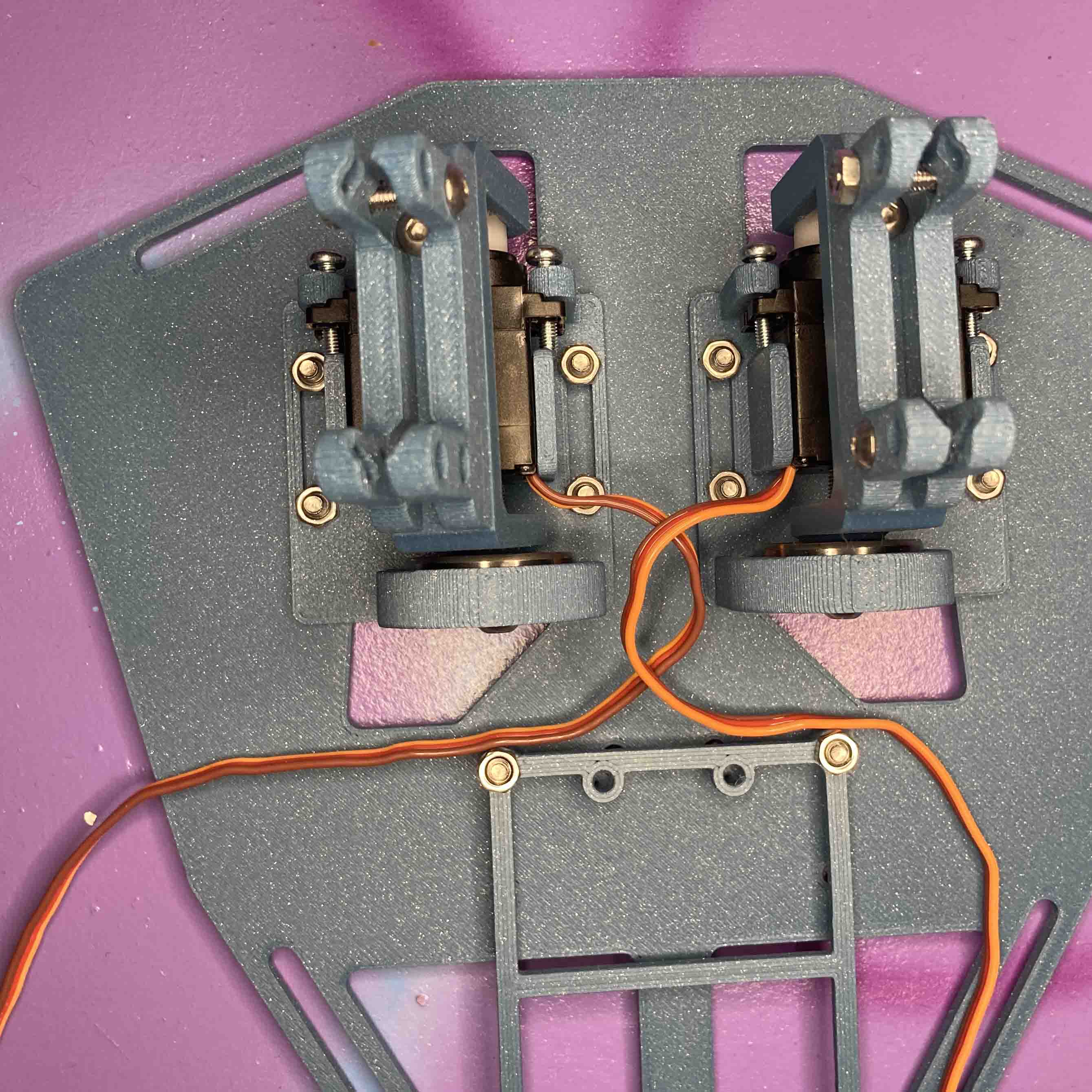
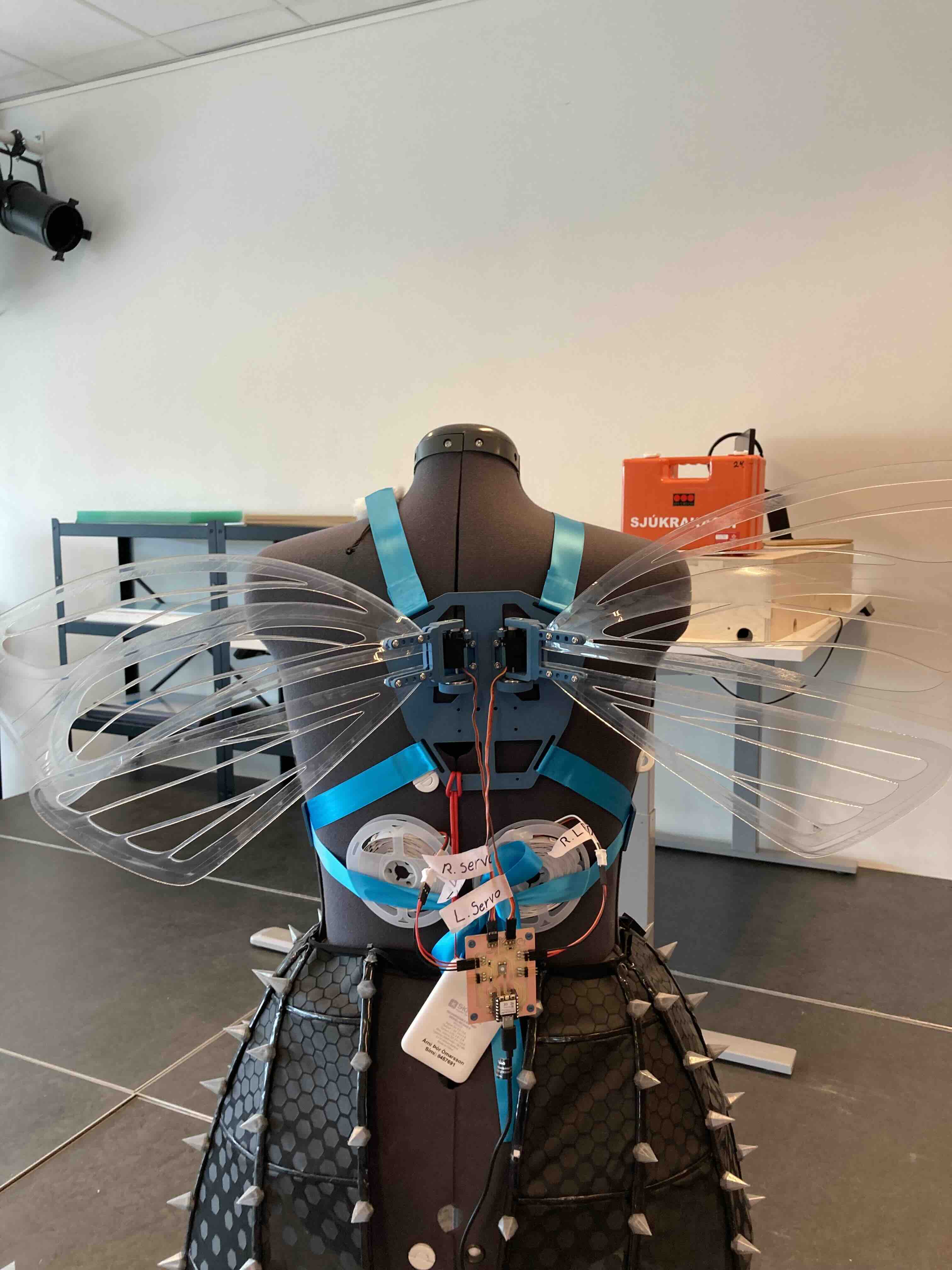
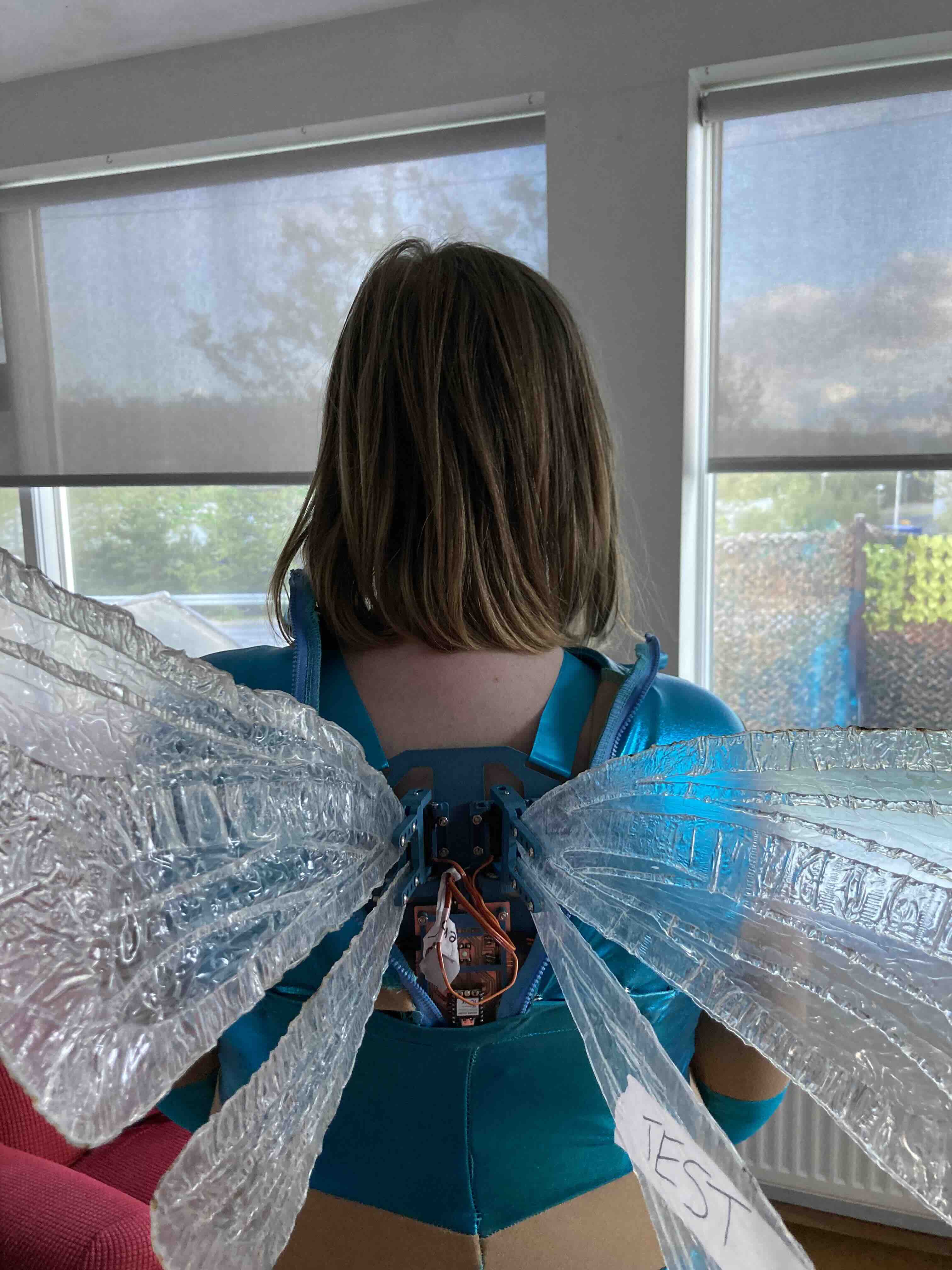
All parts assembeled
All parts assembeled on a maniquin. Use screws to hold the wings in plac.
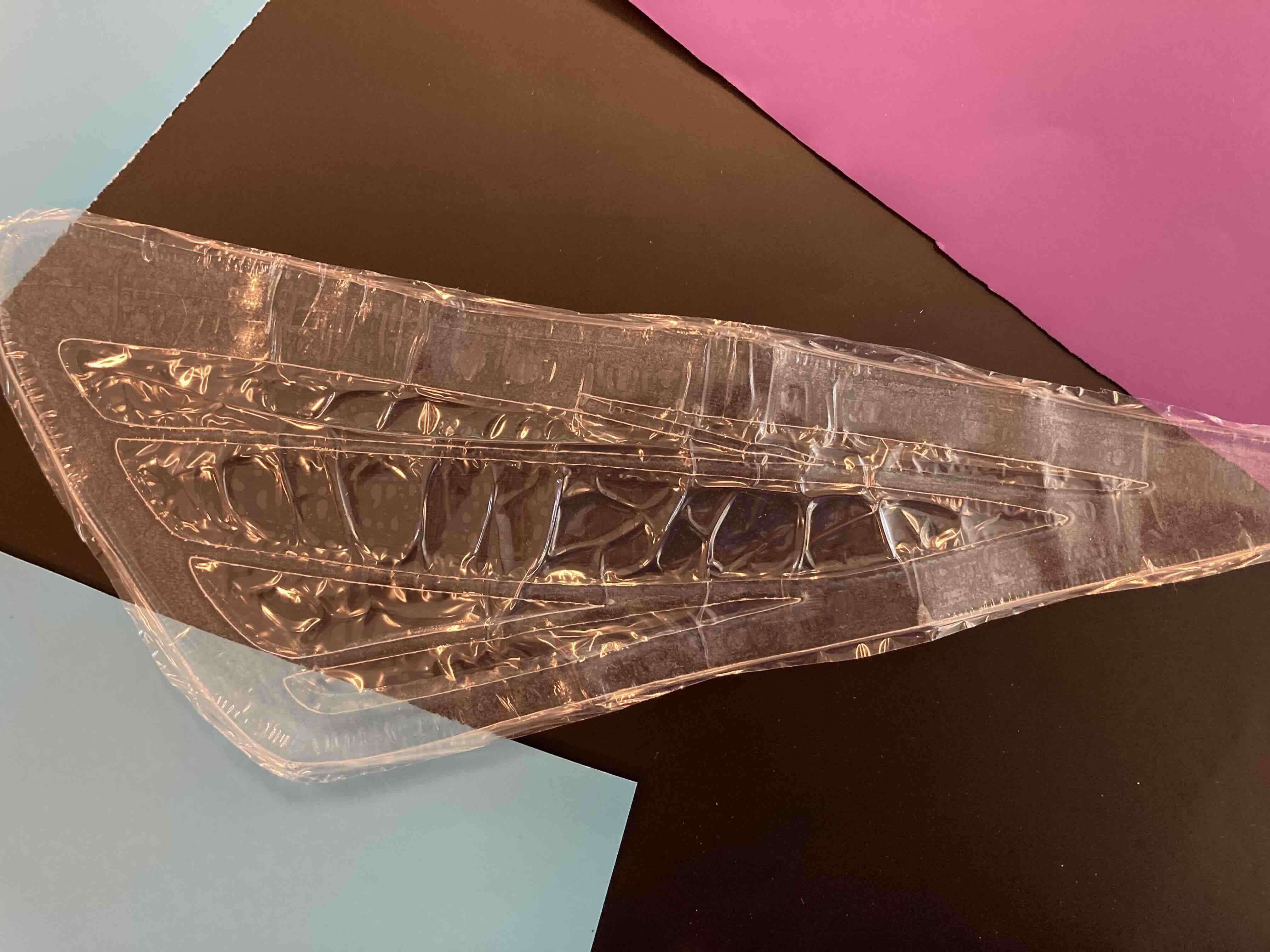
Wrapped wings.
Needed to be repunched since the material shrank in the heat press.
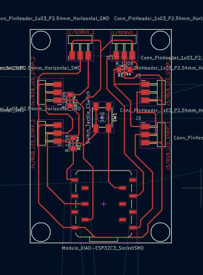
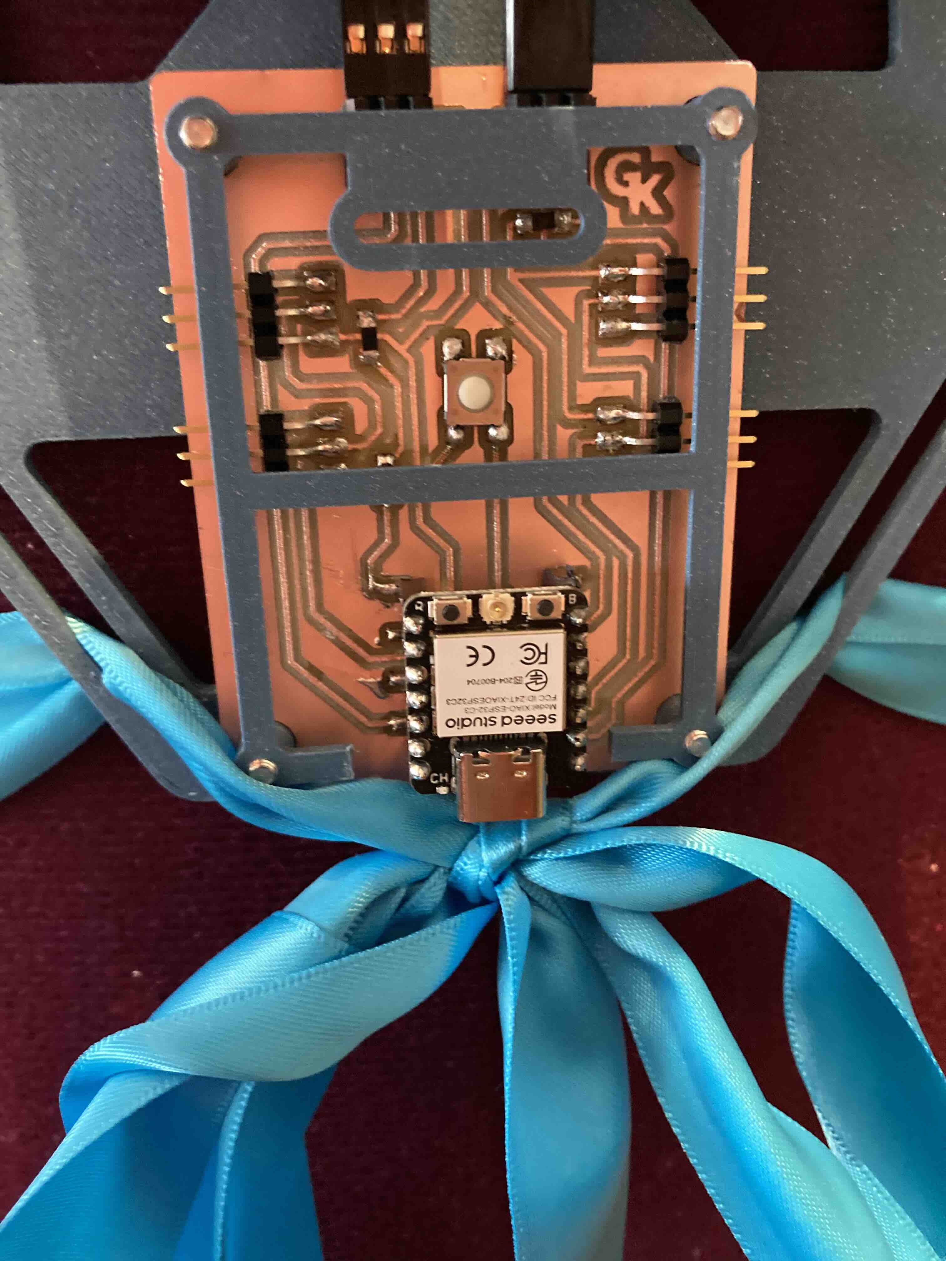
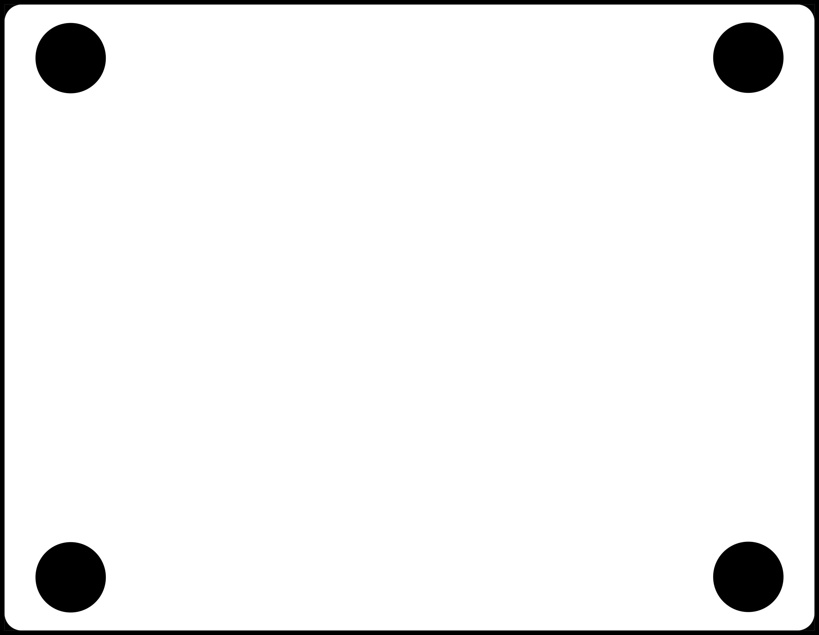
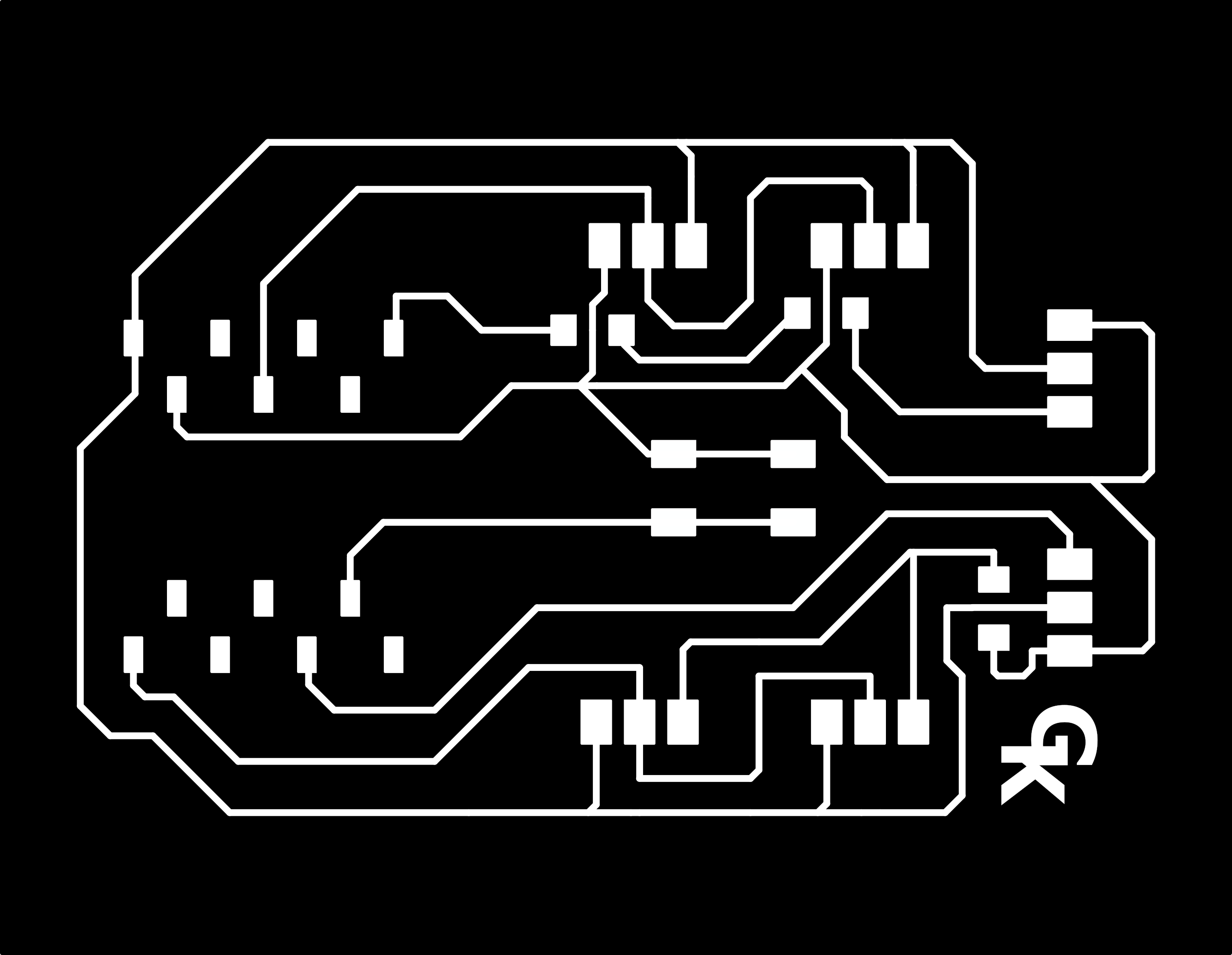
KiCad: PCB XIAO with socket.
PCB used in final version. Helps to show where parts go on the board.
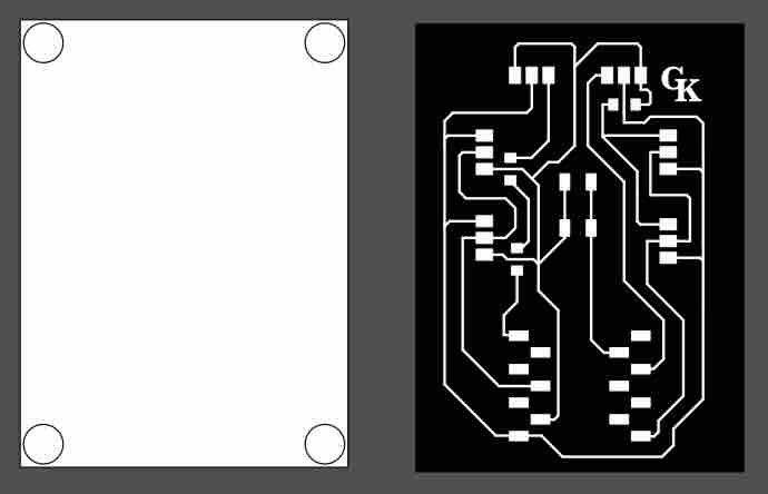
Inkscape
Inkscape/milling
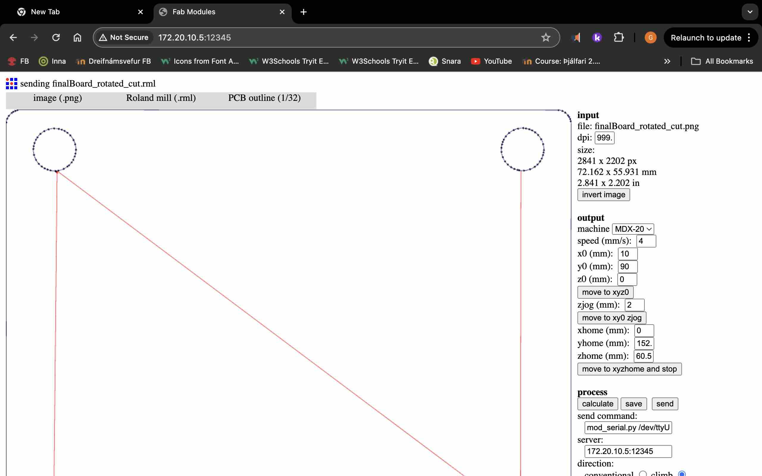
I started with downloading a file that and tell a pattern for the board. I opened the file and Incscape I made minor changes. I change the logo to my initials. Then I made a white box to put behind the file. When was done I exported the files made sure the DPI was set to 1000 then I moved the top layer to see only the white box exported the white box made sure that the DPI was set to 1000 I moved both files to my USB drive. I made the toolpath by working with a svg file in InkScape and saving that one as PNG fle. I then imported the file to fabmodule and make the G-Code. I pushed calculate on fabmodule to make the toolpath.
Milling
I got help with putting double sided tape on the back of the copper board the top double sided tape needed to lie next to other but not overlap. Remove the film of the double sided tape and attached the copper board to the copper board, that‘s attached to the roland modela mdx-20 to make sure the board doesn‘t warp. Spray the board with ropping alcohol and to clean the fingerprints.
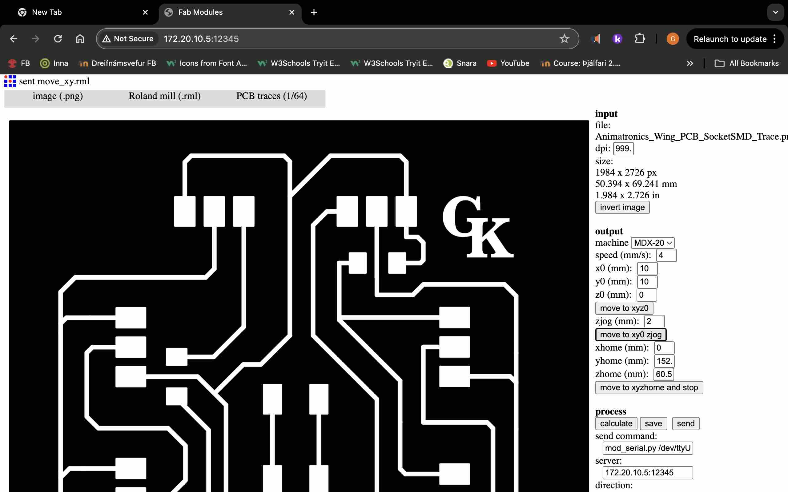
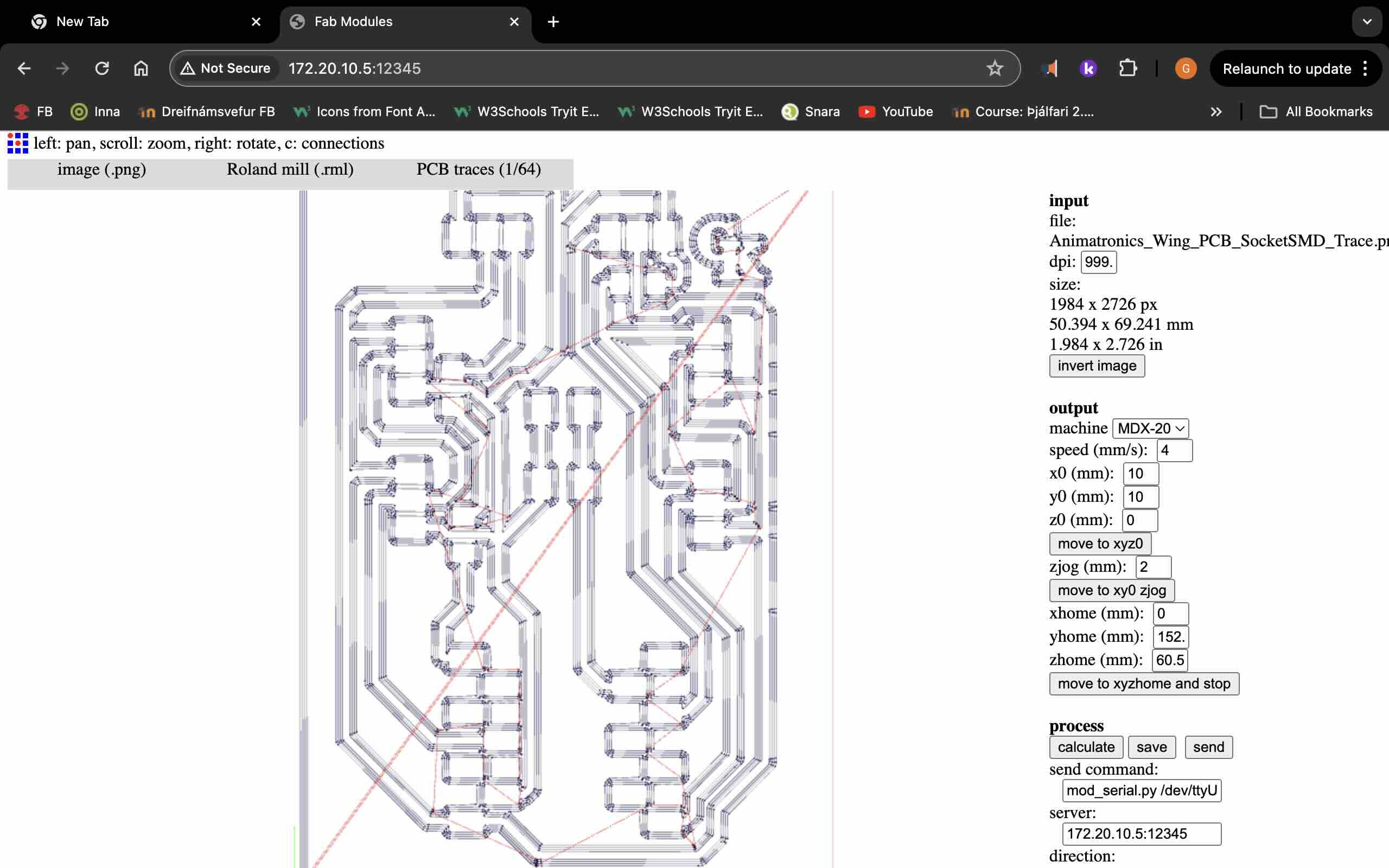
Input: you first set the board size (the dimensions) and DPI (desired resolution(Dots Per Inch)). Then invert the image. Output: Select the mashine (MDX-20, Adjust the milling speed), Configure XYZ home (the starting point), Move to home (Hit move to xyz0 to move to home, set x0 y0 z0. The move to xyz0 moves to home but keeps the milling at a safe distance from the board 2mm), Safe ZJog (for safety). Process: Here you need to change the server ip port to match the hosting server. Keep other settings as defult and unchanged (self explanatory). The calculate button creats the tool path. Final step: Hit send to begin the milling process, monitoring the mashine to ensure proper operations.
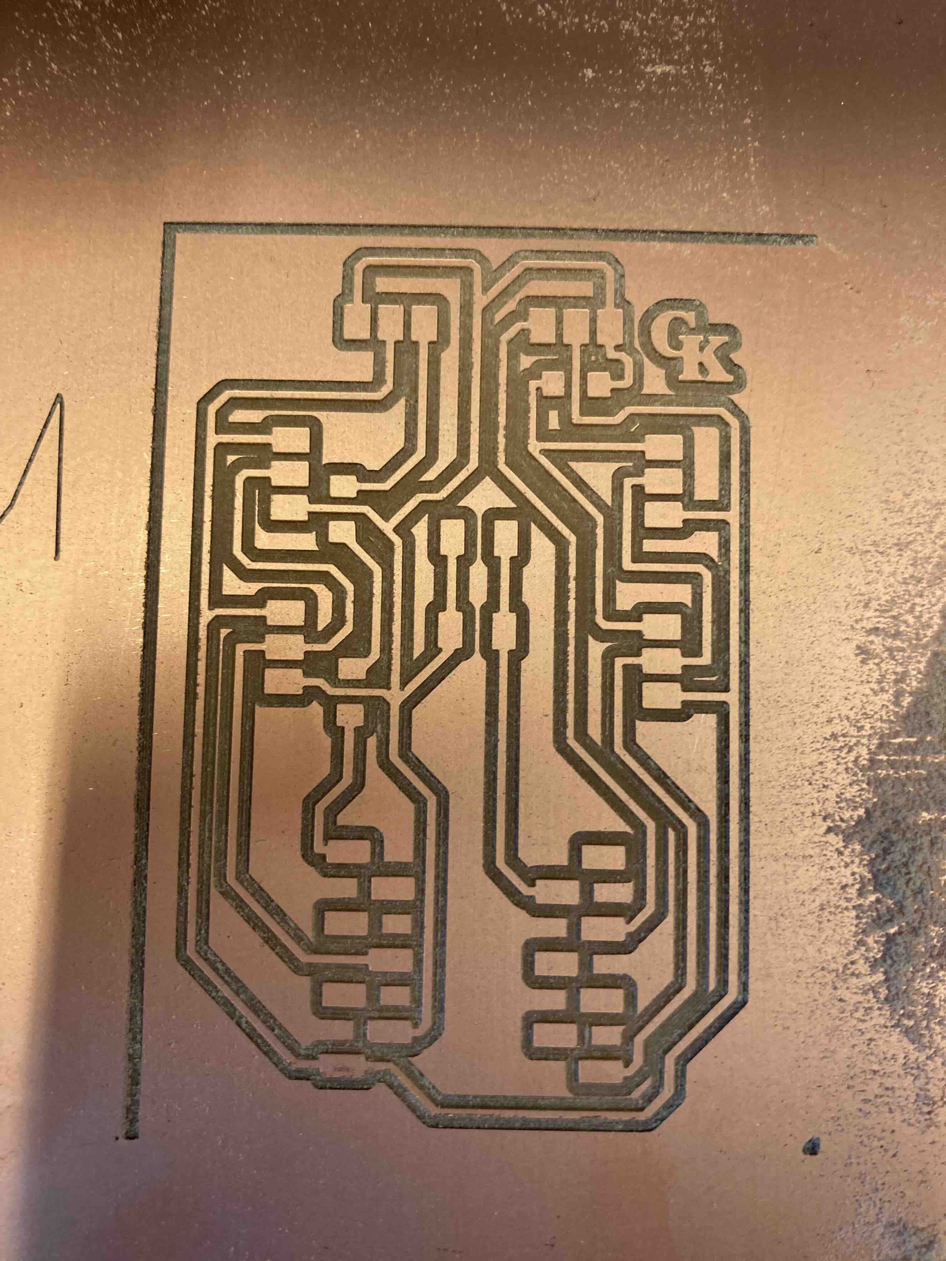
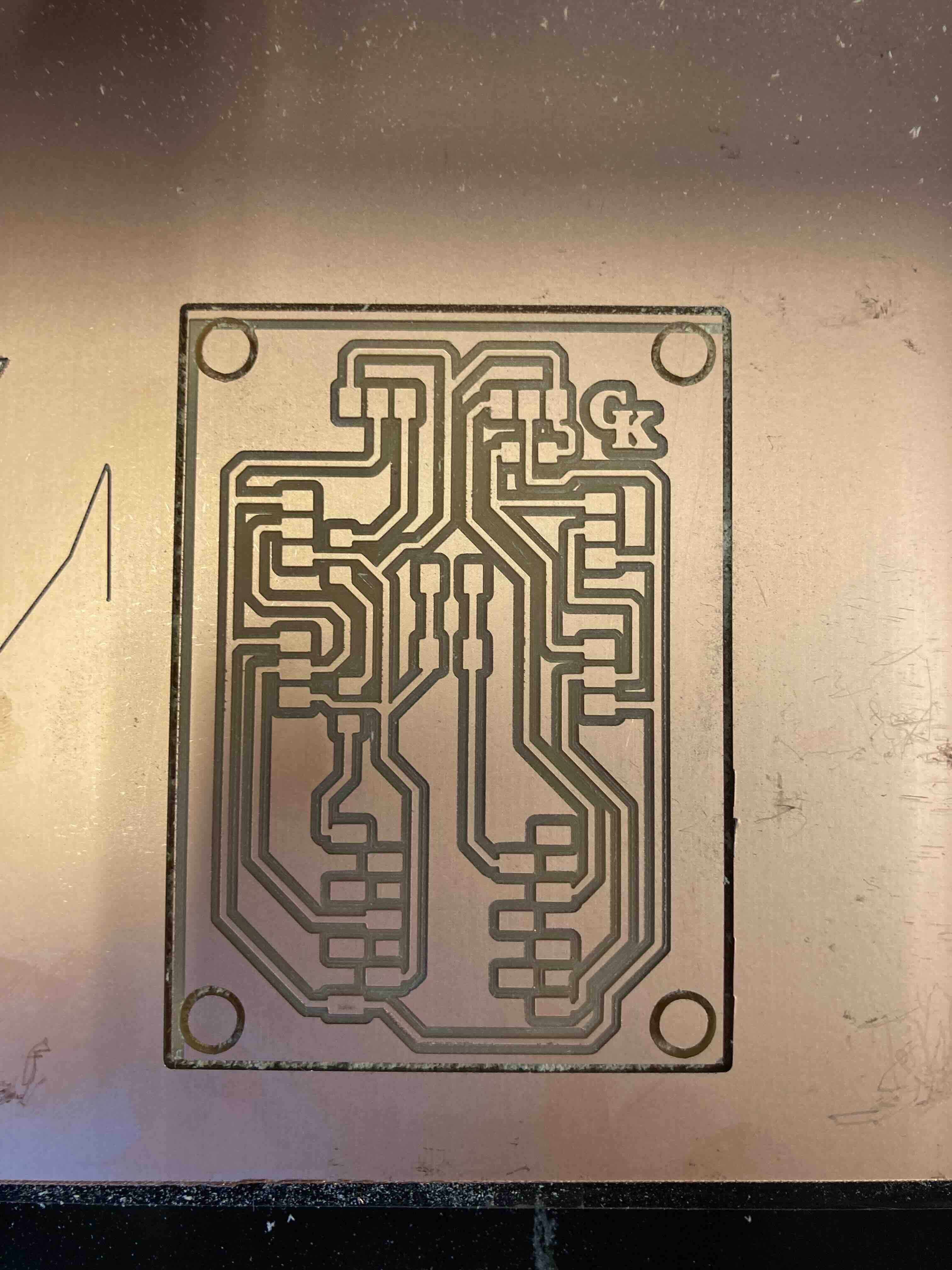
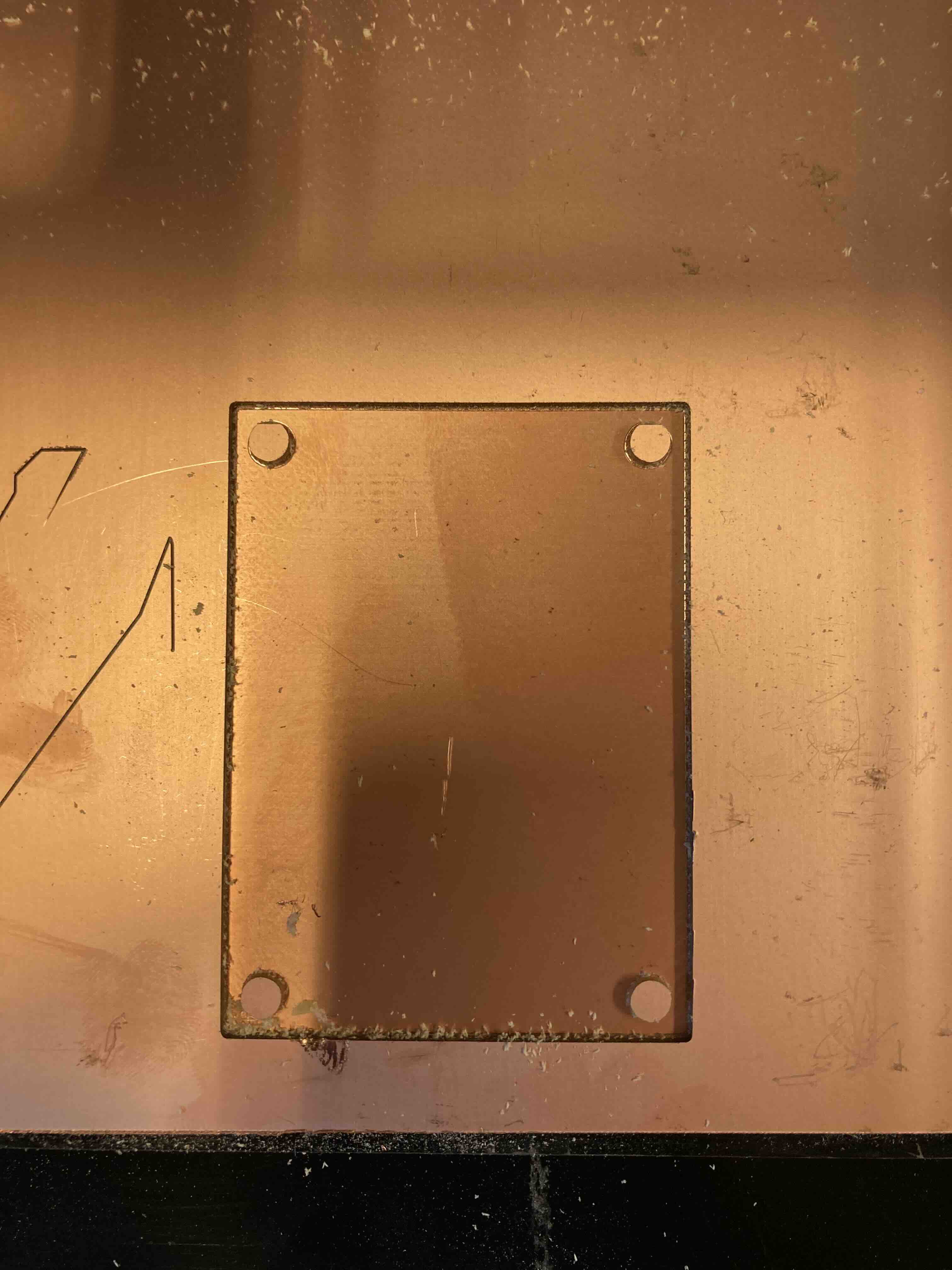
We start with removing the drilling(1/32) bit by using all that use tool that is usually attached to the roland modela mdx-20. It helps If you move the drill up so you have easier access to it. Remove that drilling to make space for the tracing drill(1/64). you start with putting the tracing drill(1/64). as far up as you can then you move the roland modela mdx-20 to the right position by lowering the drill down then you take that the tracing drill(1/64) bit make it touch the copper board unfashioned the tracing bit(1/64) and present when the roland modela mdx-20 is right.
Vacuum after roland modela mdx-20 is done.
Parts needed
| Name | Quantity | |
|---|---|---|
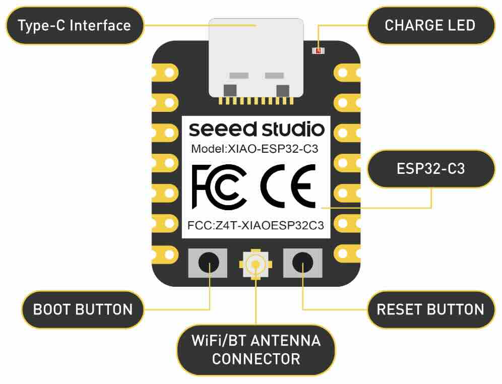
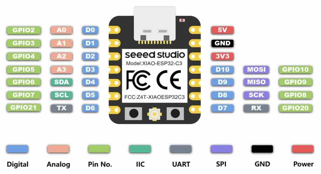
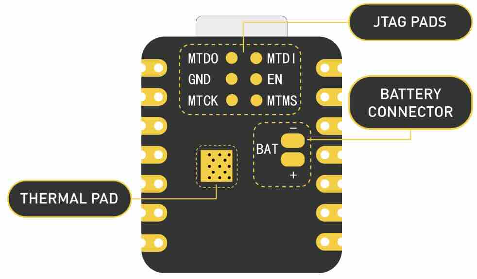
| Xiao ESP32C3 |
1x | |
| switch |
1x | |
| Resistor (0 ohm) |
3x | |
| Header Pin cnnector Female 1x3 |
6x | |
| Header Pin cnnector Female 1x7 |
2x | |
Soldering: Board
Assembled
Summary
This is an overview of the entire project. More information is under each of the project parts.