Machines, Programs and Tools
Mac computer, screen, IPhone, GitLab, HTML site, patience.
introduction
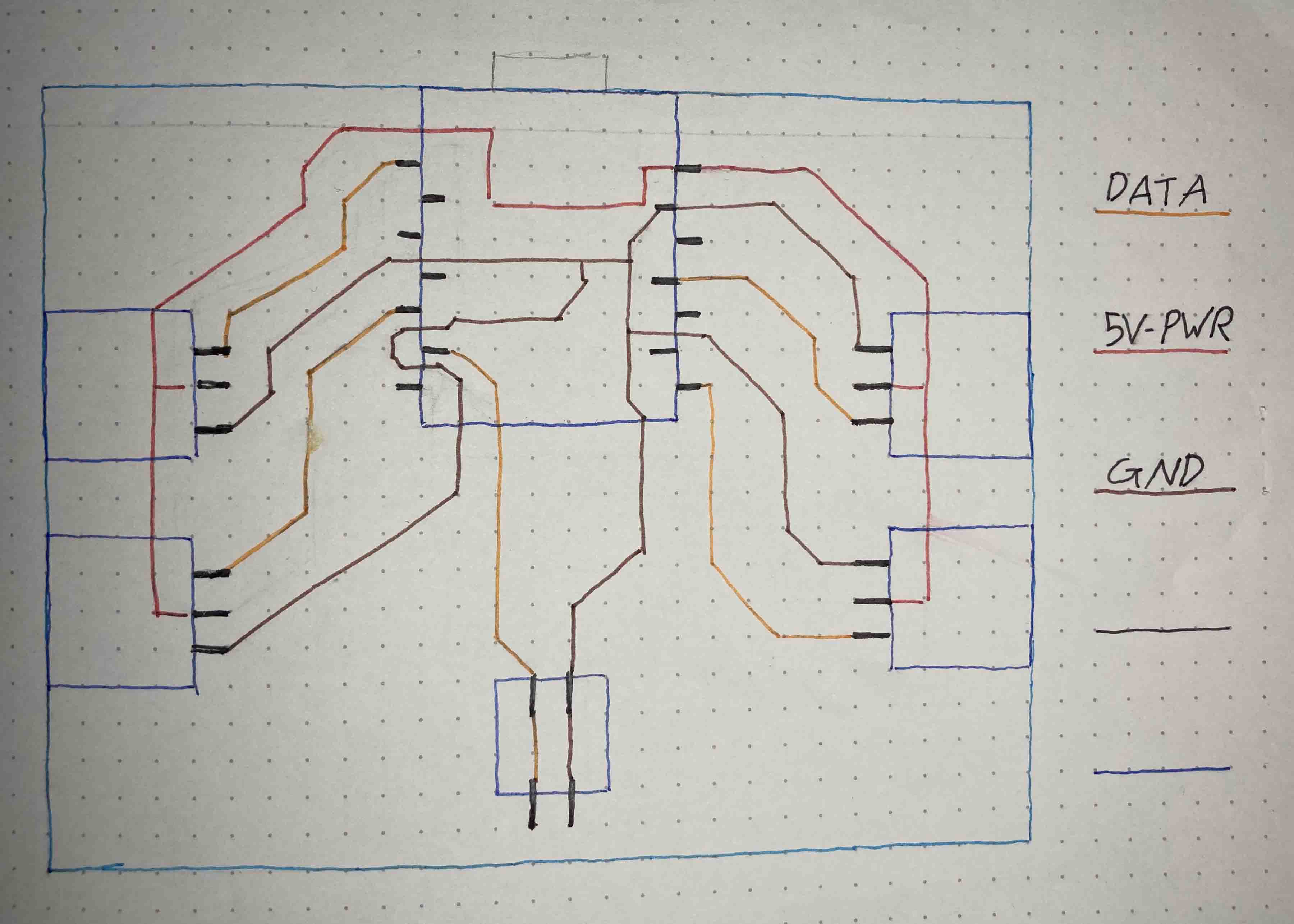
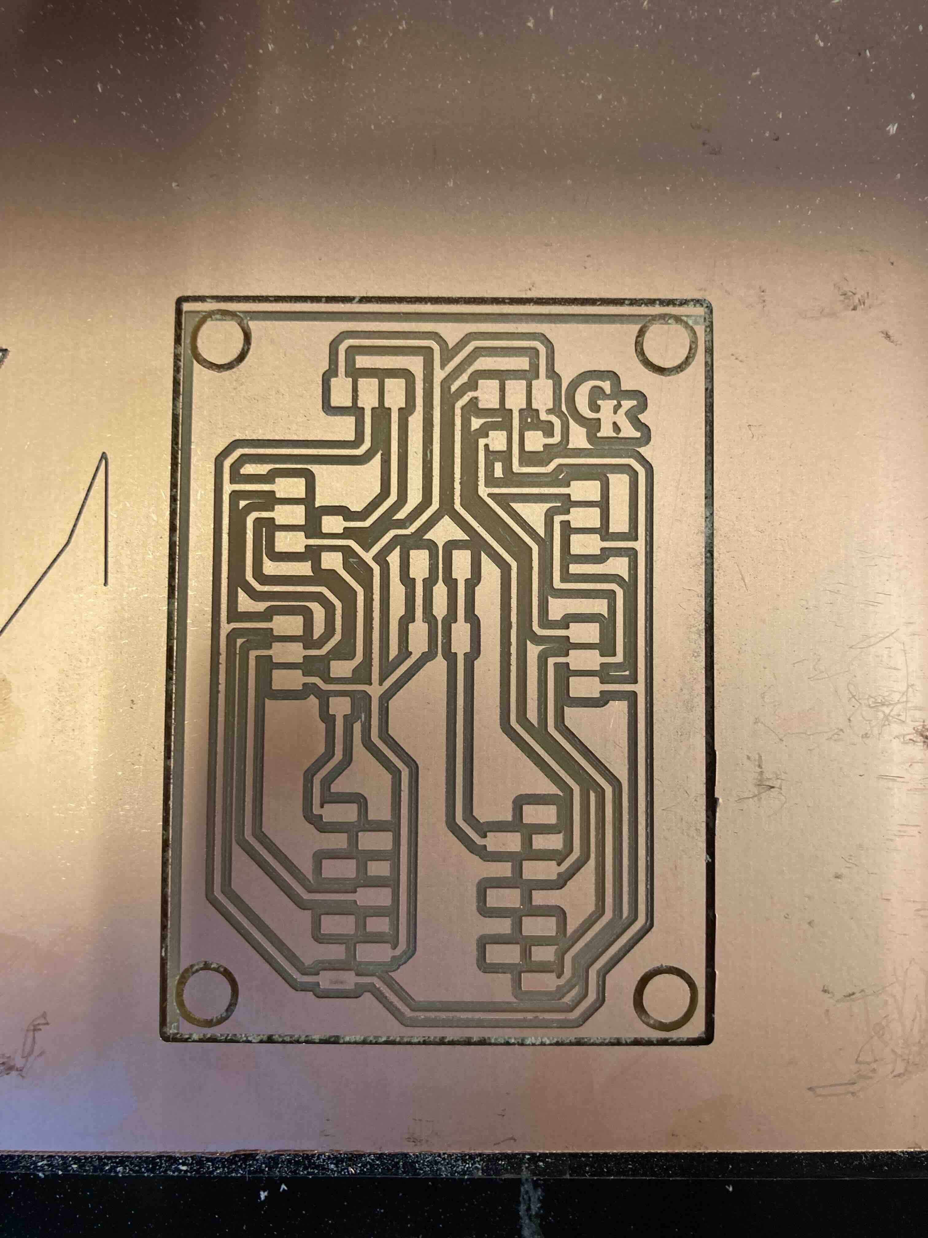
This is the PCB board part of the project. Initially designed it by hand for two servos and 2 light strips. Then decided to have 4 lightstrips on it.
Sketches

The first sketch for the PCB board. I did it by hand so I could see the different lines (data, power, GRD)
Projects
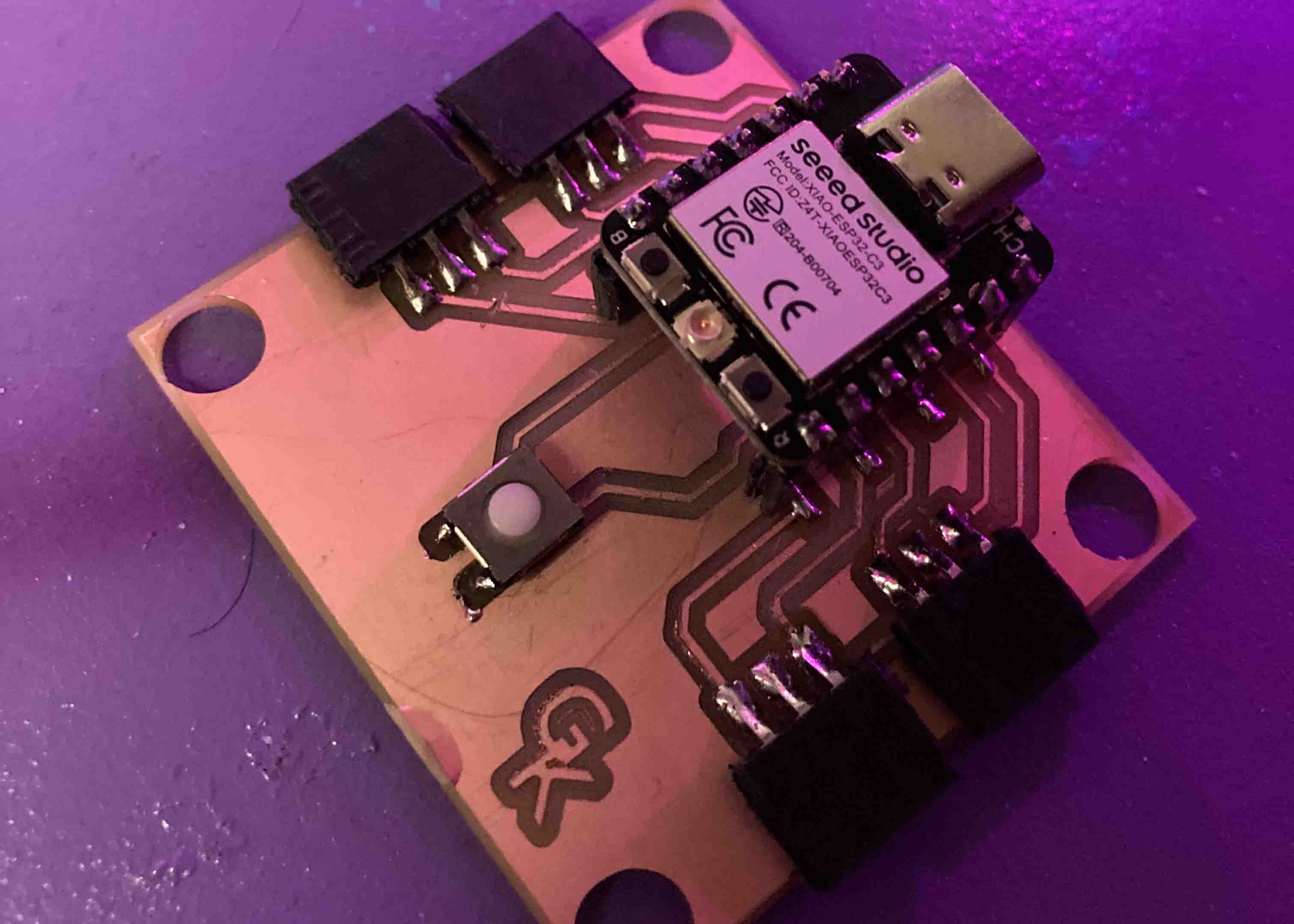
1st version of PCB
First version of the PCB plate for the final project. It worked but I had to manually cut the lines because they were too close together. So the first PCB board wasnt good enough.


Sketches
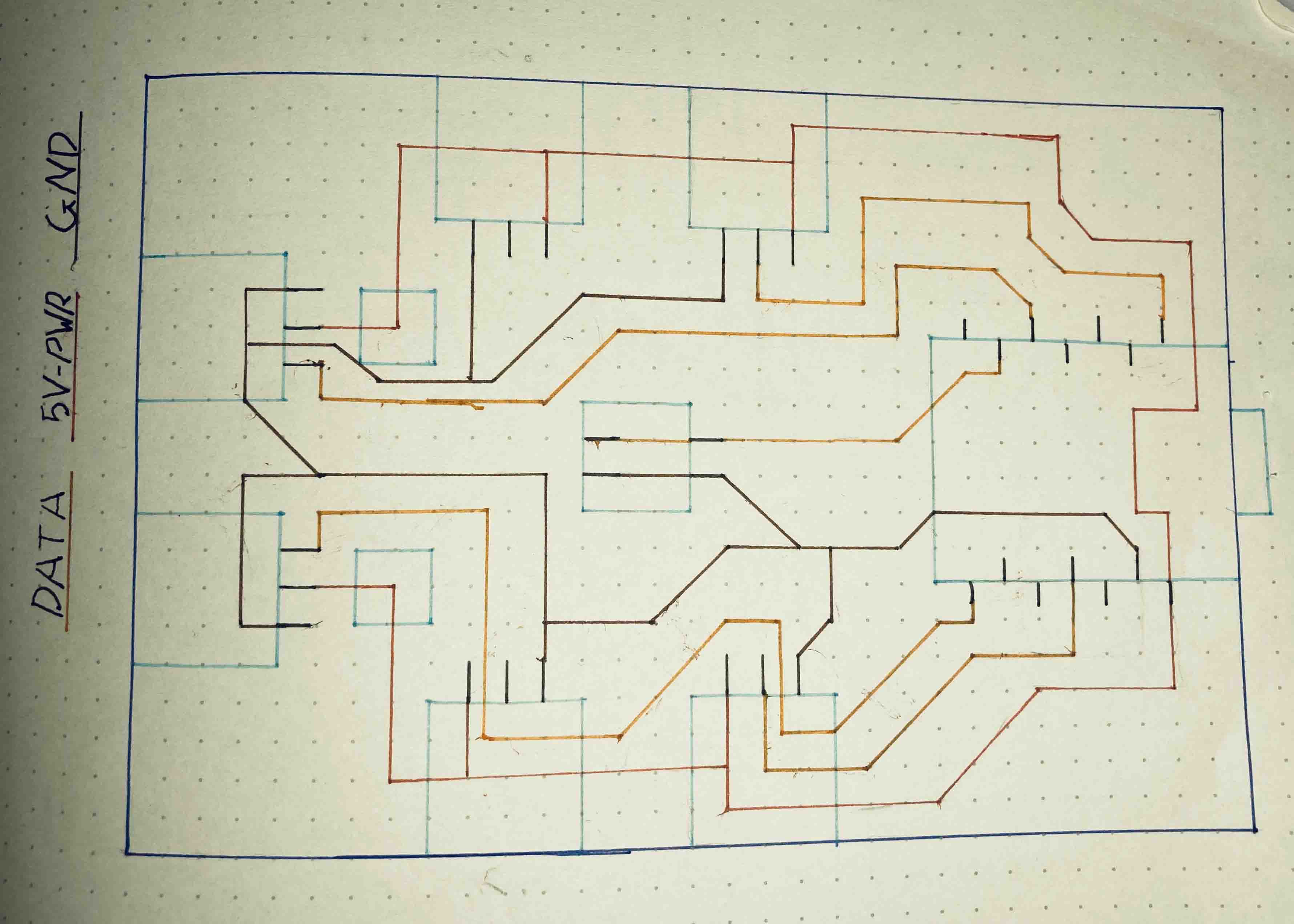
The second version had 4 light strips and I made room for conductures. I didnt end up needed them, and I fixed the problem with the first board.
KiCad: PCB Editor
2nd draft of PCB board.
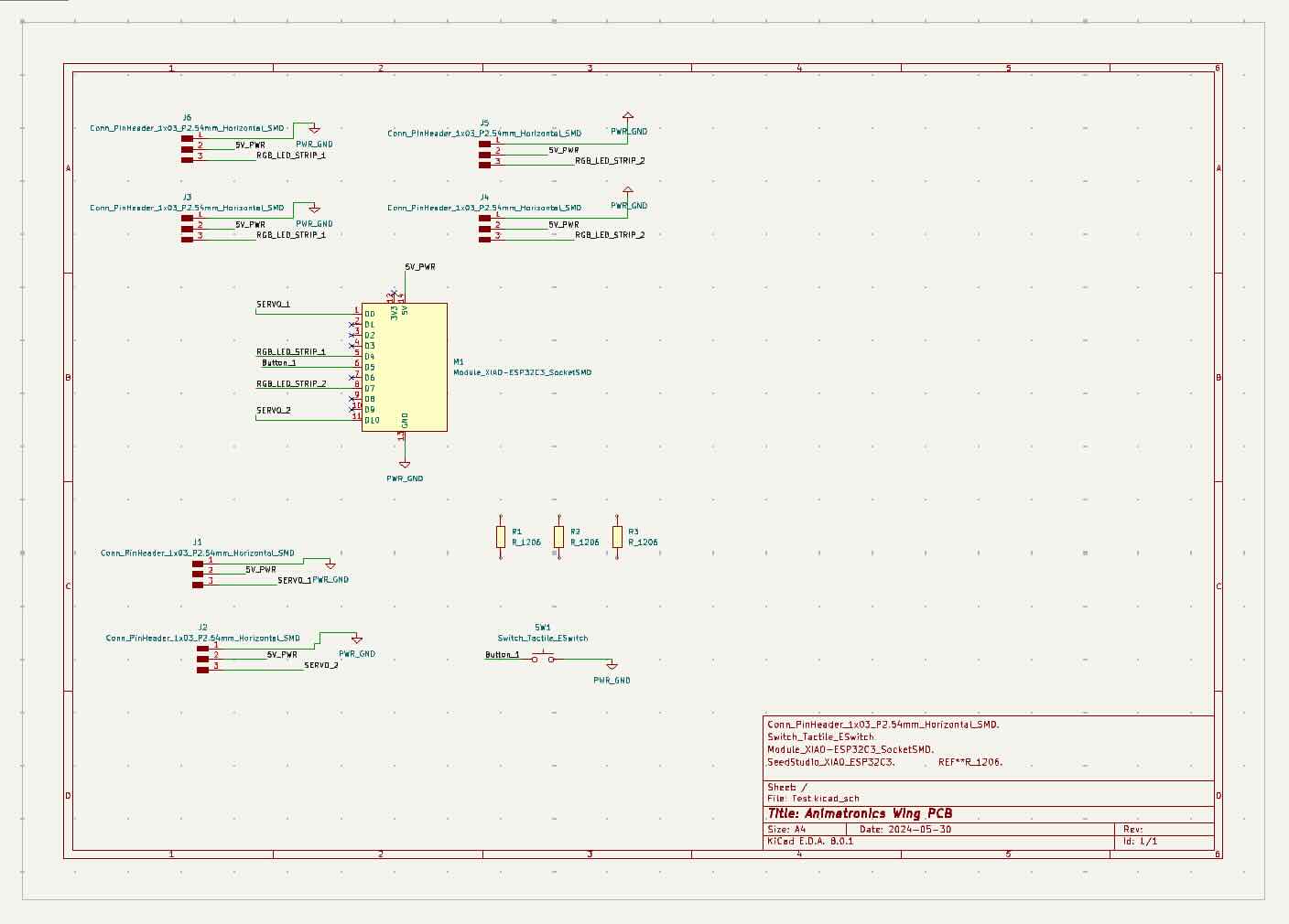
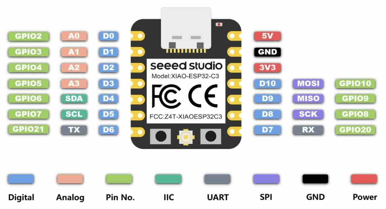
KiCad: Schematic editor
all the parts and placement of the electronics.
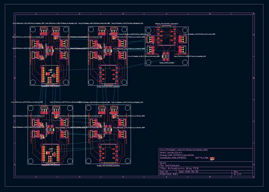
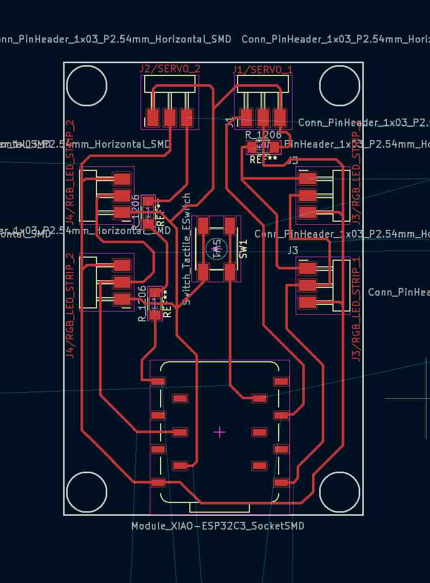
KiCad: PCB Editor
5 versions of the board that I made. the top row werent good enough and had errors in them.
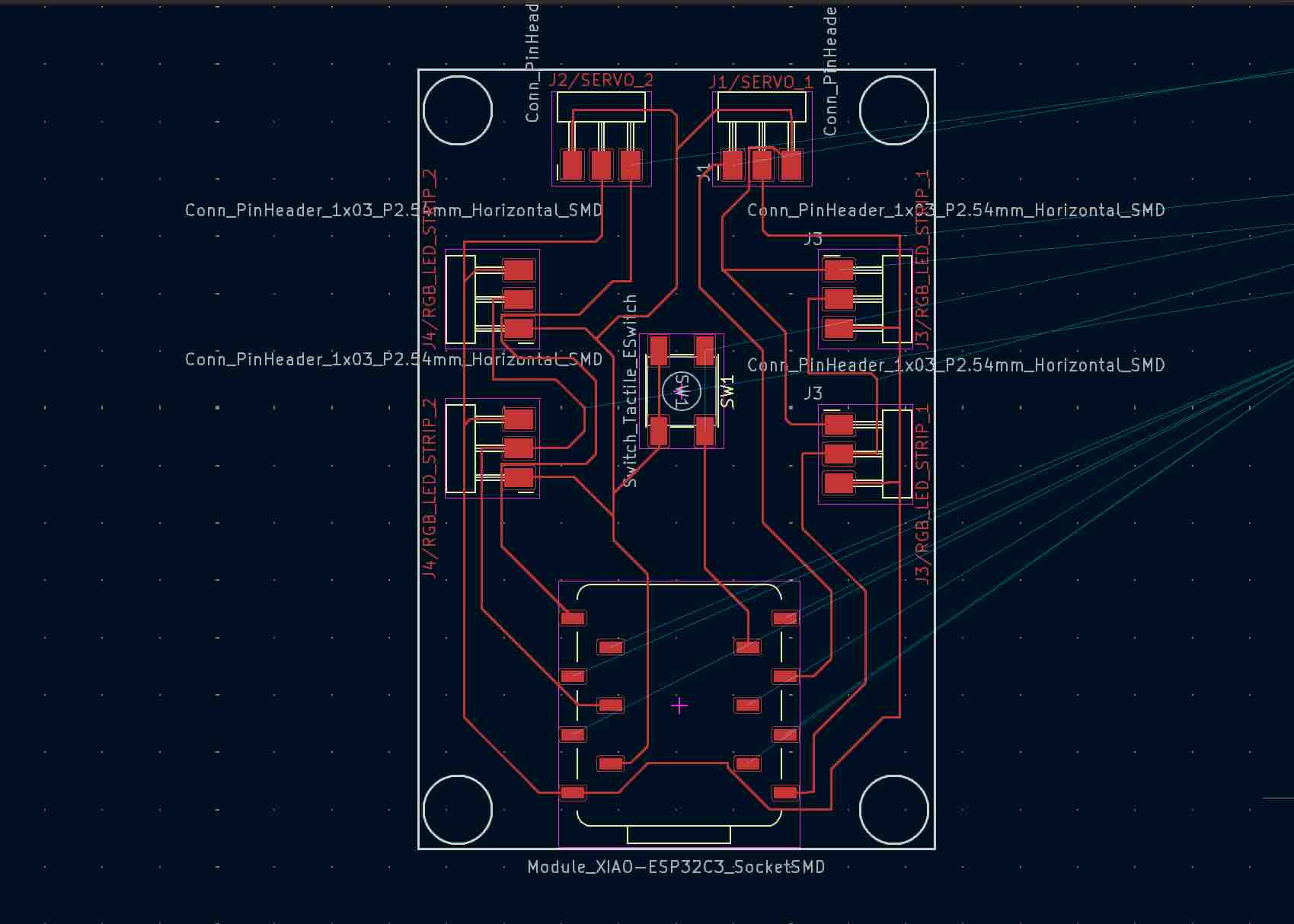
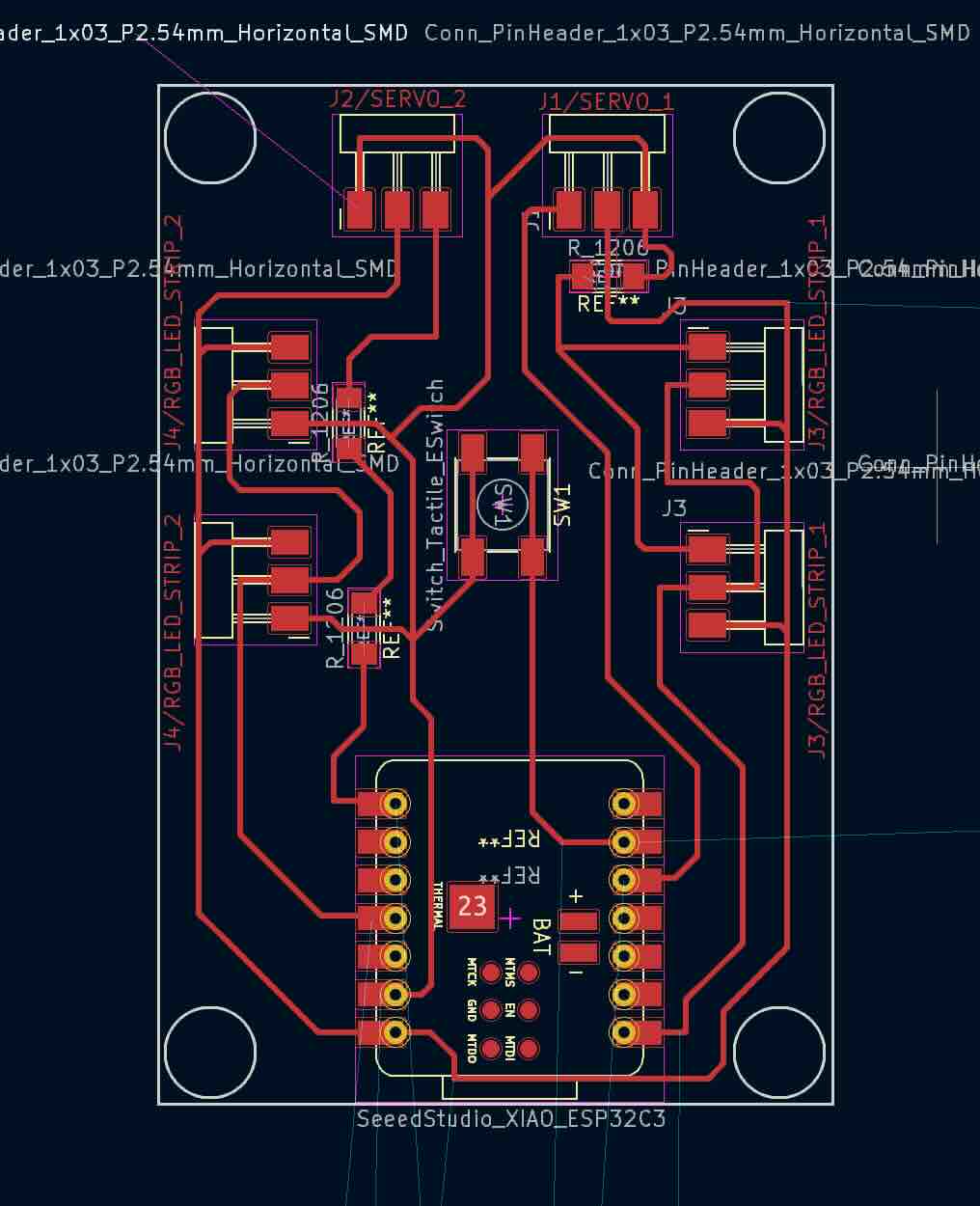
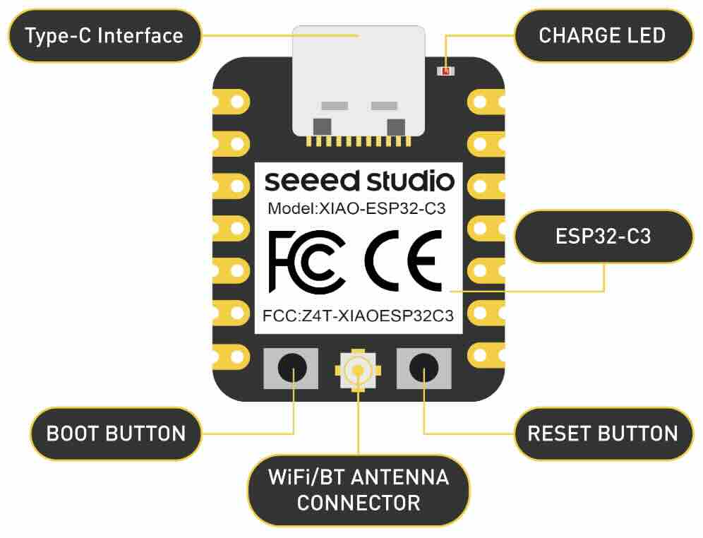
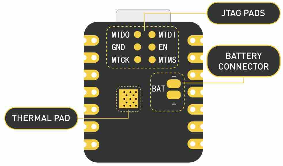
KiCad: PCB XIAO mount to board.
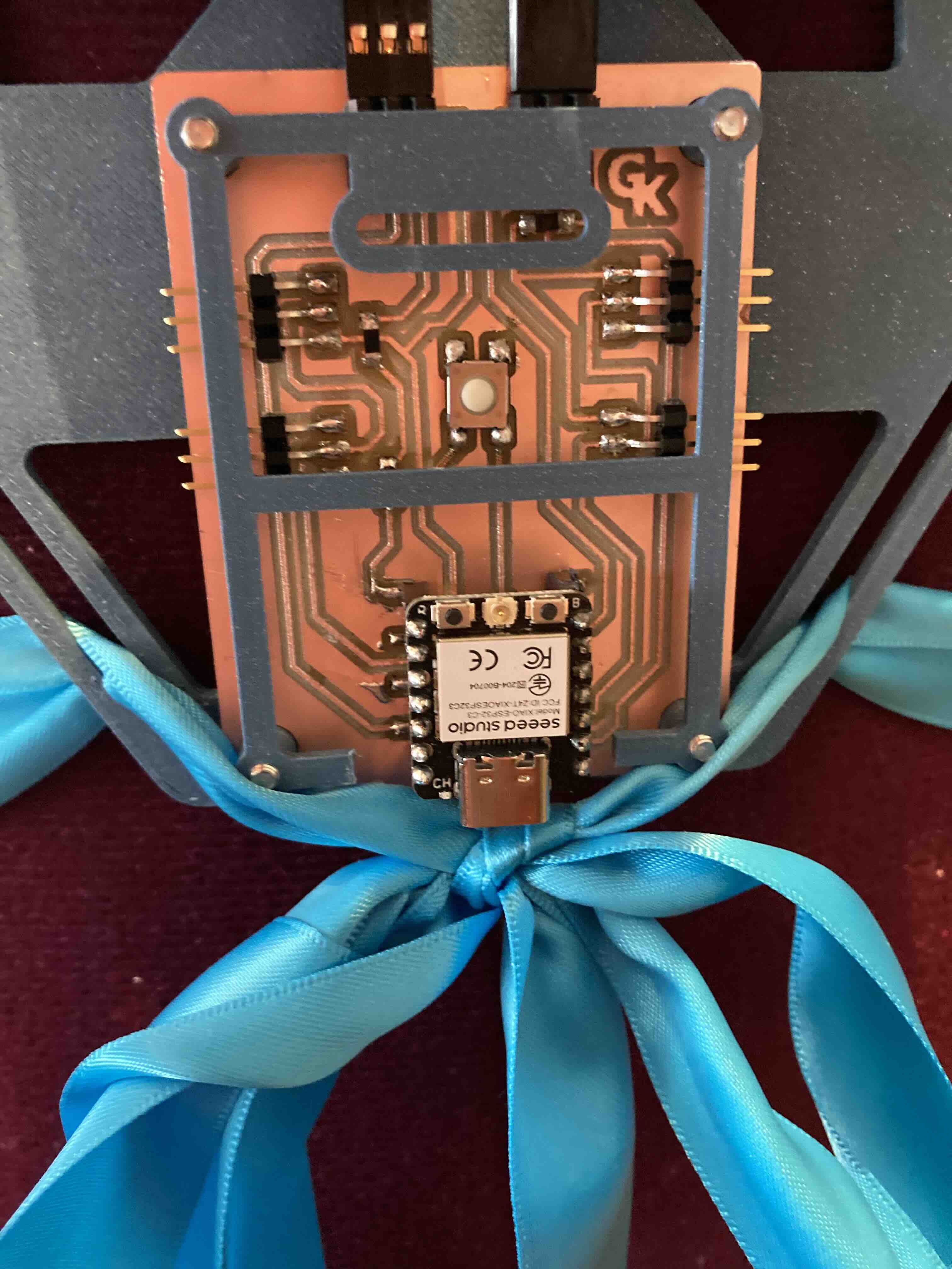
This version has the XIAO-ESP32-C3 soldered on the board.
KiCad: PCB XIAO with socket.
Used in final version. This version makes it possible to remove the Xiao-2BESP32-C3 if it burns out or becomes damaged.
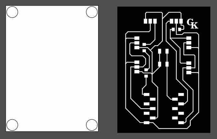
Inkscape
Inkscape/milling
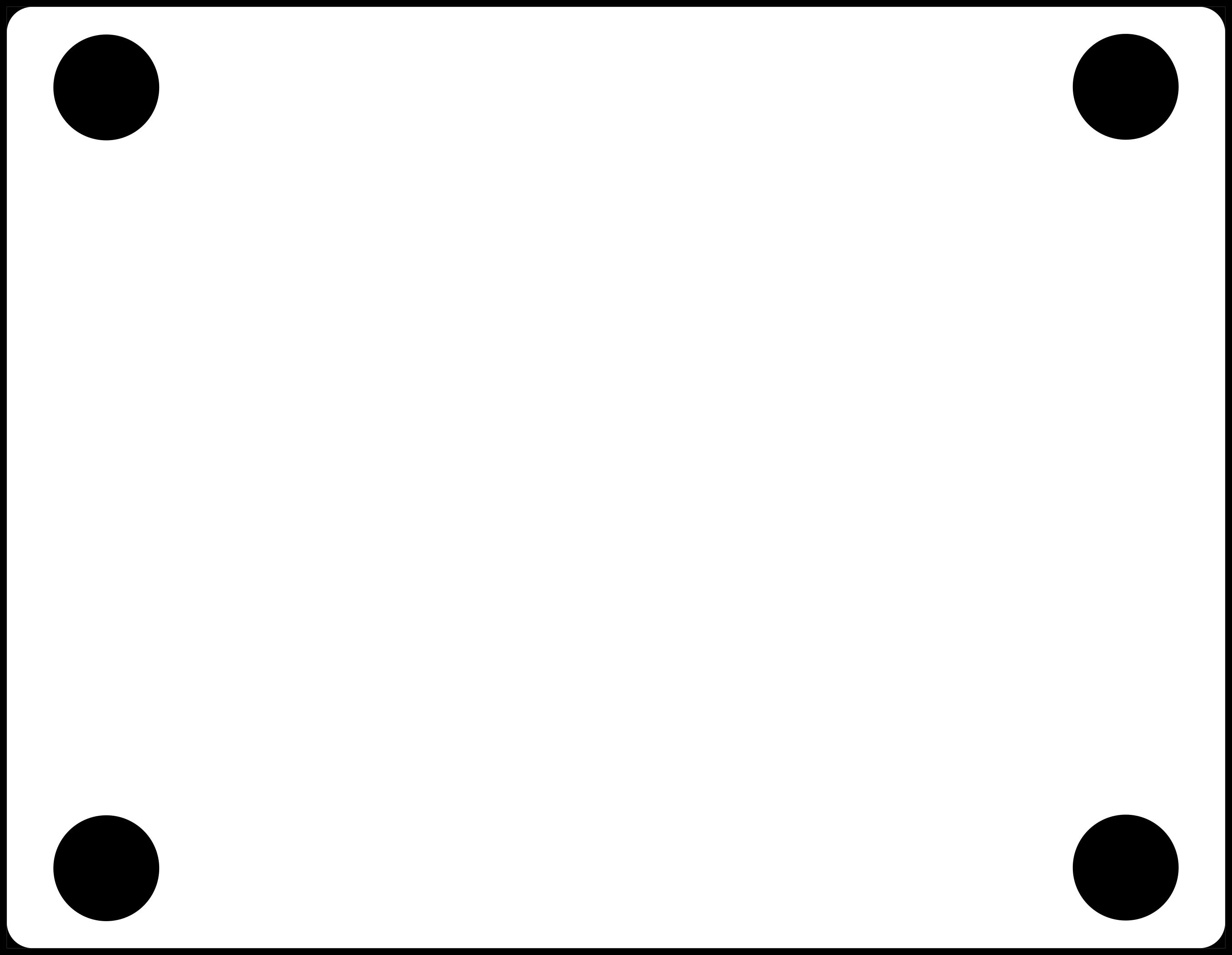
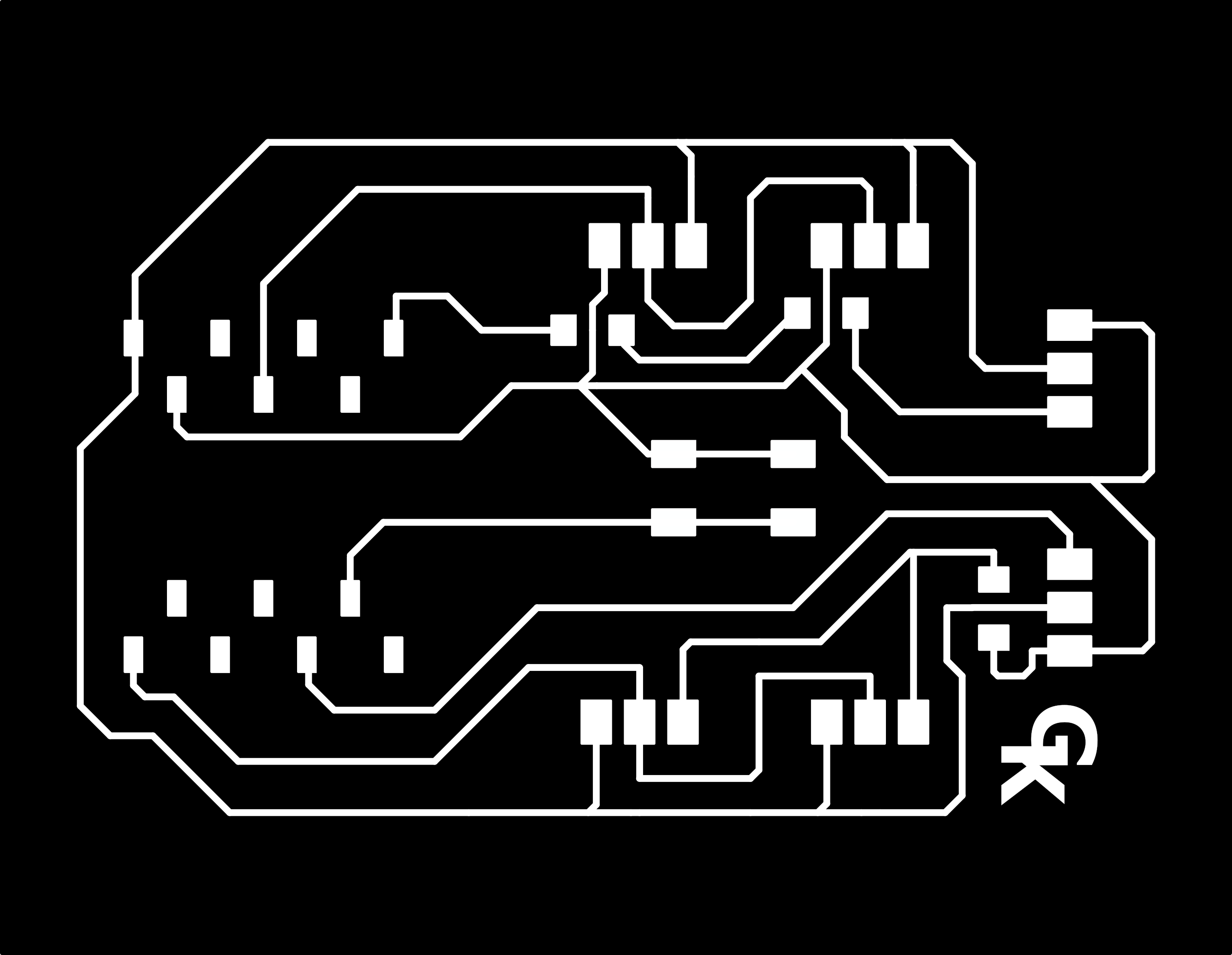
I started with downloading a file that and tell a pattern for the board. I opened the file and Incscape I made minor changes. I change the logo to my initials. Then I made a white box to put behind the file. When was done I exported the files made sure the DPI was set to 1000 then I moved the top layer to see only the white box exported the white box made sure that the DPI was set to 1000 I moved both files to my USB drive. I made the toolpath by working with a svg file in InkScape and saving that one as PNG fle. I then imported the file to fabmodule and make the G-Code. I pushed calculate on fabmodule to make the toolpath.
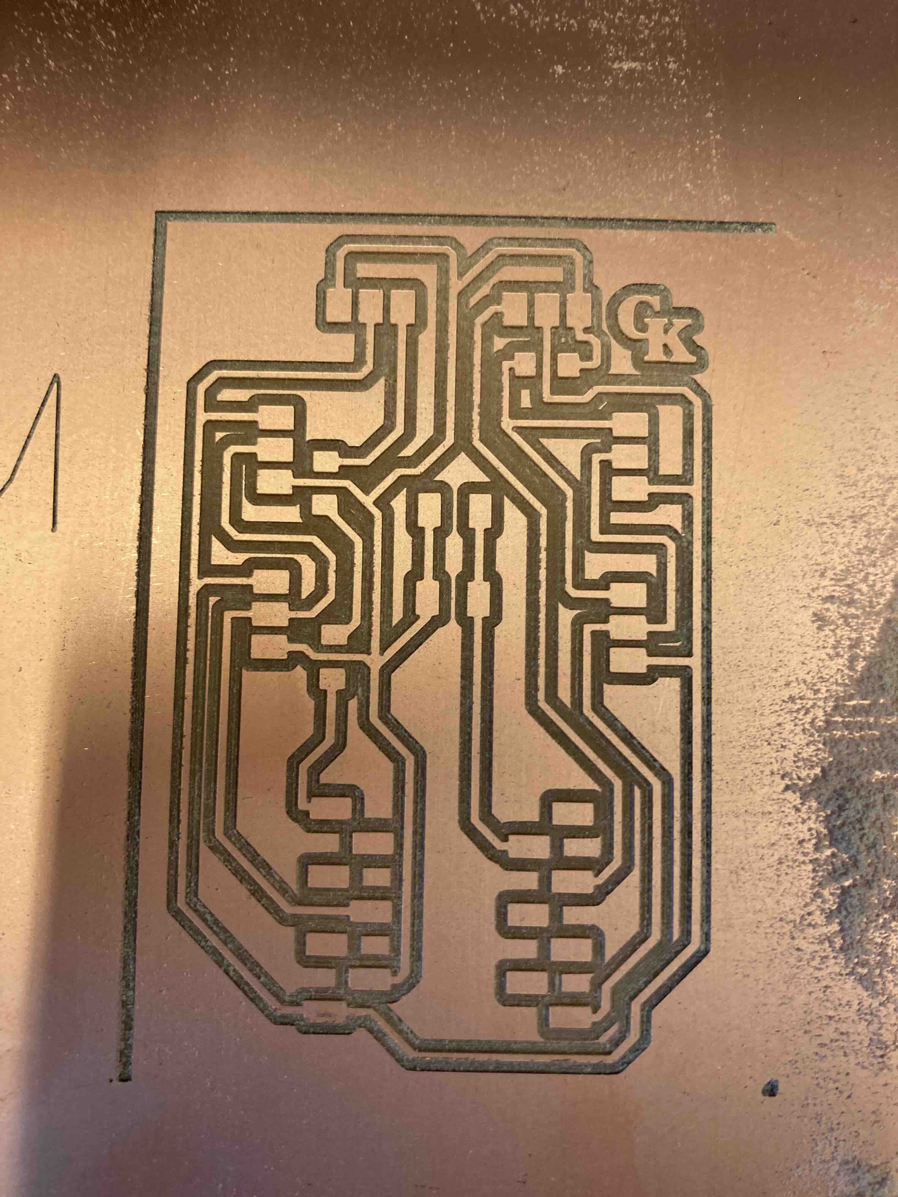
Milling
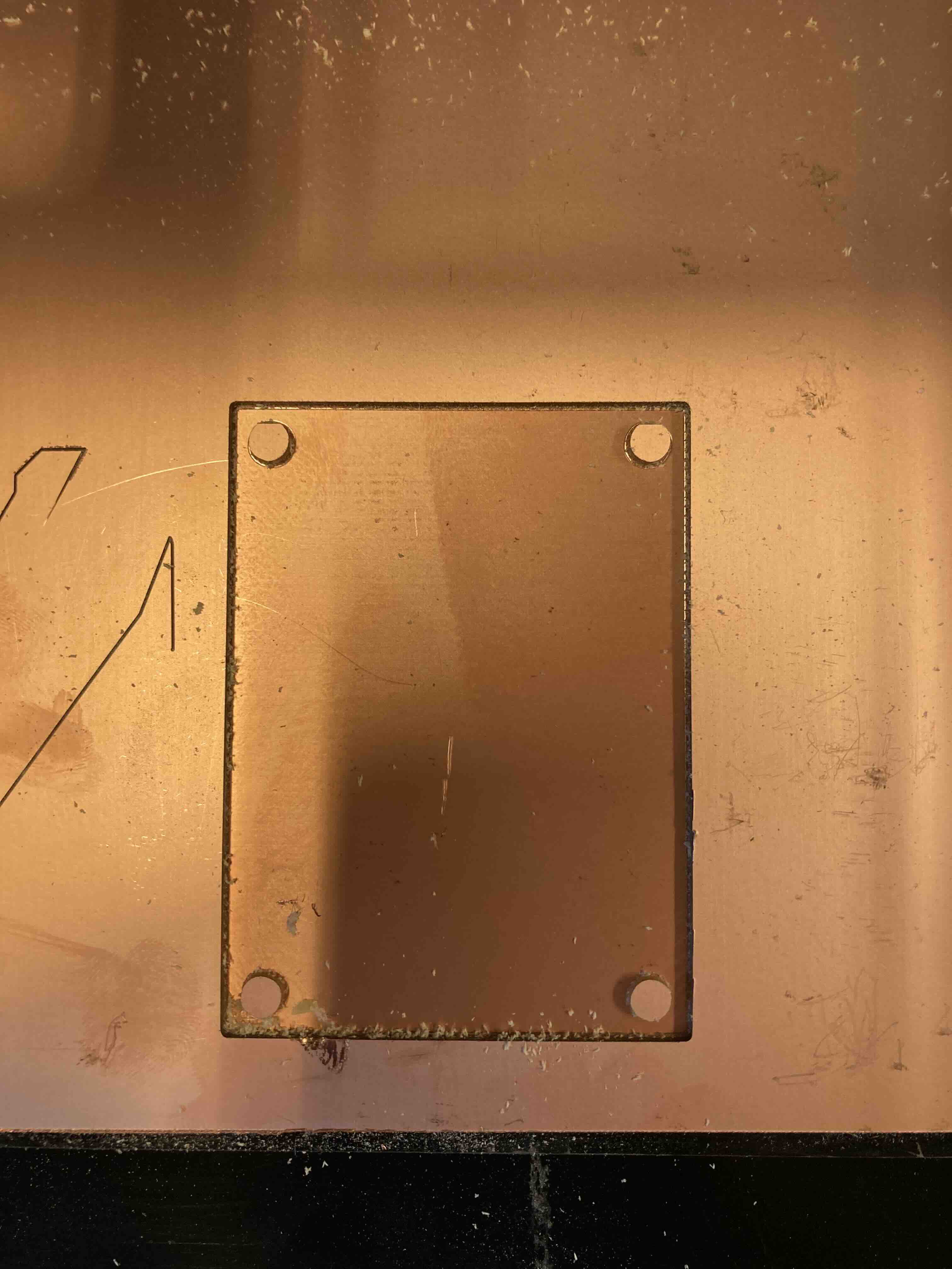
I got help with putting double sided tape on the back of the copper board the top double sided tape needed to lie next to other but not overlap. Remove the film of the double sided tape and attached the copper board to the copper board, that‘s attached to the roland modela mdx-20 to make sure the board doesn‘t warp. Spray the board with ropping alcohol and to clean the fingerprints.
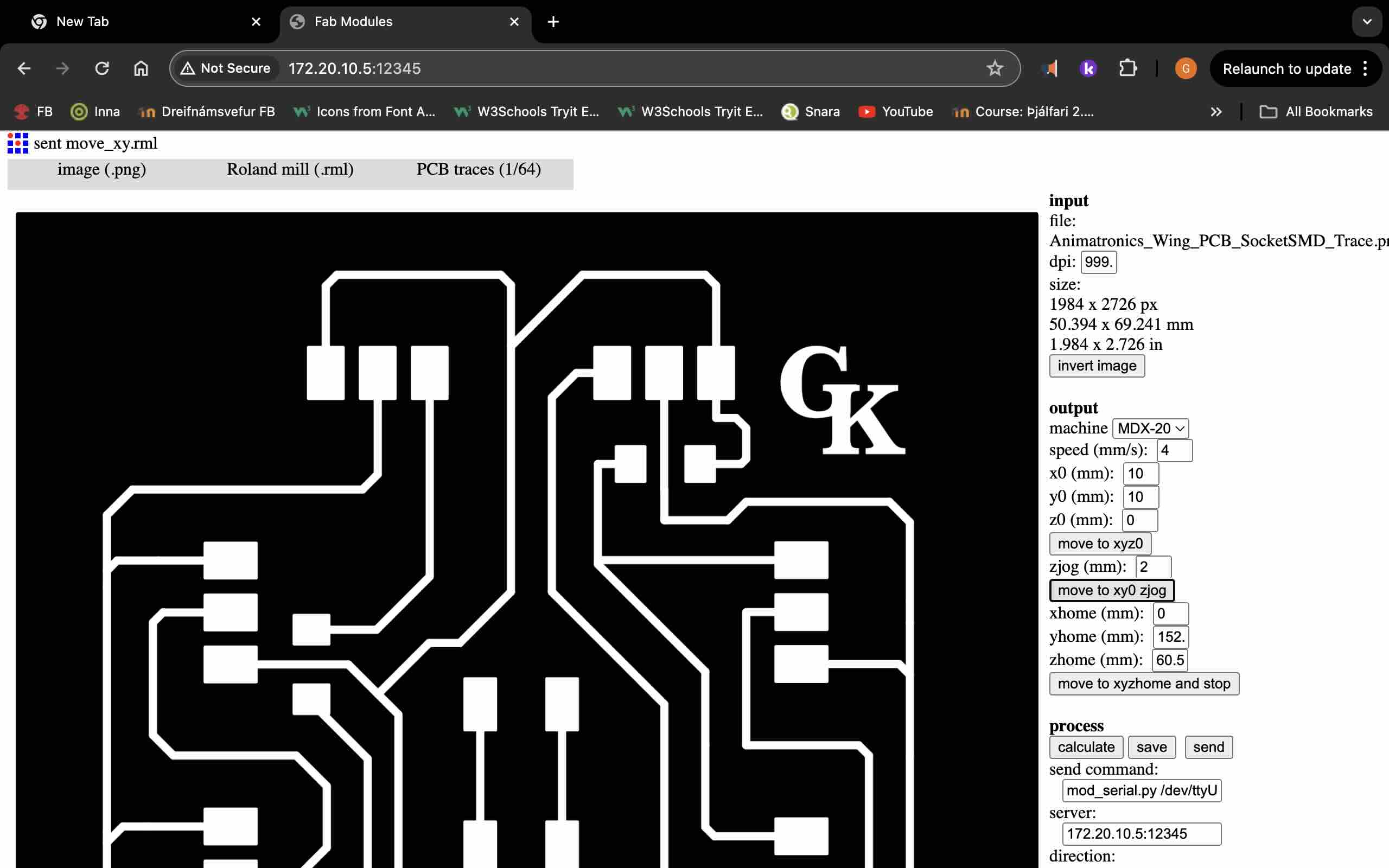
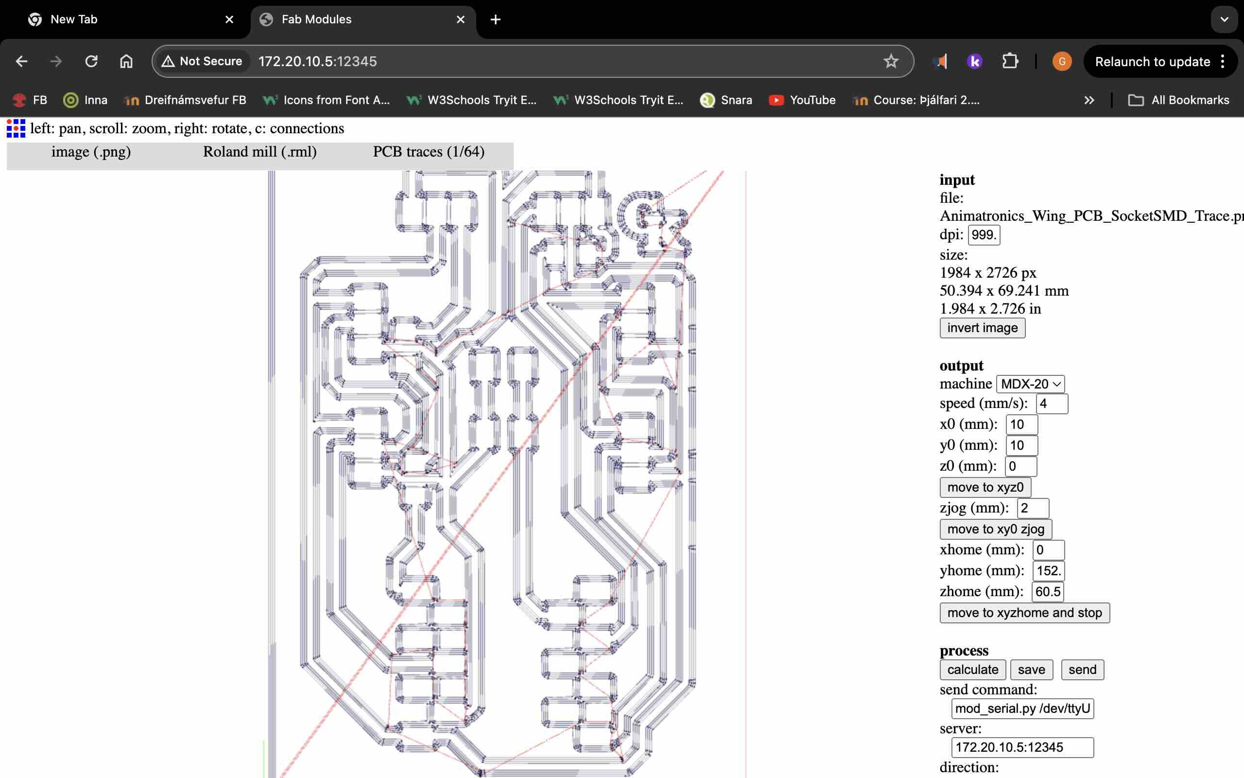
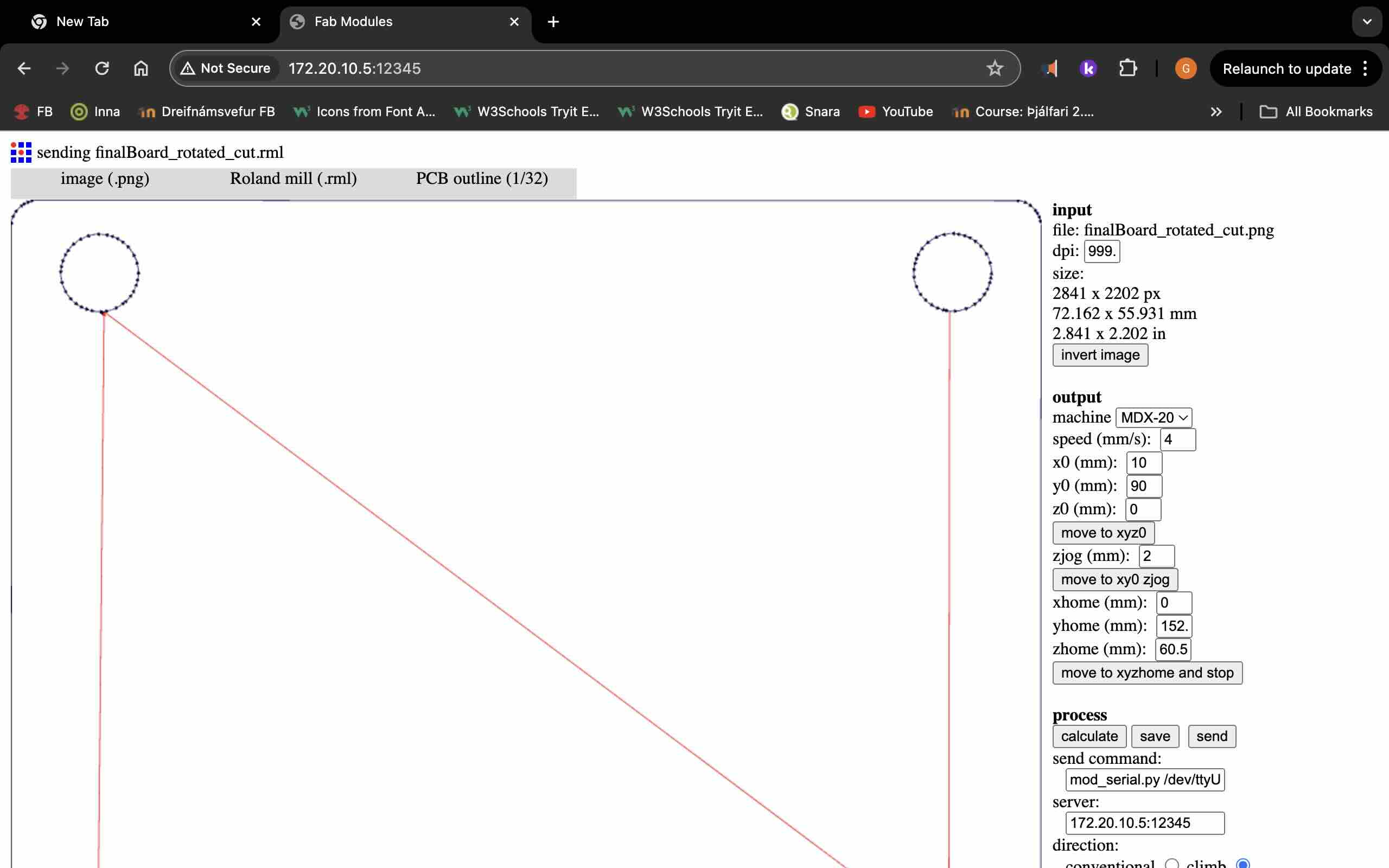
Input: you first set the board size (the dimensions) and DPI (desired resolution(Dots Per Inch)). Then invert the image. Output: Select the mashine (MDX-20, Adjust the milling speed), Configure XYZ home (the starting point), Move to home (Hit move to xyz0 to move to home, set x0 y0 z0. The move to xyz0 moves to home but keeps the milling at a safe distance from the board 2mm), Safe ZJog (for safety). Process: Here you need to change the server ip port to match the hosting server. Keep other settings as defult and unchanged (self explanatory). The calculate button creats the tool path. Final step: Hit send to begin the milling process, monitoring the mashine to ensure proper operations.
We start with removing the drilling(1/32) bit by using all that use tool that is usually attached to the roland modela mdx-20. It helps If you move the drill up so you have easier access to it. Remove that drilling to make space for the tracing drill(1/64). you start with putting the tracing drill(1/64). as far up as you can then you move the roland modela mdx-20 to the right position by lowering the drill down then you take that the tracing drill(1/64) bit make it touch the copper board unfashioned the tracing bit(1/64) and present when the roland modela mdx-20 is right.
Vacuum after roland modela mdx-20 is done.
Parts
| Name | Quantity | |
|---|---|---|
| Xiao ESP32C3 |
1x | |
| switch |
1x | |
| Resistor (0 ohm) |
3x | |
| Header Pin cnnector Female 1x3 |
6x | |
| Header Pin cnnector Female 1x7 |
2x | |
Soldering: Board
Summary
The PCB board went through several changes. I made that one from scratch so some problems were bound to happen. First edition I put the circuits too close together so they connected. I ended up with the rule of thumb more is better in space between them. I also changed my mind and wanted 4 LED strips. First time I put female connectors instead of male but that board didnt work anyway so I didnt have to solder them out and change them. The final version works great and fits onto the backplate. In the end I did 5 versions of the board before landing on the 5th and final PCB board.