Embedded Programming
Project description
Group Assignment
Bowse through the data sheet for your microcontroller compare the performance and development workfolws for other architectures.
Individual Assignment
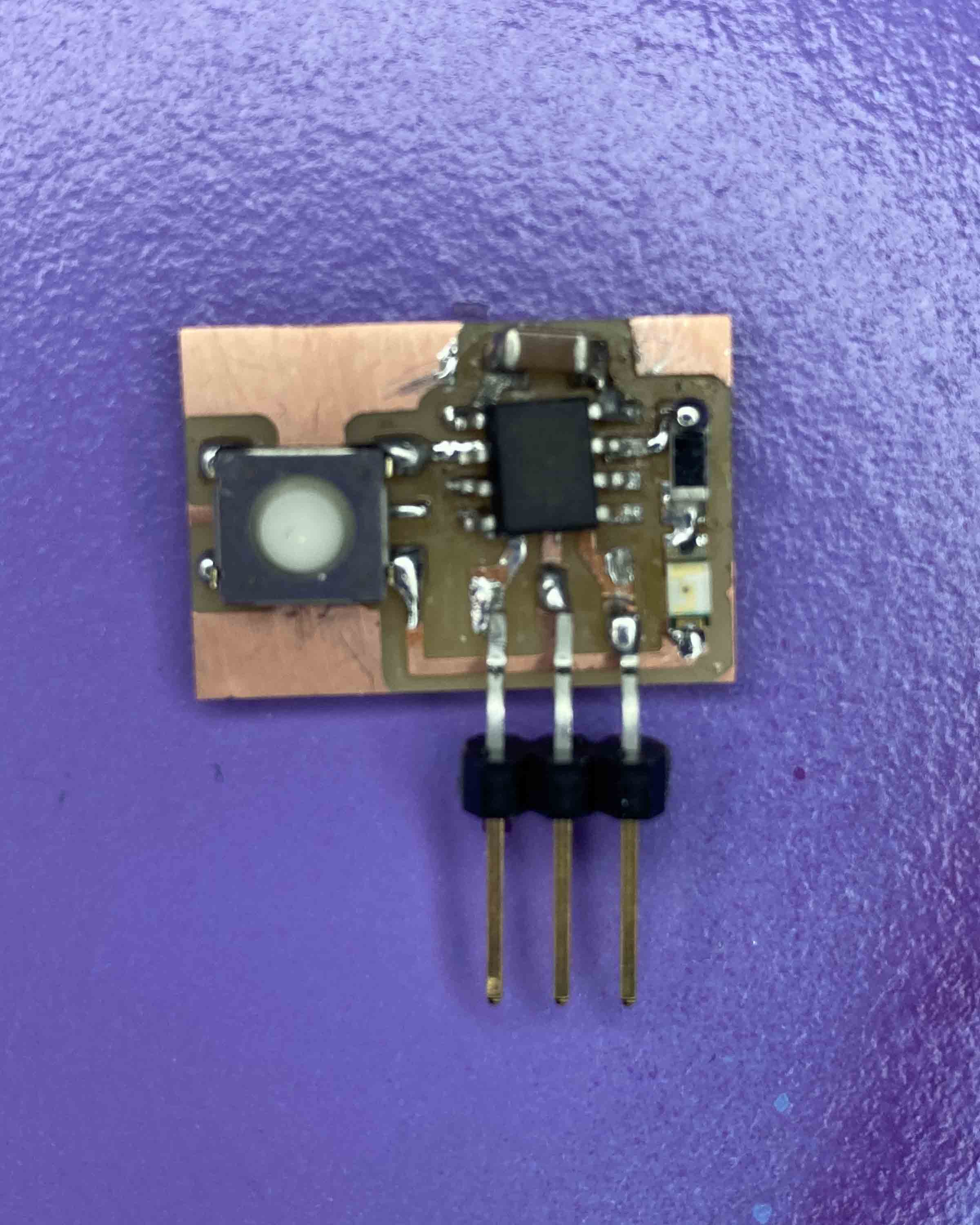
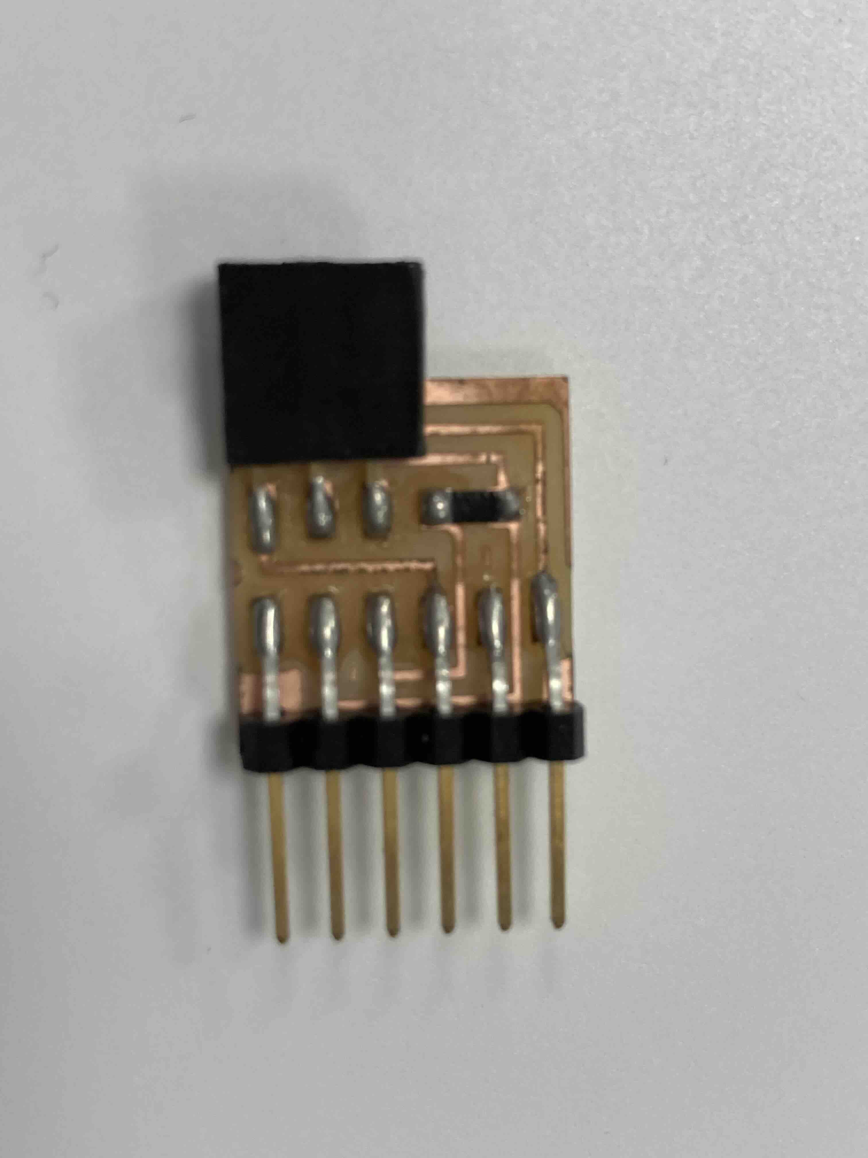
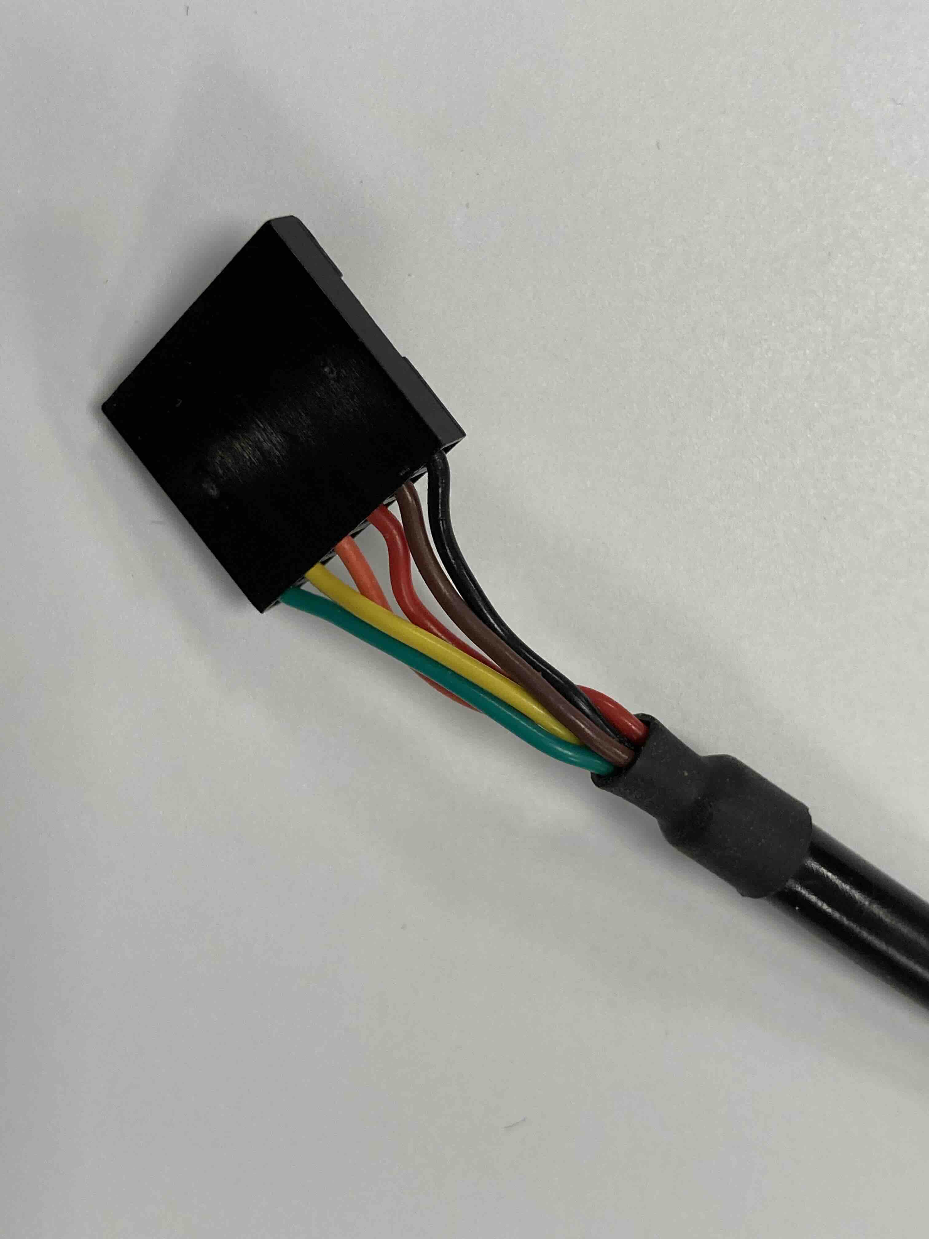
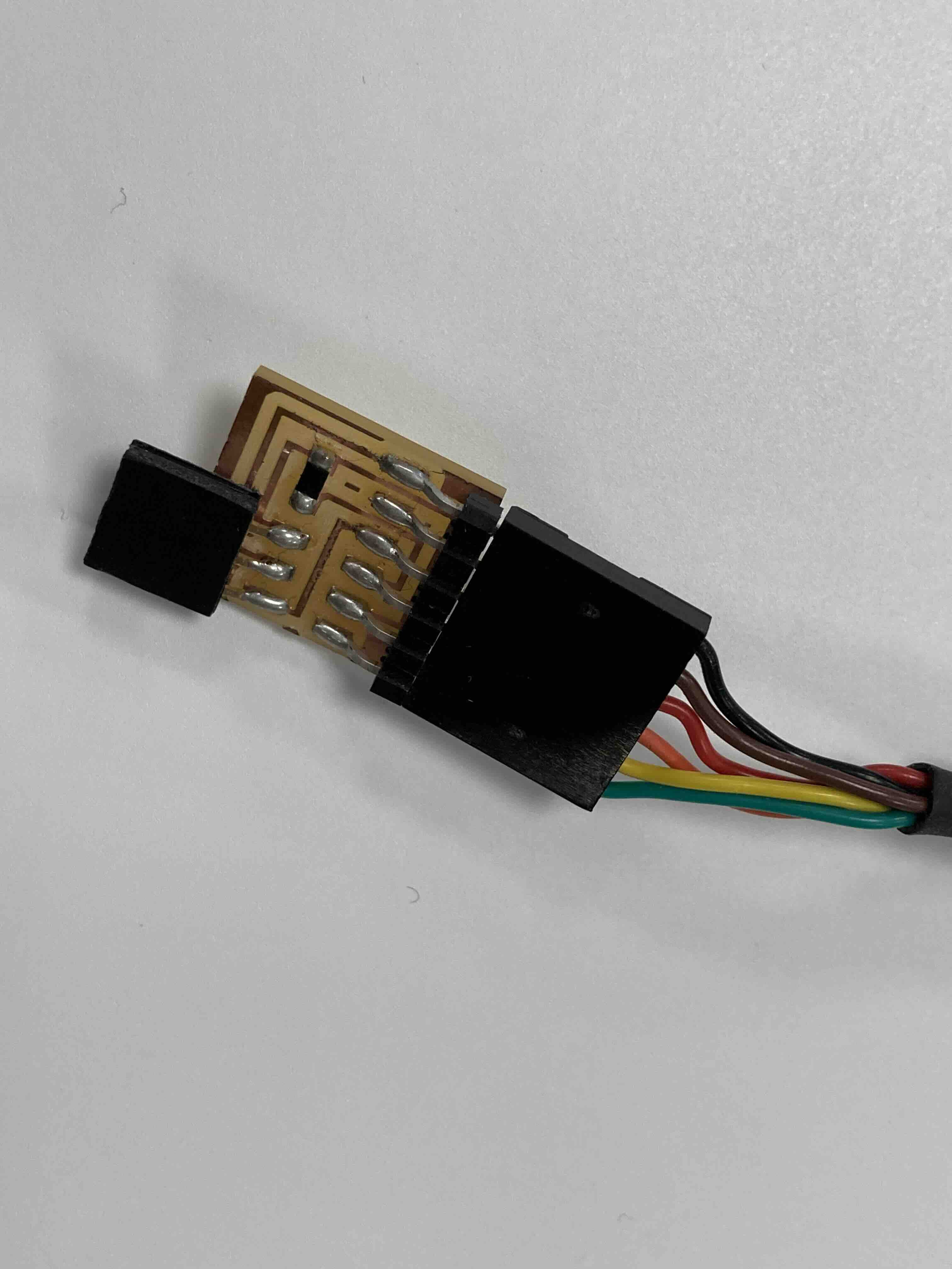
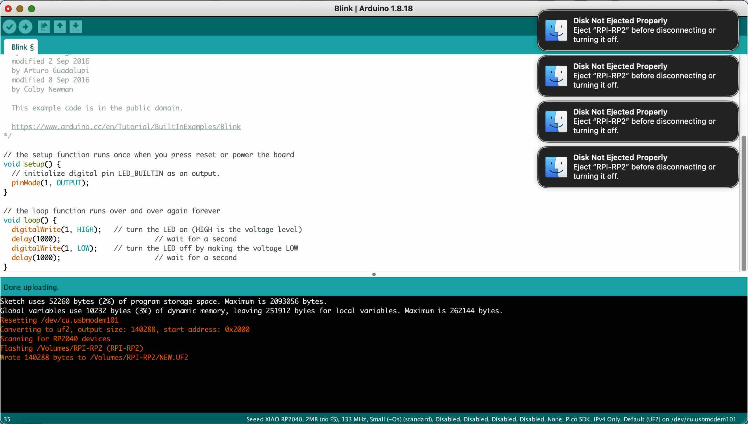
Write a program for a microcontroller development board that you made, to interact (with local input &/or output devices) and communicate (with remote Wired or Wireless deices).
- Extra credit: Use different languages &/or development environment.
- Extra credit: Connect external components to the board.