7. Electronics Design
This week will be a dive into exciting but a bit unfamiliar waters. I’ve tinkered a bit with electronics, I’m more comfortable with low voltage DC than high voltage AC, so thats good!
This weeks goals:
-
Try out the labs test equipment
-
Observe a microcontroller in action
-
Experiment with electronics design software (EDS)
-
Remake a circuit, such as the
echo hello-world-
Add a button to the circuit
-
Add a LED to the circuit
-
Add a resistor to the circuit
-
Try to make the shape or form interesting
-
Try to make the circuit work!
-
The lab’s equipment
EspoTek Labrador
In the lab, we have a few different pieces of testing equipment, such as:
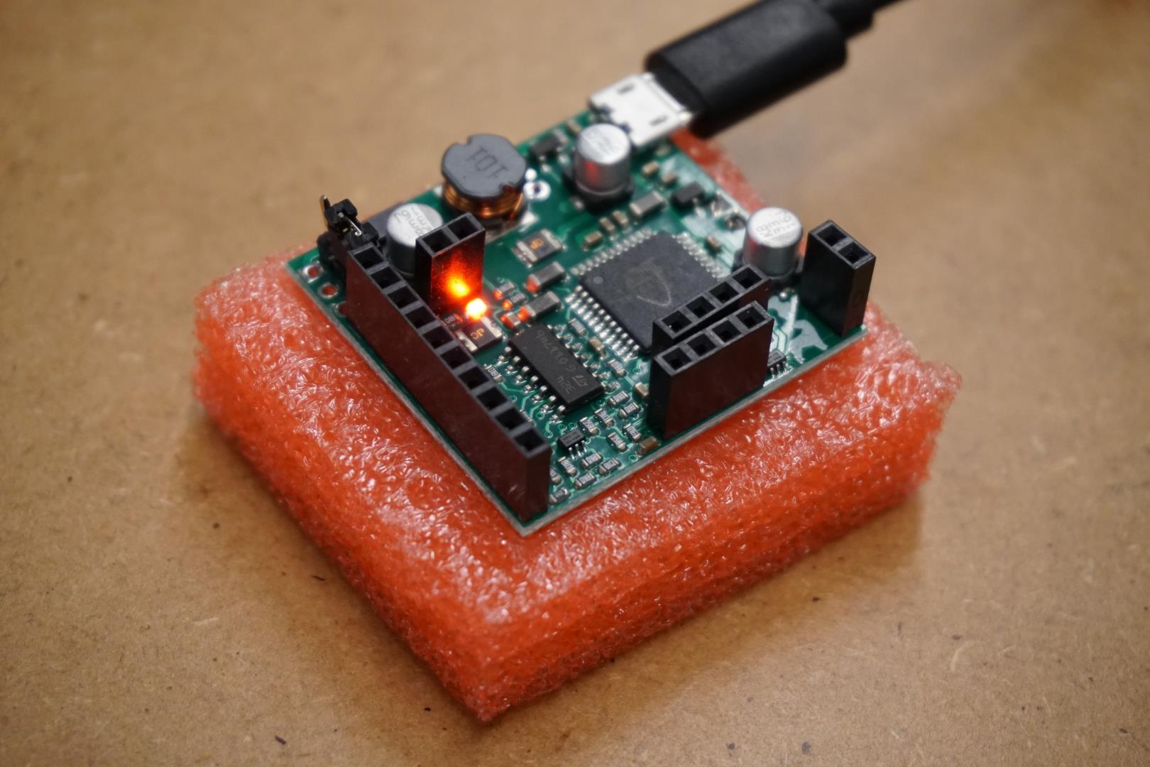
We do not have a logic analyzer, but fortunately a few weeks back I was browsing hacker news and found this piece of hardware. This tiny piece of kit seems to combine all these things into one! I ordered a couple of them and they arrived just in time for the Academy!
Now, before I’ve used multimeters, power supplies and even oscilloscopes a bit, but never before I’ve used a logic analyzer. So this week is the perfect opportunity to try the new thing out. I believe that if you learn how to use it and interpret the data, this board has a huge testing-capabilities per monetary item.
I installed the software on both Windows and Linux, and I’ve been able to use it on both.
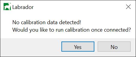
Once I started the program and connected the board to my computer, it prompted my calibrate the machine. Using pinout diagram from sites documentation, I followed the steps and it worked!
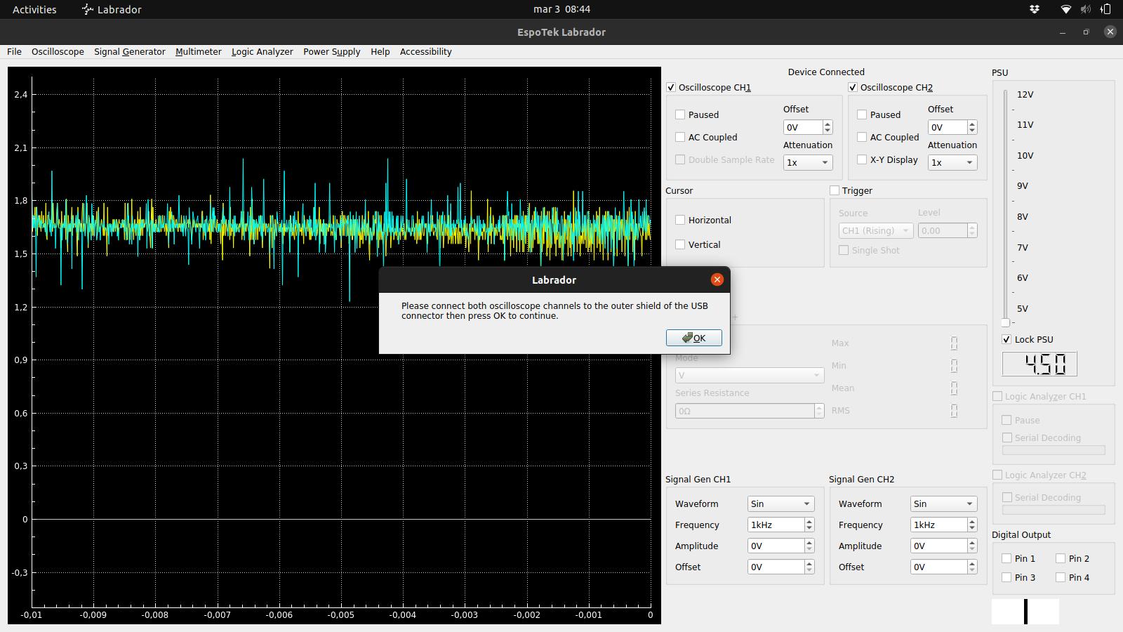
Here the data is about 1.6v with nothing connected.
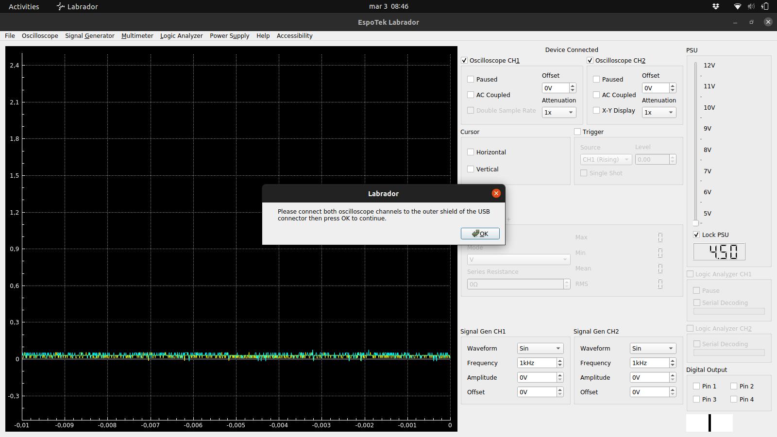
This drops the reading to 0v, and the noise is gone.
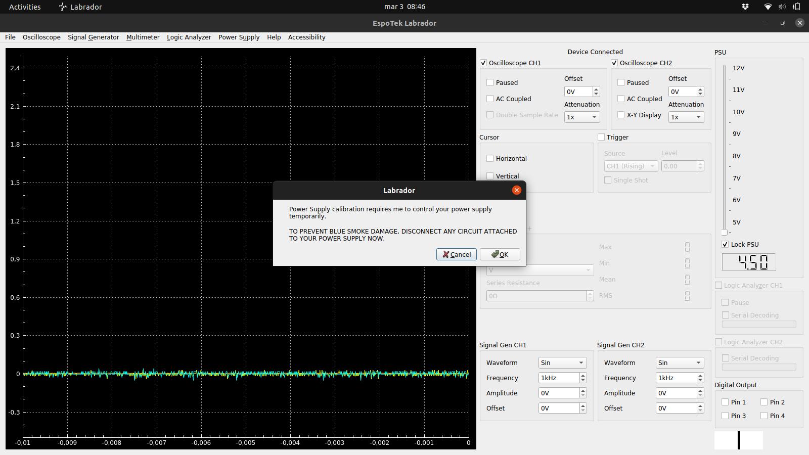
There was no blue smoke, everything’s good!
So I messed around with the board a bit. I measured the output of the built in power supply with the oscilliscope and the multimeter. When I set the PSU to 5v, both measured ~4.9v.
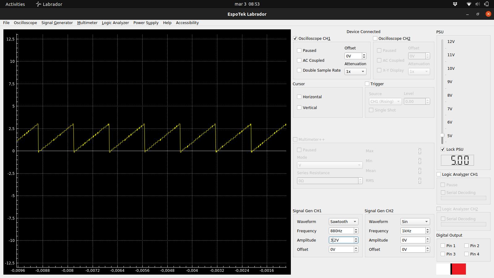
Next thing I did was to test the signal generator, which is pretty cool.
Trying EspoTek Labrador with Arduino Nano
Since I had not yet made a echo-hello-board, but I was excited to test it out I found a unused Arduino Nano in the lab and wrote this to test it out:
#include <Arduino.h>

void setup() {
  // Init serial
  Serial.begin(9600);

  // analog in pin
  pinMode(A0, INPUT);
}

void loop() {
  // read from analog in pin
  int analogValue = analogRead(A0);
  delay(400);

  if (analogValue > 500) {
    Serial.print("High value: ");
    Serial.println(analogValue);
  } else {
    Serial.print("Low value ");
    Serial.println(analogValue);
  }
}
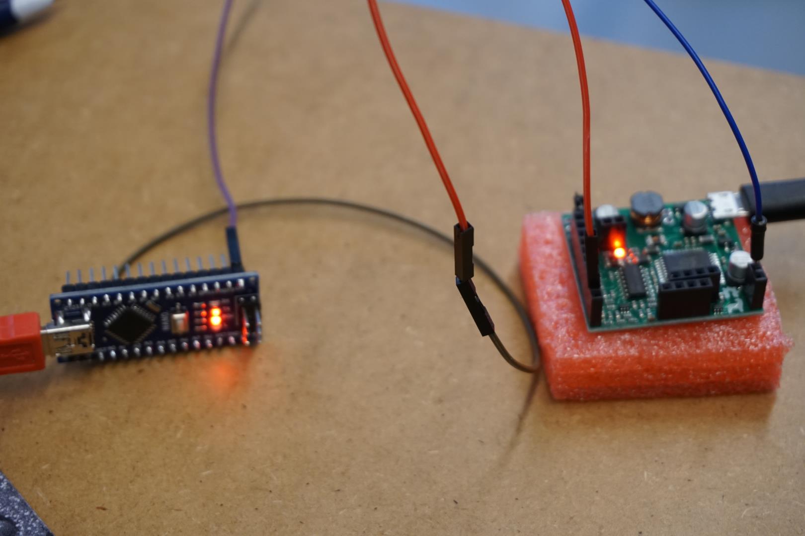
Again, using the pinout schematic from the site, I connected the two boards like this:
- Arduino pin
A0to the EspotekSignal Generator CH1 1 - Arduino pin
TXto the EspotekLogic Analyzer CH1 1
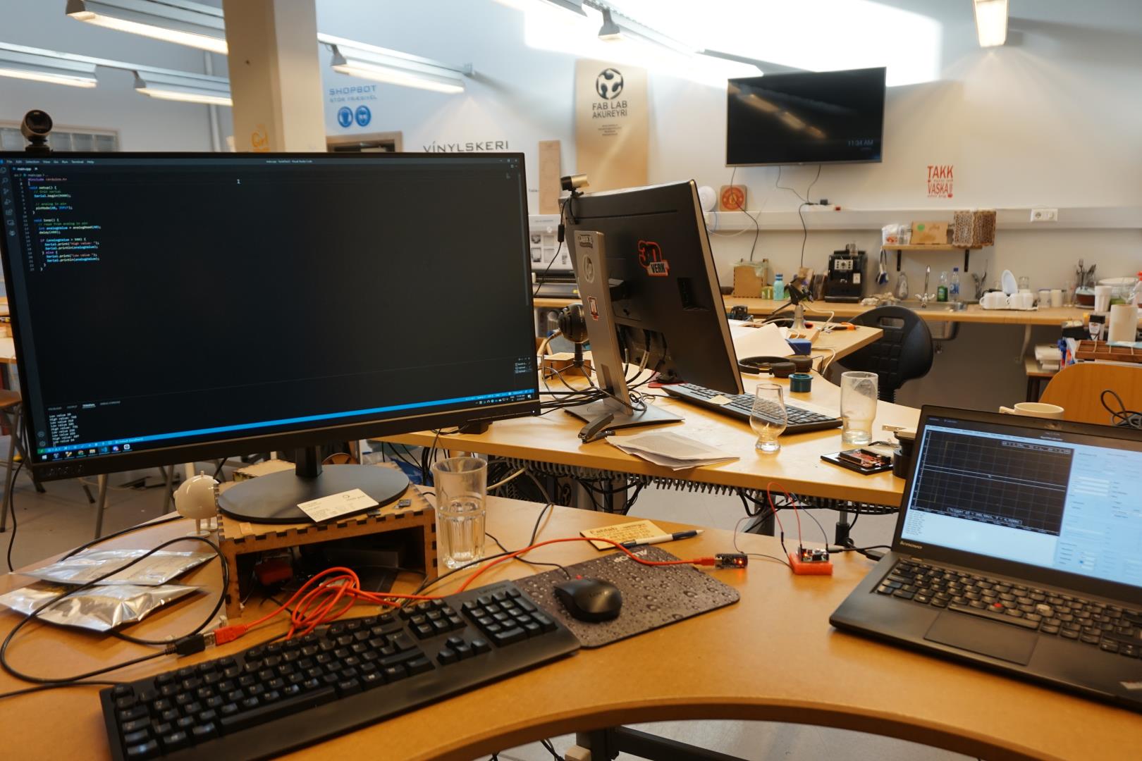
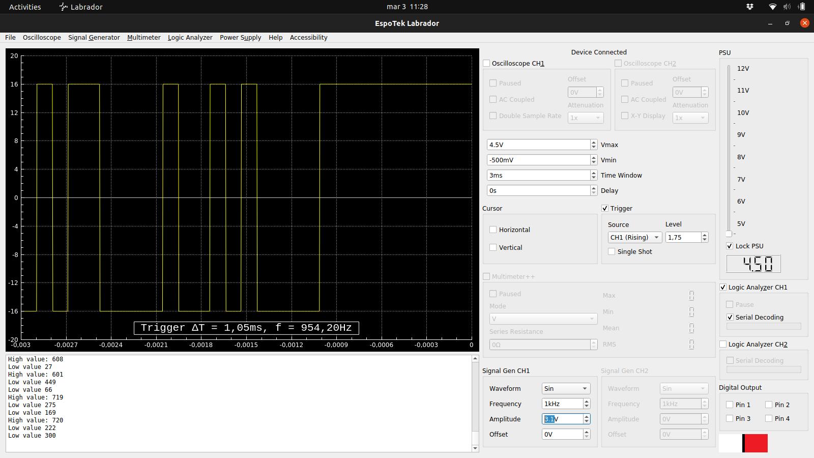
With the program loaded to the Arduino Nano, I can see the output in my Windows PC desktop terminal window.
On my Ubuntu laptop, I load up the Espotek software set it to generate a sine wave. The Arduino report if it’s a high or a low value!
In the EspoTek software I enable Logic Analyzer CH1 and below that, enable Serial Decoding. Then I can see the same output in the Espotek software output terminal. Neat!
After a bit of tweaking, I managed to view these nice pulses in the EspoTek software!
I’m sure to try this again with the board I make. Since it will be simpler than an Arduino, I’m looking forward to see if I can inspect the actual circuit in more detail.
Fun stuff and from a non electronics engineering perspective, I’m rather thrilled with this tiny piece of hardware.
Electronics design
Next mission: Creating a circuit, based on the hello-echo board.
After digging through our inventory, and a recommendation from my instructor, I decided to base it on the attiny 412.
I loaded up KiCad, created a new project and started messing around with it. I had previously loaded the Fab electronics component library for KiCad into KiCad and decided to check for an update:
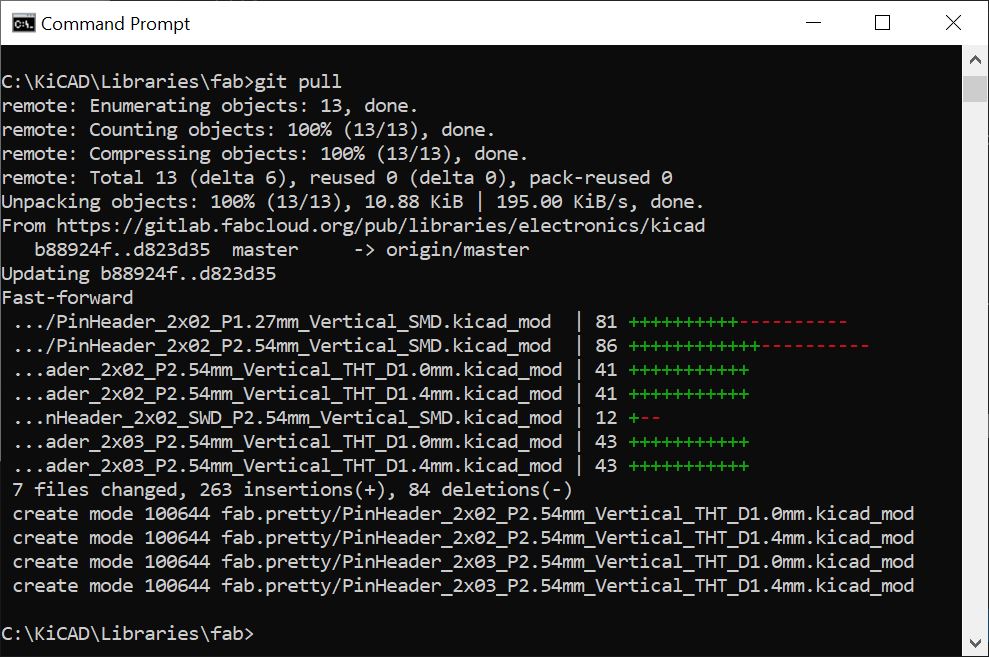
Wonderful, this is so nice!
My board
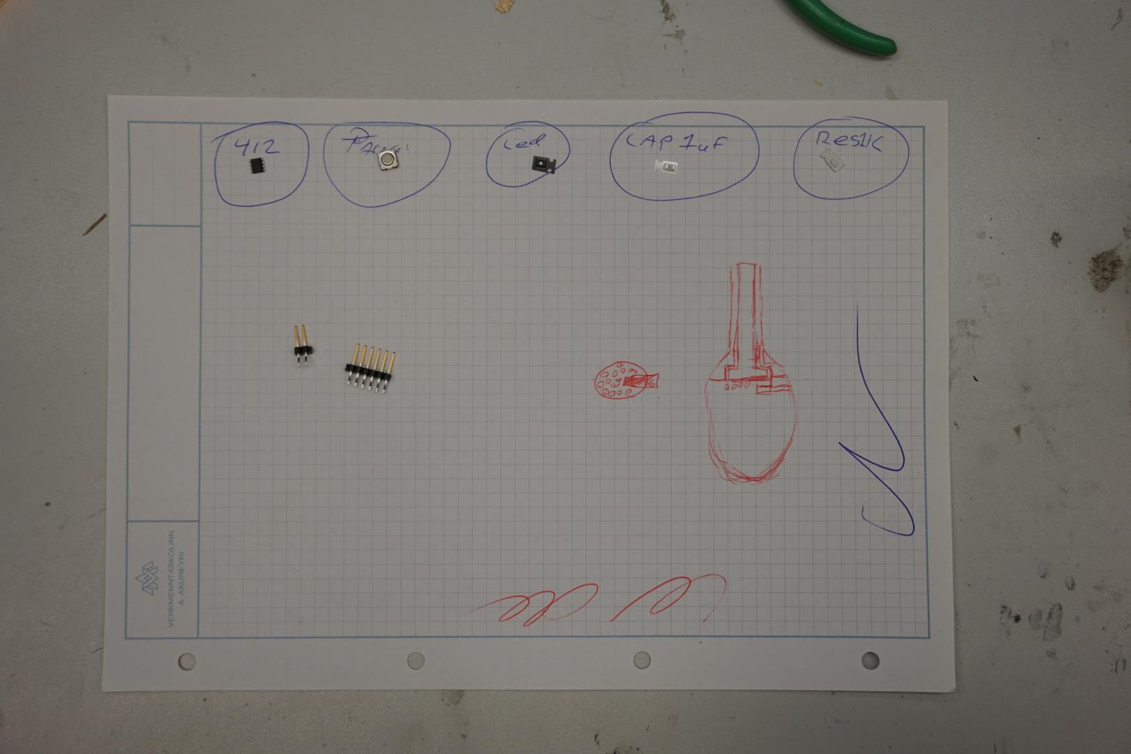
The idea is to base it on the echo hello for ATtiny 412 but to add a button and a LED. Looking at the schematics, both for the hello echo and others on the academy site, I decided to add the following to the schematic:
Button: `PA7` -> Button (R1) -> Button R(L1) -> `GND`
LED: `PA3` -> Resistor R1(1k) -> `A` (anode (+)) on LED -> `C` (cathode (+)) -> `GND`
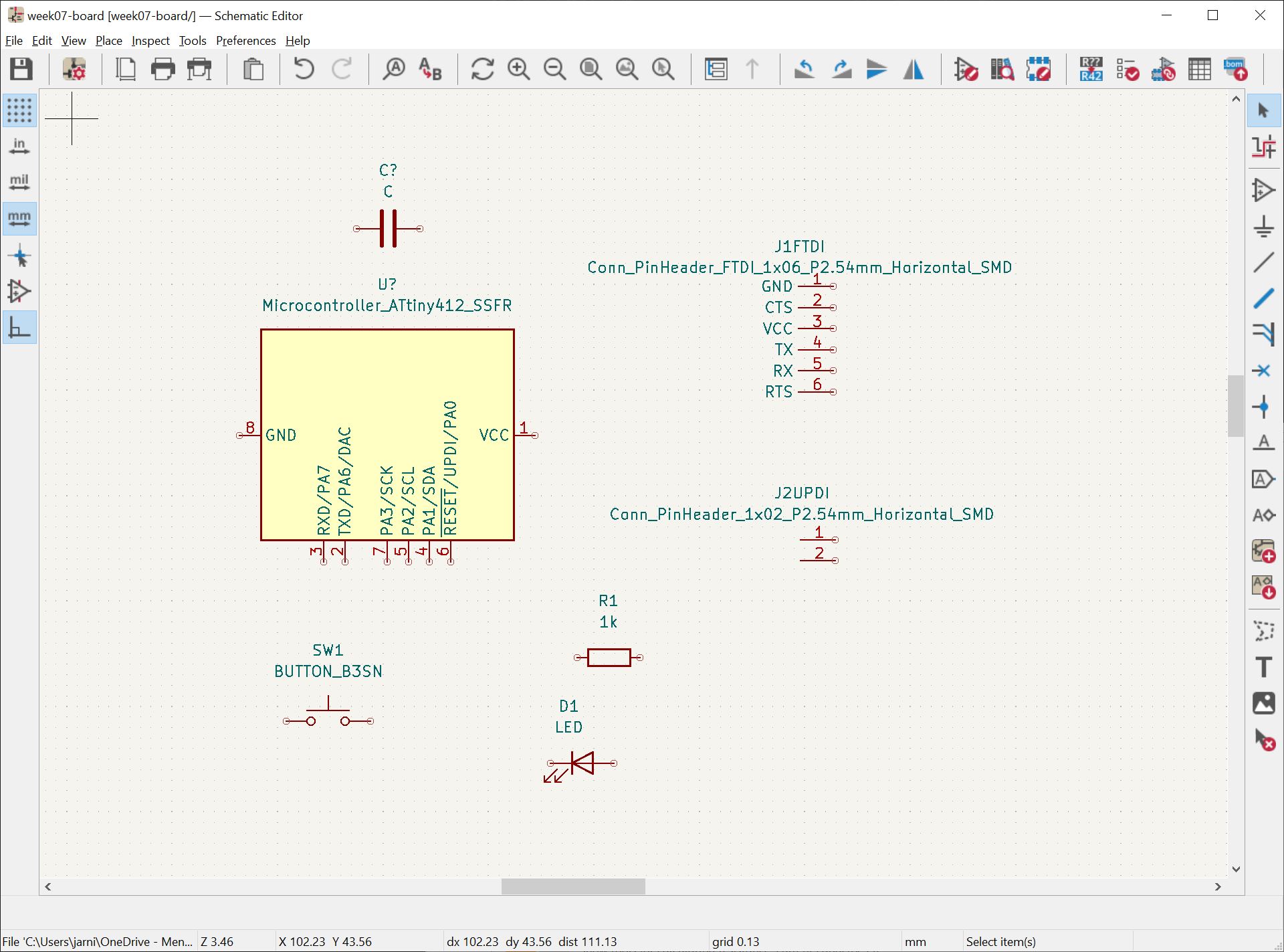
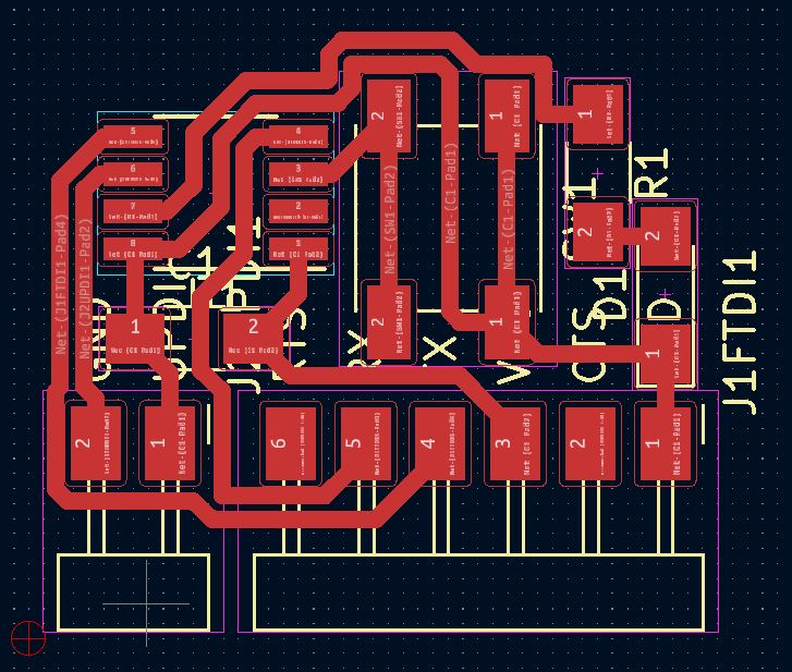
Here I have added the components to the schematic, next I need to connect them.
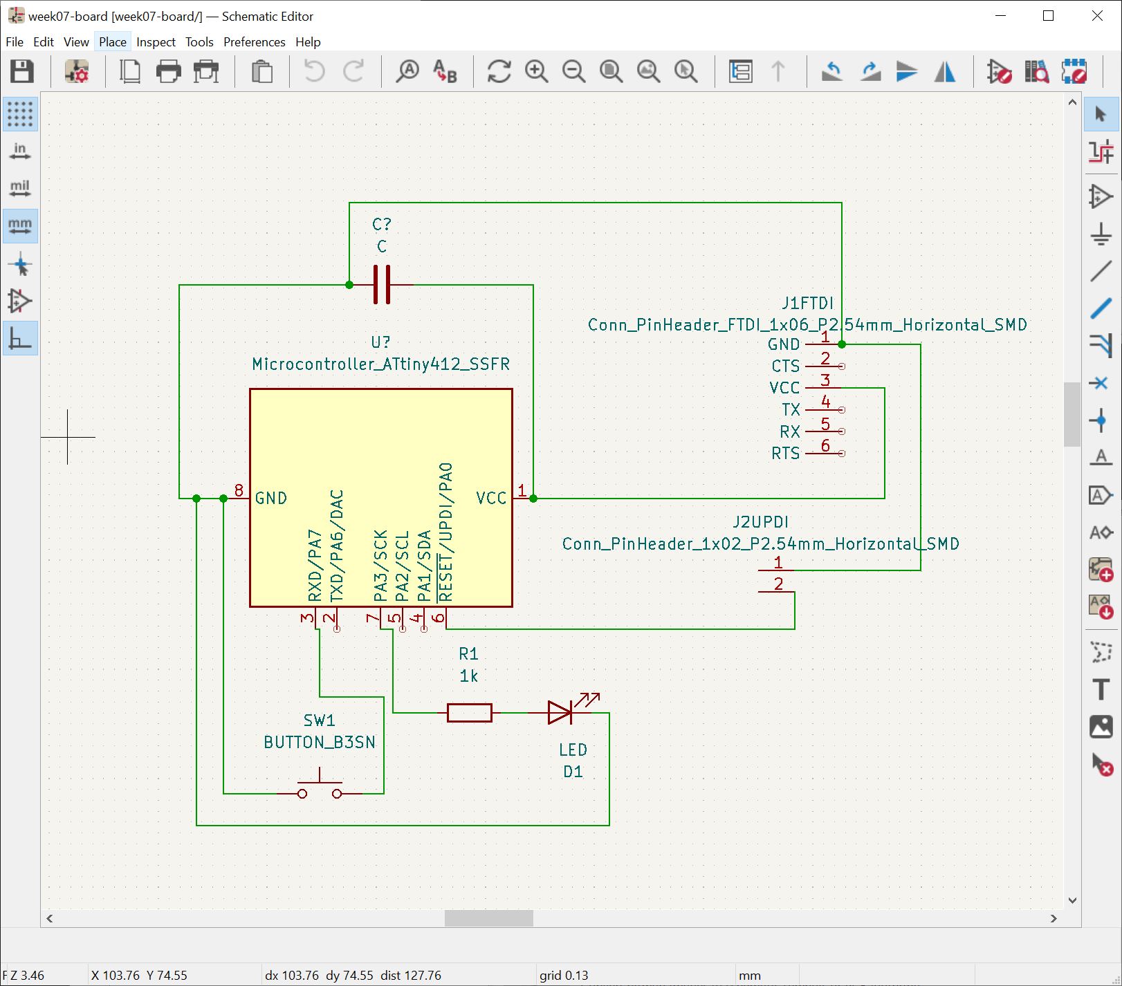
I then entered the PBC editor and hit the ‘Update PCB from schematic’ button. There were no errors and components were presented like this:
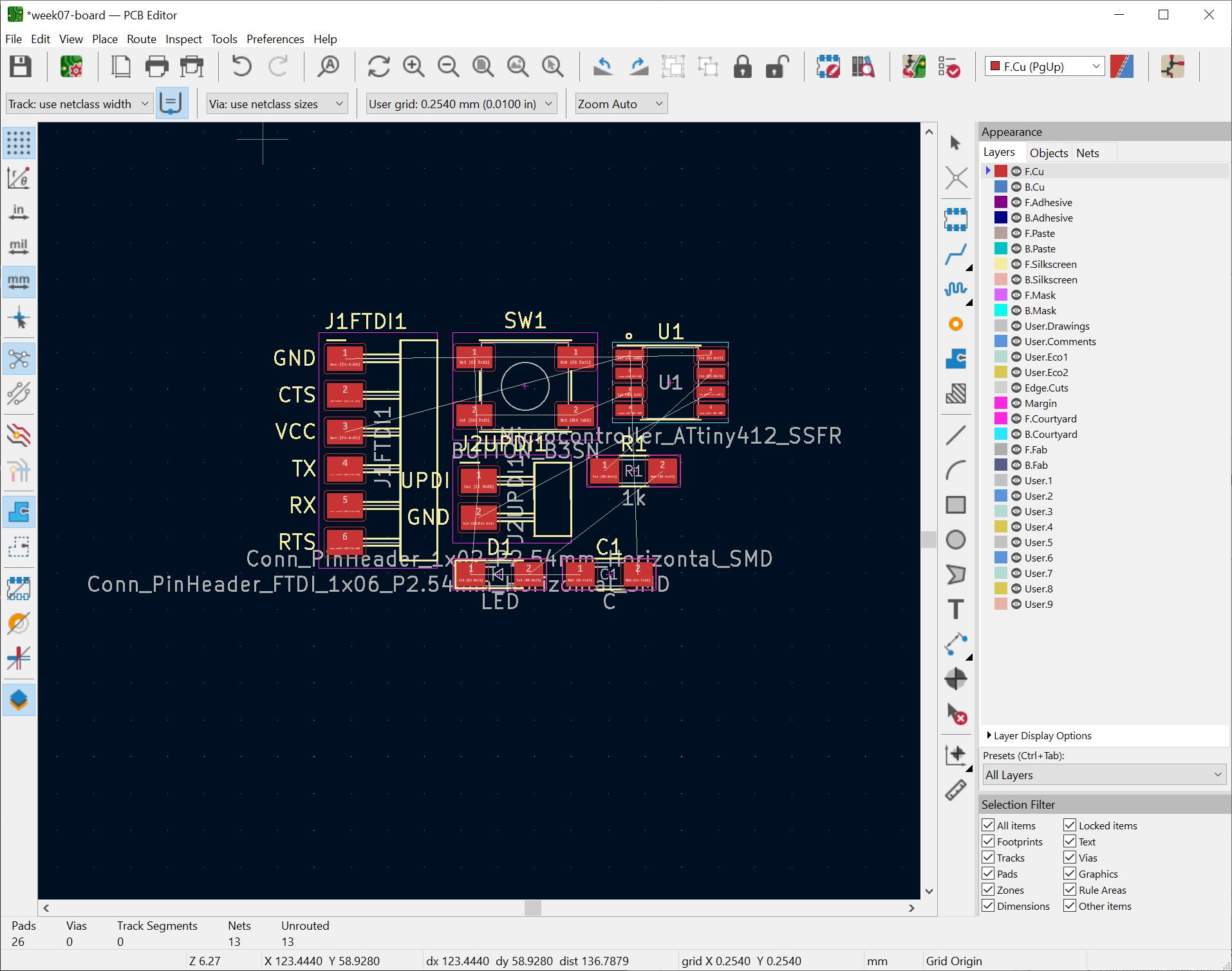
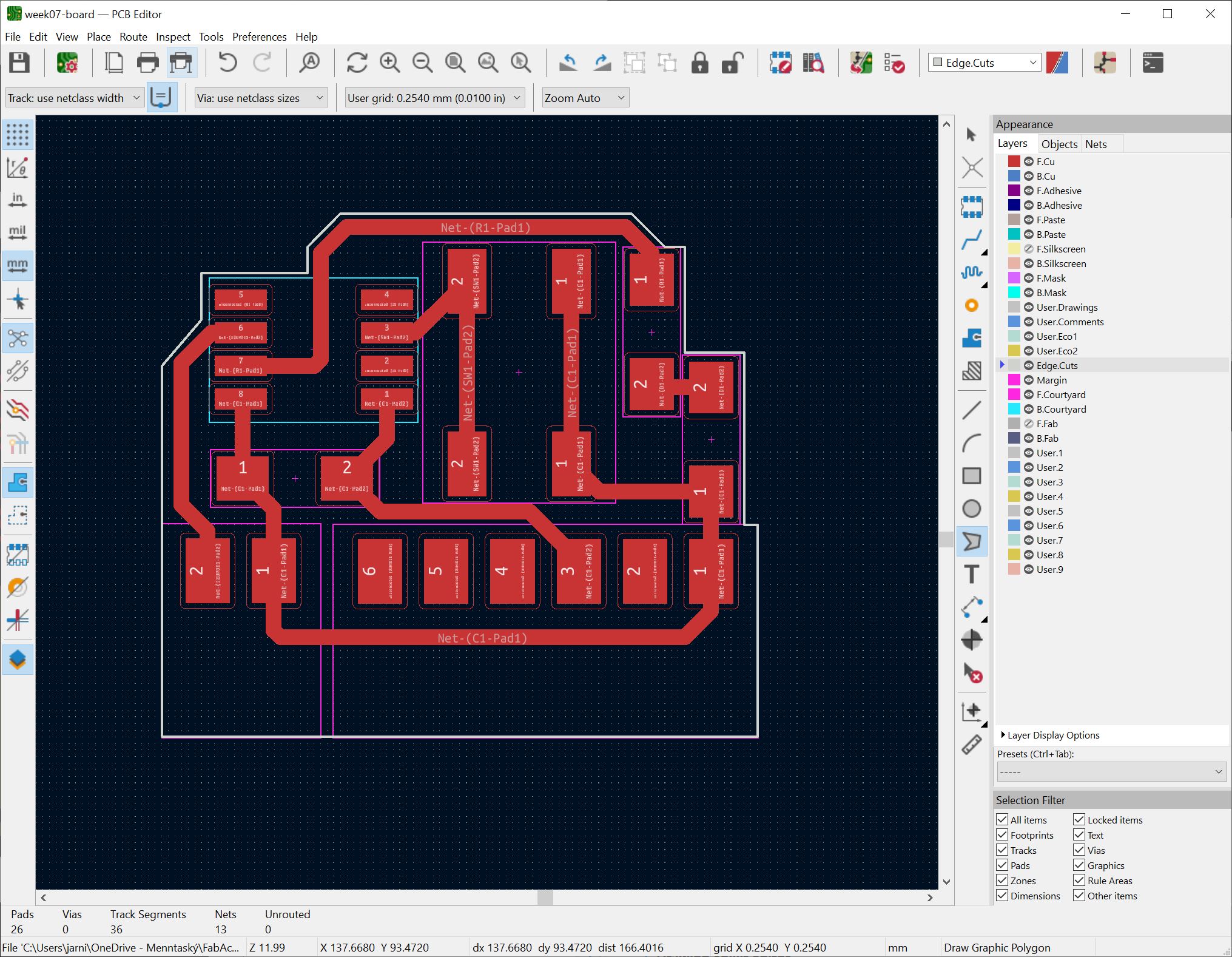
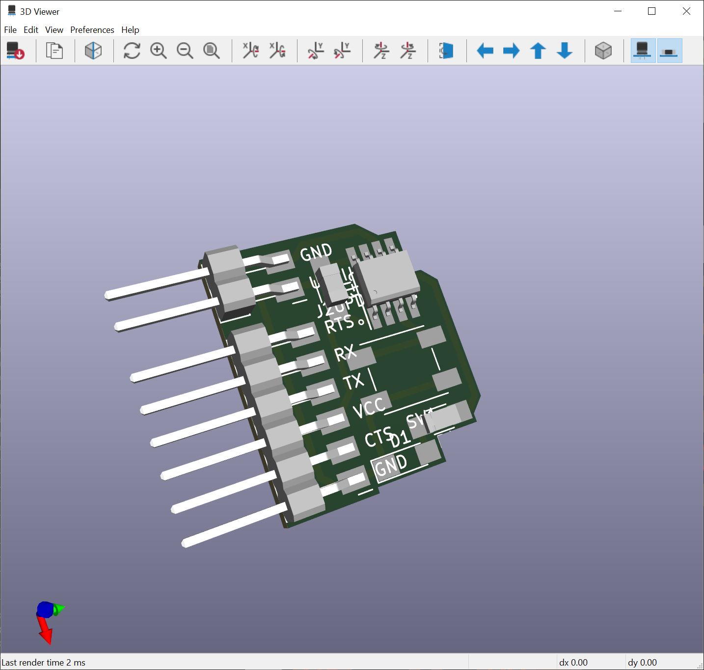
This quickly became a exercise in trying to get set up the smallest board. This is what I wound up with:
Milling and soldering
Warning: Troubles ahead!
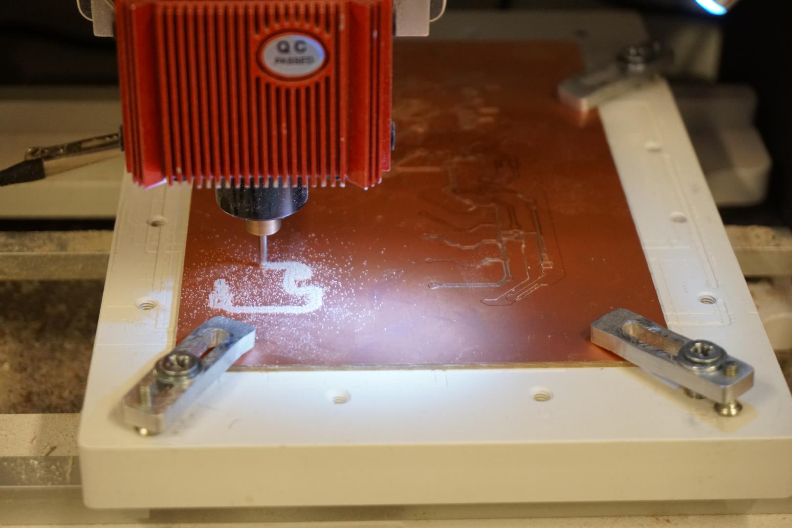
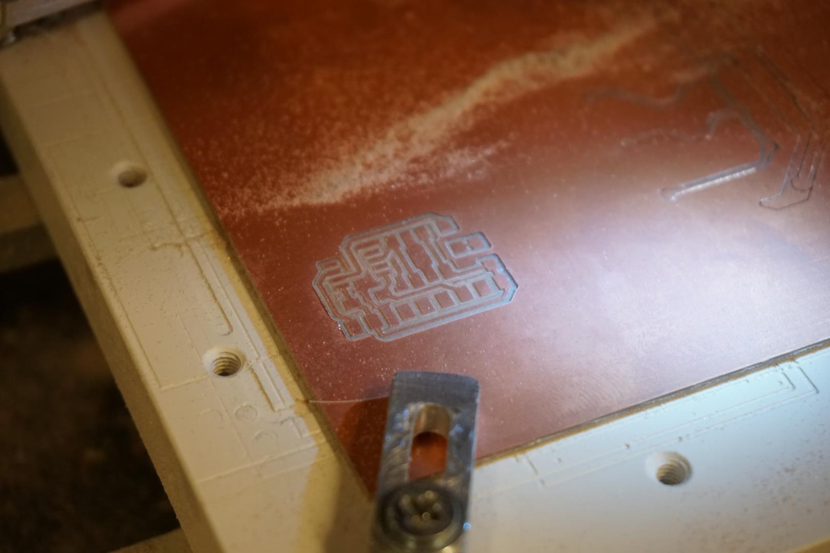
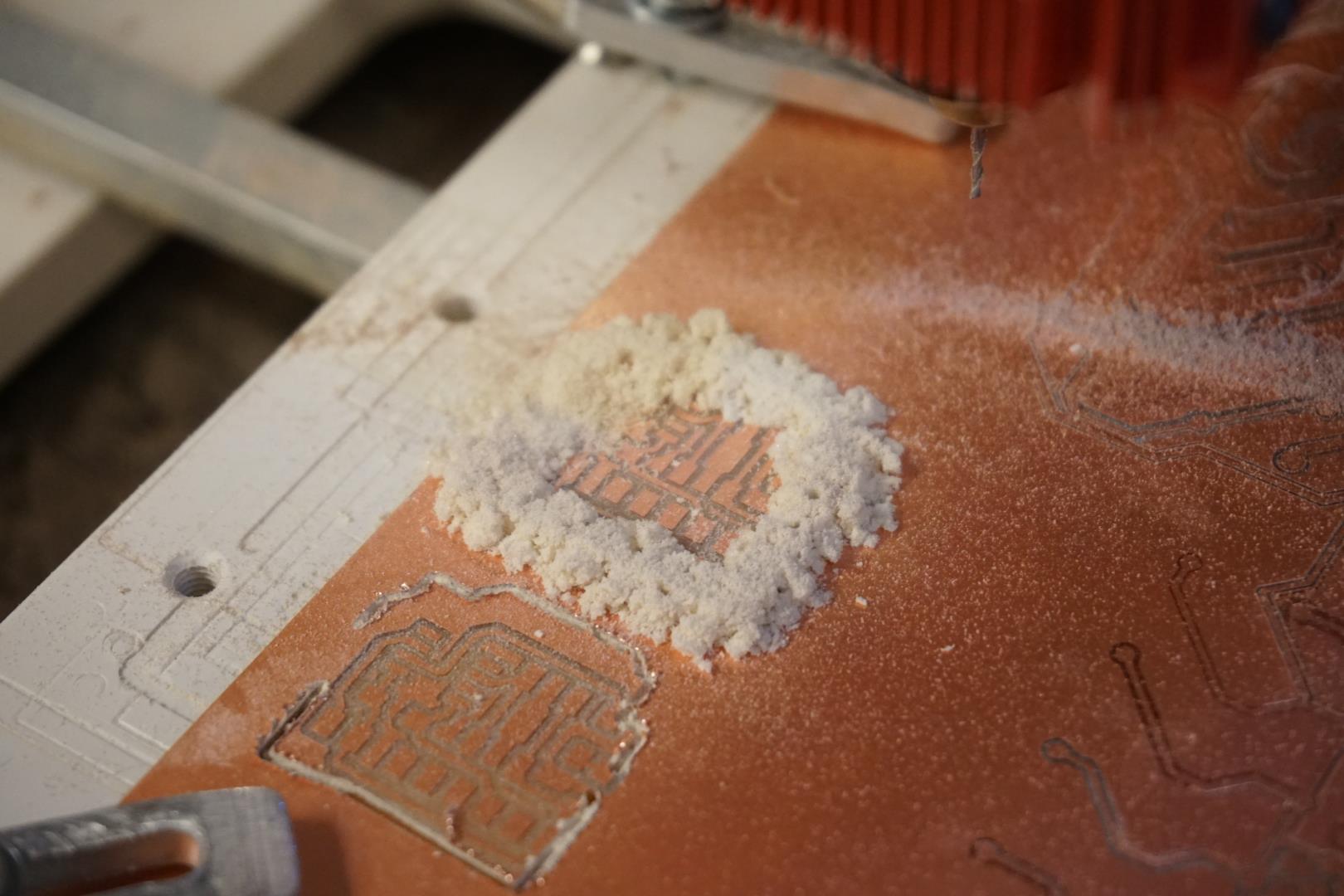
Using FlatCAM I created the CNC files and milled a board.
The edge cuts went well as pictured below:
First set of failures
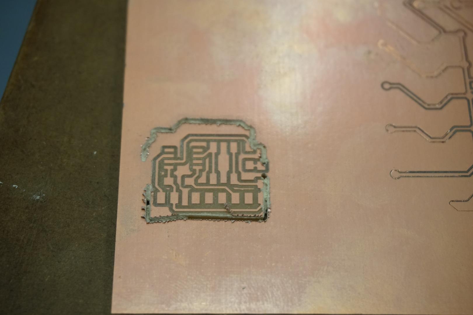
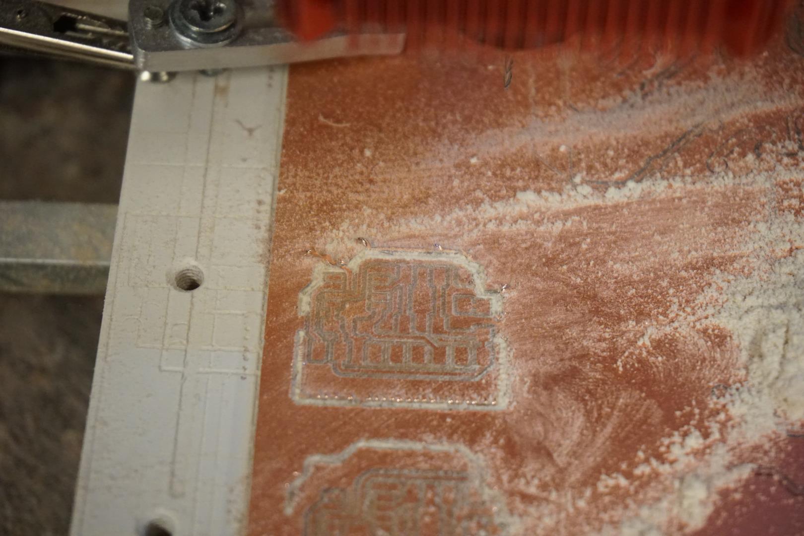
I did not notice that the drill I grabbed from the workbench was broken and thus the performance was not good. I actually pushed the PCB around in the mount, causing it to go of course. I would have used it if it were only cosmetic damage, but it damaged pads so I had to scrap it and start again.
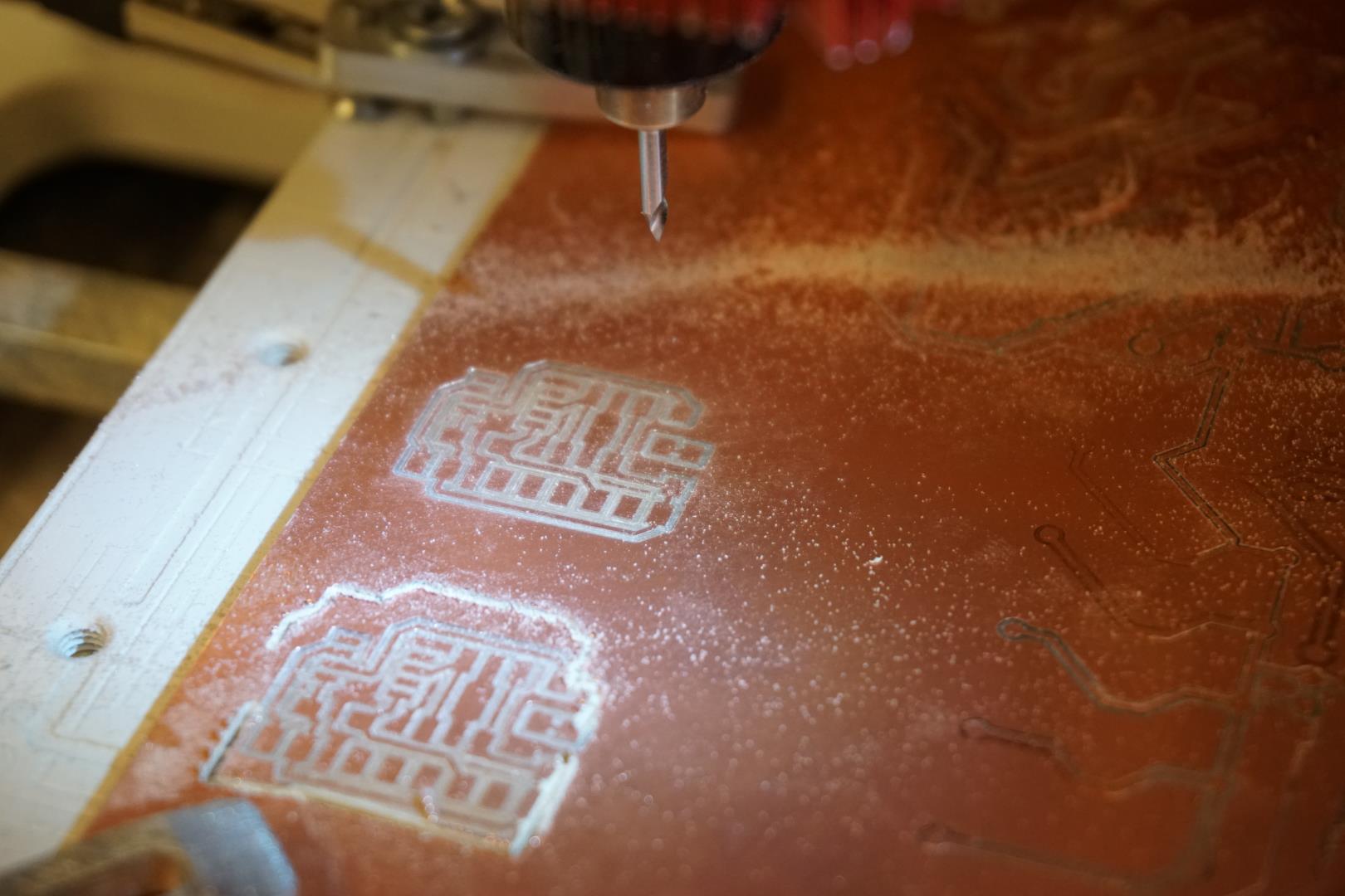
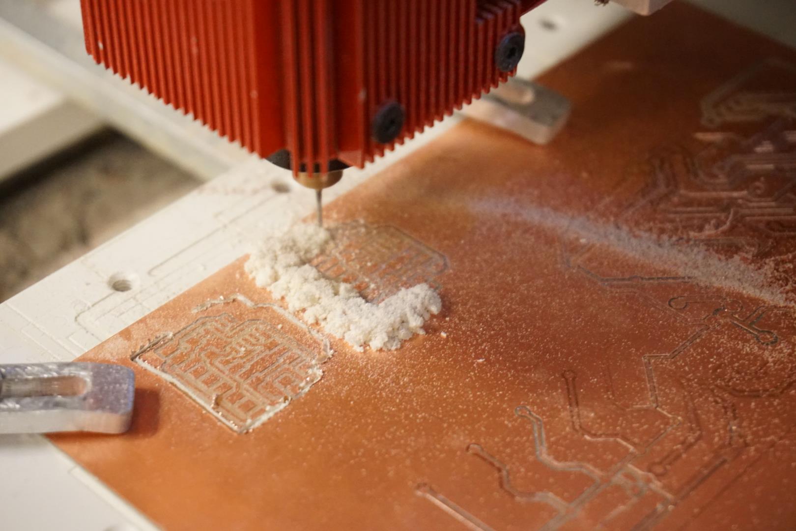
I then found a better drill which performed as expected.
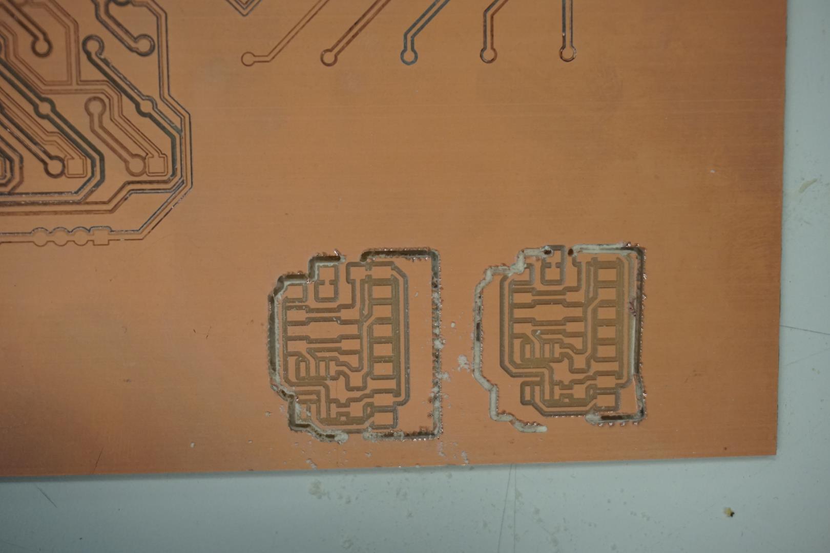
Then I cleaned it, filed the edges and matted the surface.
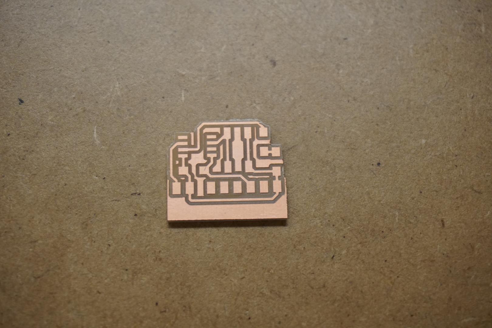
Well now, on to the next batch of failures!
Now it’s time to start soldering. I really enjoy this process and at this point I was ready to take over the world. That was soon to change.
As before, I set the PCB on a little leather pad we have and started by soldering the smallest items, then moving to the larger ones. I used flux ‘water’ and a standard soldering station. This went very well and I was ready for the next stage.
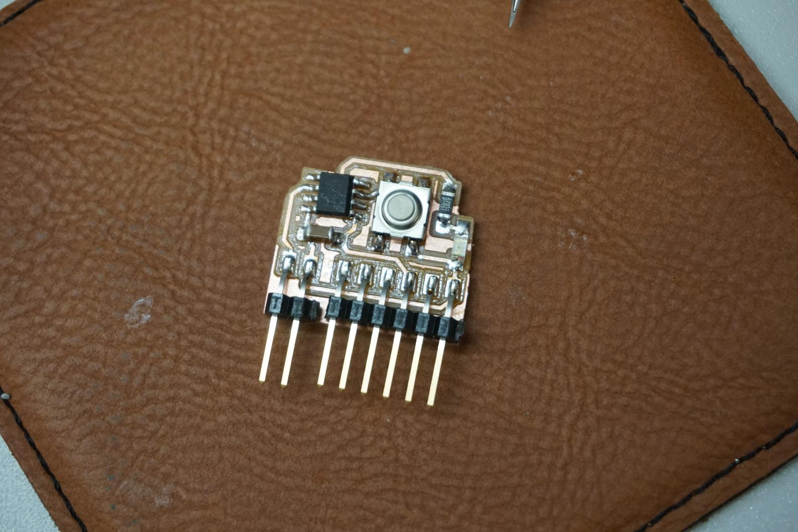
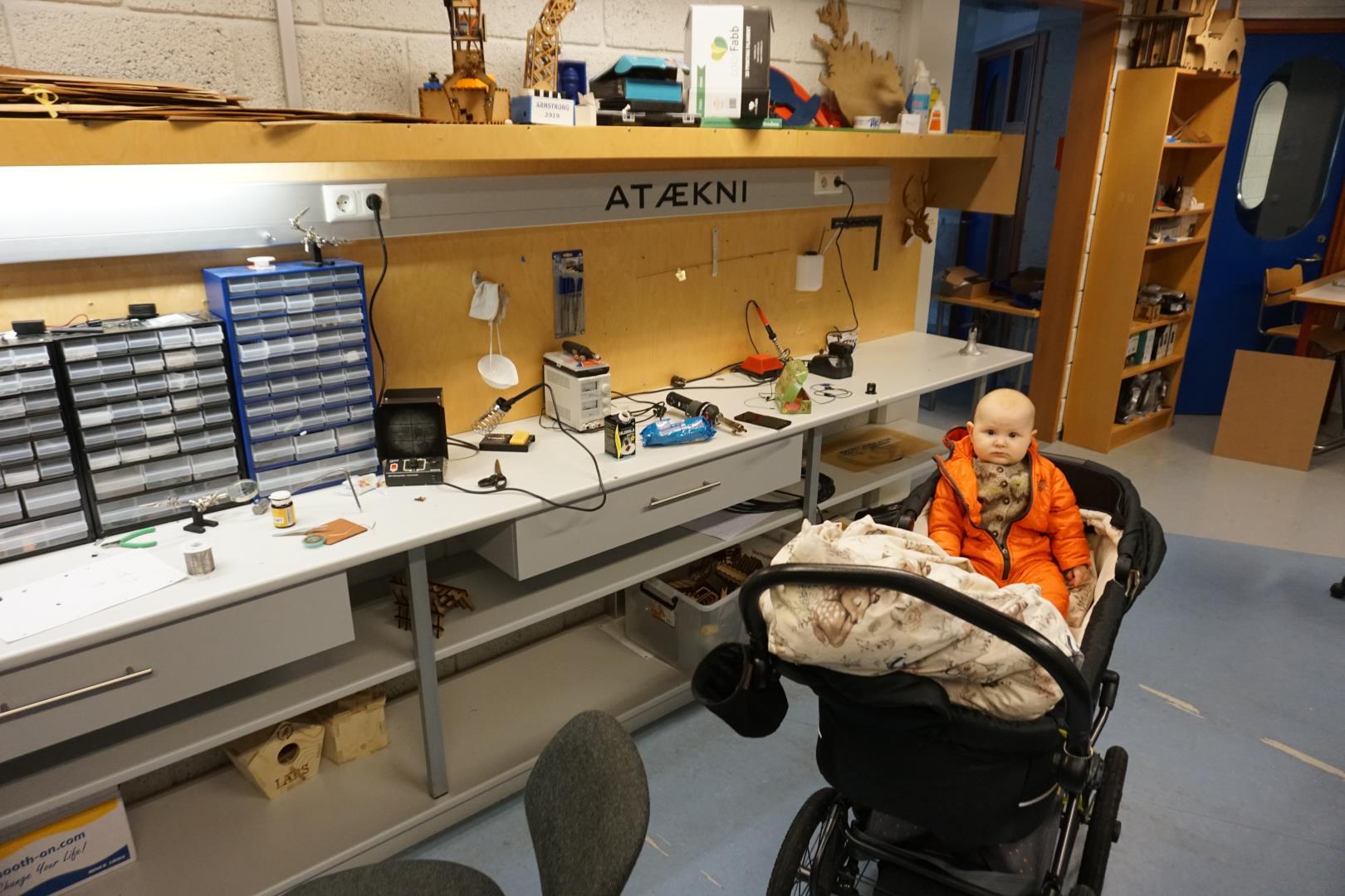
I had my mini-assistant with me, which was a gread deal of help.
Where are the failures you might ask?
Well, here they come! Turns out I had mixed up the GND and UPDI pins on my board, so when I connected it I found the chip quickly became hot and then I met Sparky, the magic blue smoke monster:
Well, hot damn! I quickly realized what I had done and then proceeded to try to unsolder the chip to replace it.
More failures!
That did not go as planned! I tried a hot air gun, which I had no great luck with. I then proceeded to try to desolder with braid… yeah, that did not work out! I pulled the copper from the board and that was it. I salvaged connectors and milled a new board.
Even more failures!
Making a new one was fast but once I started to program it I found it not working. One thing my dear colleague noticed was, that I had forgetten to make traces for the RX and TX pins! So with a couple of jumper wires, I was able to fix it.
Programming fail
Well, that was that.
Now, this is this!
And this is a bunch of more troubles!
Can Global Open Time help?
Right now, I’m throwing this together to participate in the Global Open Time.
The status now:
- I have installed megaTinyCore
- I have installed pyupdi
- Please notice that the README states the following:
This repository is no longer maintained. Use the serialupdi feature of pymcuprog.- Install pyupdi.py with pip directly from GitHub:
pip install https://github.com/mraardvark/pyupdi/archive/master.zip
- I have installed pymcuprog
- I have watched the Aalto Fablab video on UPDI programming
- I have set Arduino IDE to compile to an build dir, where I can fetch the .hex file.
- I have tried two UPDI programmers. Both register to the computer, same result.
And probably a bunch of other stuff.
This I have done on three computers.
- Windows 10 on both a laptop and desktop
- A Ubuntu 21.10 laptop
On Windows the programmer registers as COM[x] and on Ubuntu it is /dev/ttyACM0.
I have a TTL-232R3v3 cable, which I have connected to the board along side the UPDI cables.
I have also connected the UPDI, 5v and GND pins directly from the programmer to my board.
I have also grabbed a fresh ATtiny412, soldered 5v, gnd, and updi jumpers directly to it and connected it to the programmer.
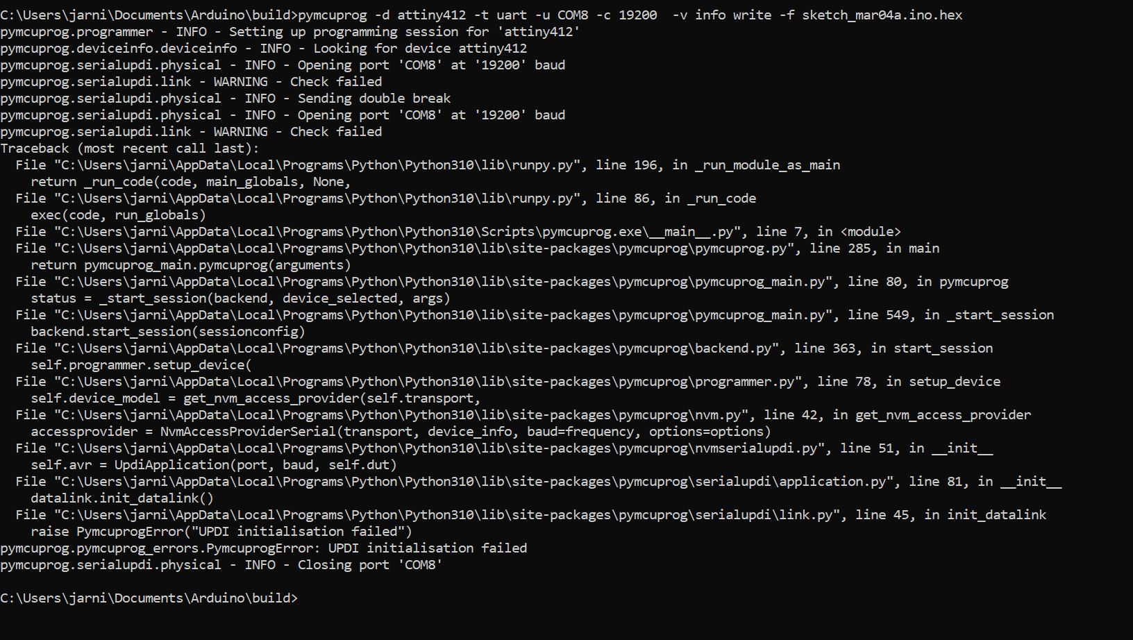
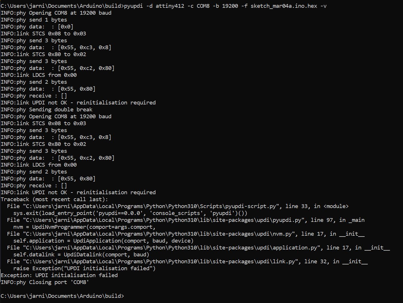
No matter what, I always get the same result:
Using pymcuprog:
Using pyupdi:
Update: Global Open Time to the rescue!
Well alright now, enough with the constant failures and troubles, let’s get to the good stuff.
My instructor and I attended the Global Open Time and I shared my ordeal. After a bit of back and fourth, Mr. Adrian Torres totally stepped up and saved the day.
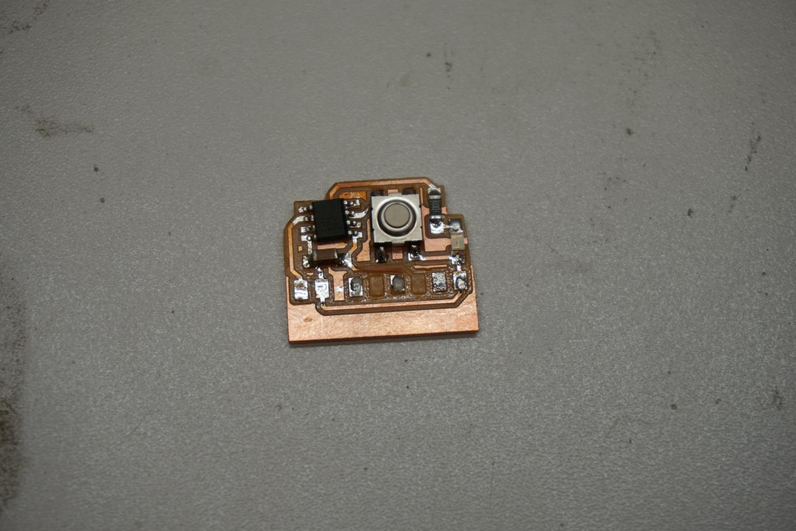
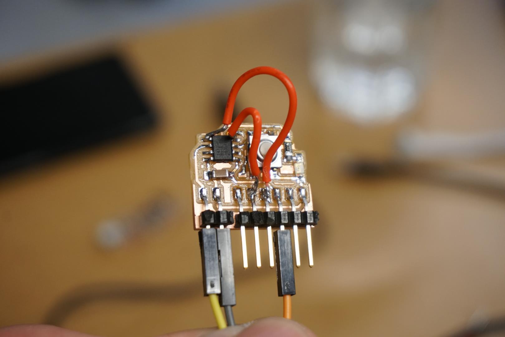
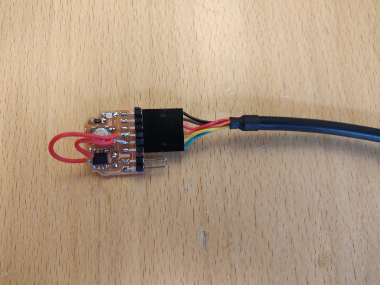
After we talked, we deduced that all signs pointed to the programmers. What we decided was the correct step in the debugging, was to try out the three pin FTDI to UPDI converter (serial UPDI-3 pin board components traces interior).
After creating this tiny converter board I was able to program the board!
Now I want to try to combine the steps needed!
Program a board with Arduino IDE
Prelude
I must admit, I had been a bit all over the place and was a bit confused what was needed and what not. So, to clear the path a bit, I grabbed a laptop with a fresh install of Windows 10 and decided to program a board with as few steps and troubles as possible and document the process.
So this aims at a Windows computer but the steps are very similar in Linux/Mac.
The steps
Stuff needed
-
Mill a board. For simplicities sake, pick a ready design from the Fab Academy site.
-
Grab a FTDI cable
-
Make the serial-to-UPDI converter board, I used the serial UPDI-3 pin version.
Software and setup
-
Install Arudino IDE
-
Add megaTinyCore to the Arduino IDE
- See the installation instructions here
-
Plug in the FTDI cable, give Windows a moment to install the driver. It should show up in the device manager, under Ports(COM & LPT) and show as COM[x].
-
In the Arduino IDE, load the sketch.ino file that matches the board you picked. (Write a new one once you maker sure your stuff works!)
-
Go to the Tools menu and select the following:
- Board -> megaTinyCore -> AT412/402/212/202 (or what matches yours)
- Chip -> Confirm the right chip is selected
- Port -> COM[x] (where x is the COM port number shown in device manager)
- Programmer -> SerialUPDI - SLOW: 57600 baud, any platform, any voltage, any adapter.
Connections to program the board
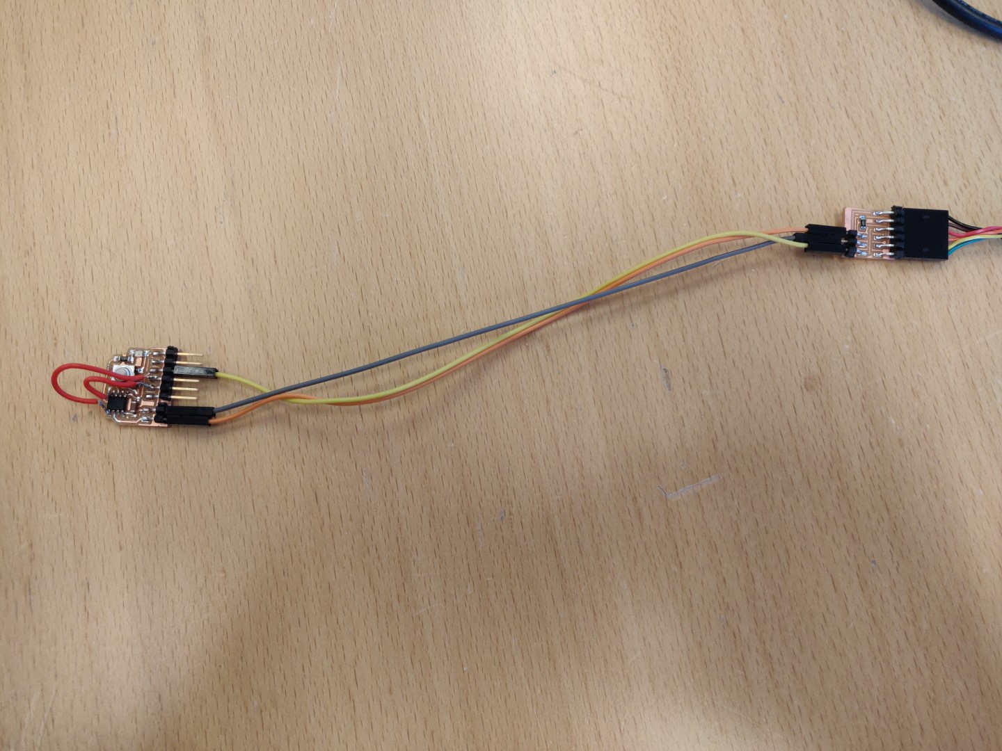
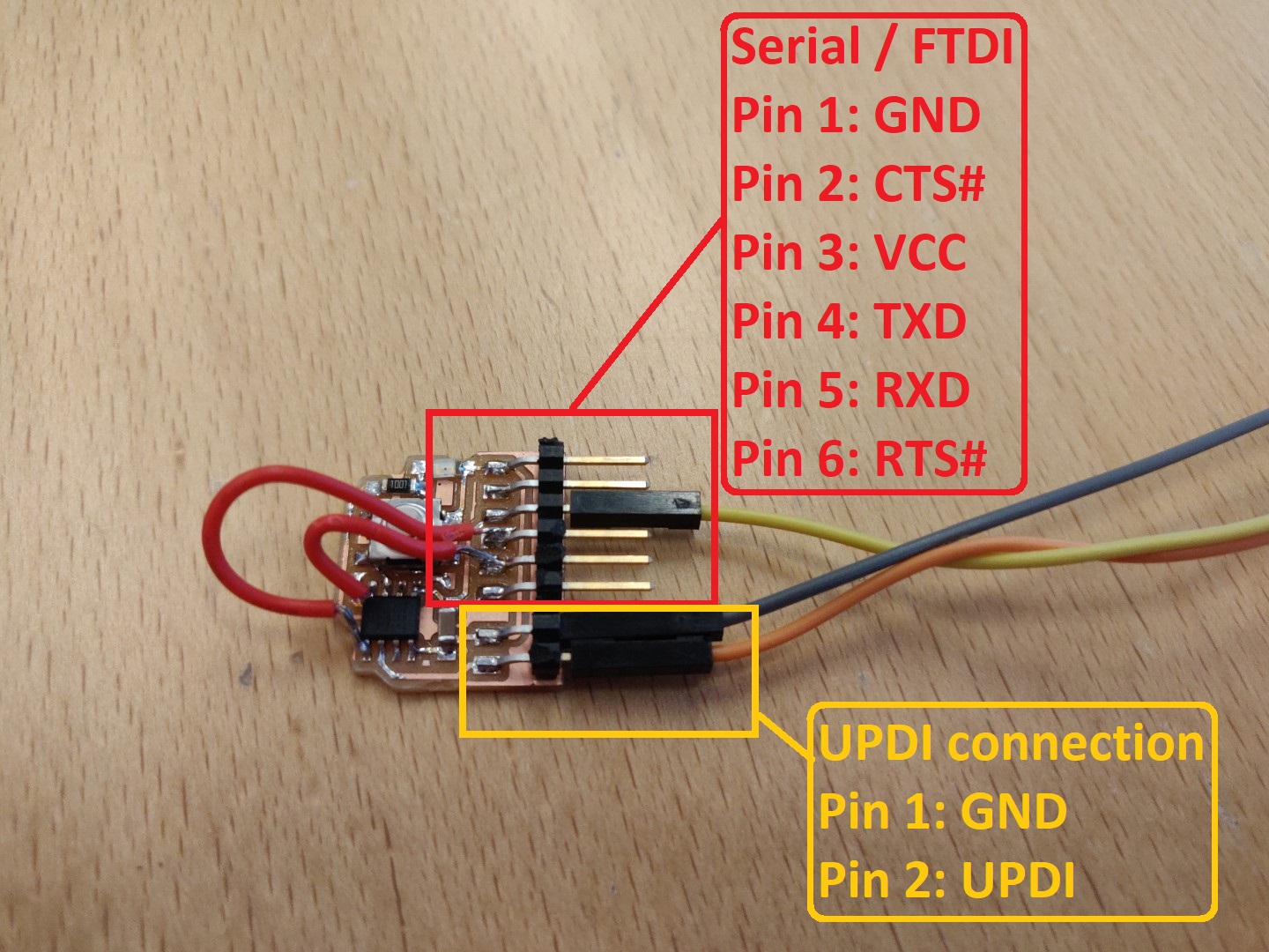
On the board I made, I have the 6 pin serial pins just above the two extra pins for UPDI.
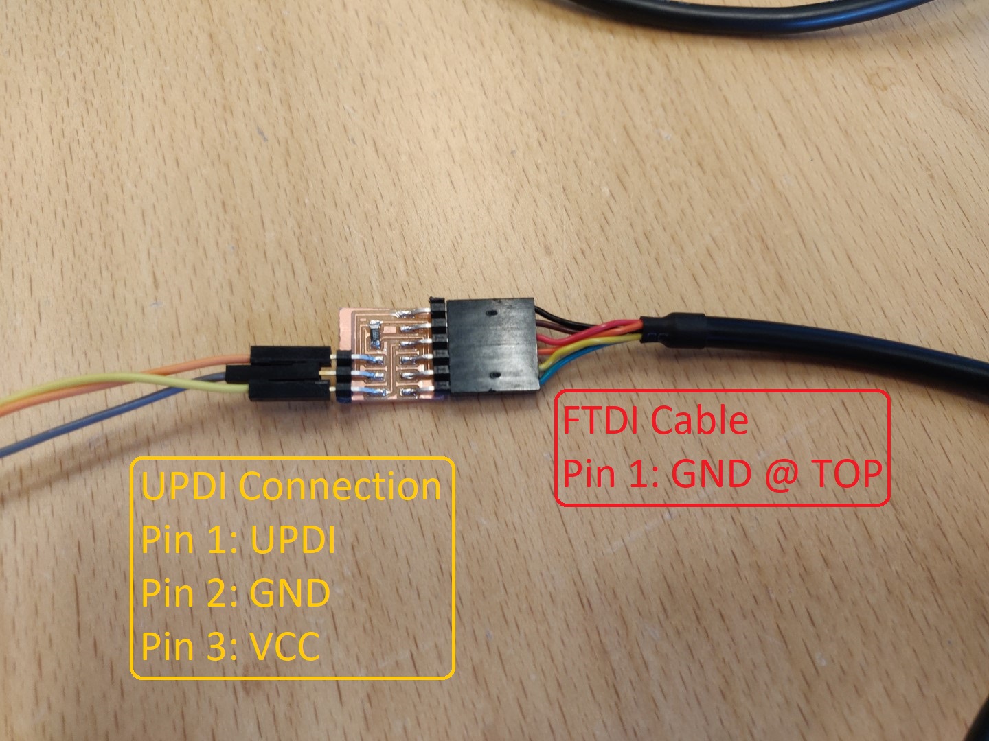
So to program it, you need VCC, GND and UPDI. Here they are connected on one end…
… and on the other end we have the FTDI cable connected to the converter board.
Please make sure you double check your own connections.
Programming the board
Now we are all set to program the board.
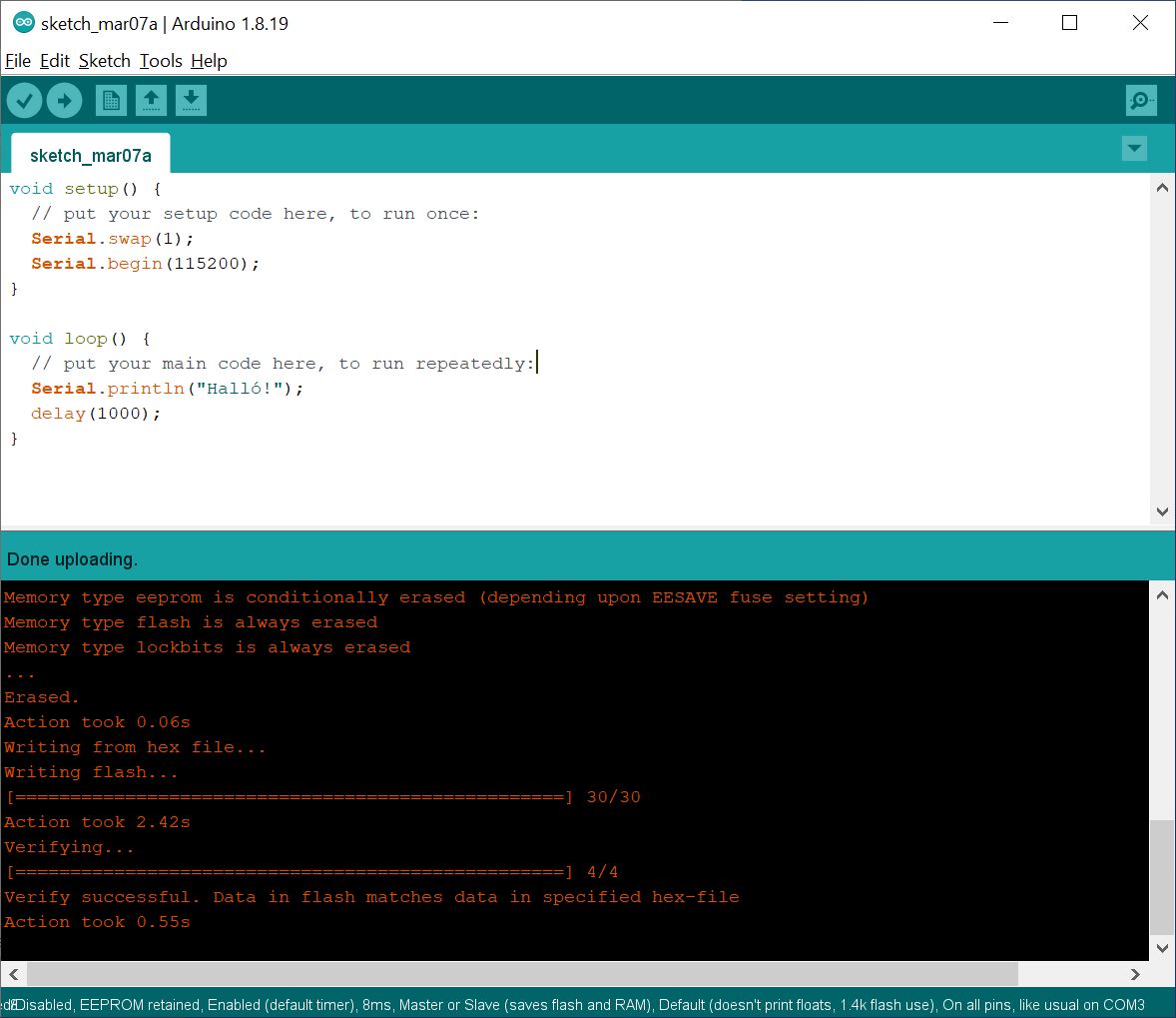
Make sure to use the appropriate .ino file and hit Upload.
For this demonstration, I use the following code:
void setup(){
  // This tells the chip to use pins PA1 and PA2 for serial instead of the default pins PA6 and PA7.
  // Double check your chip and design.
  Serial.swap(1);

  // Set the baud rate to 115200 baud.
  Serial.begin(115200);
}

void loop(){
  // Send a message to serial
  Serial.println("Halló!");

  // Wait for 1 second.
  delay(1000);
}
This will result in the following:
Now let’s test out if the serial communication works. Disconnect the converter board and plug the FTDI cable directly into your board. Make sure to orient the connection correctly.
Open serial monitor (Ctr+Shift+M) in Arduino IDE, select the appropriate baud rate (115200 in this case) and you will be able to see the messages.
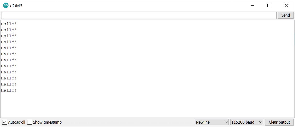
All right! I’ll call this a major success!
Program a with pymcuprog
Software and setup
pymcuprog is another tool for programming chips.
You must have python and pip before you can use it. Start by installing python. I got the python 3.10.2 installation file from the site and ran it.
I made sure to select Add Python 3.10 to PATH. This will the make sure the python executable available in the command line.
pip should be included in the install but you might need to restart the machine to get it to work.
Before you start, especially if python/pip was already installed, it might be a good idea to update pip first.
python -m pip install --upgrade pip
It should print out update information, if any.
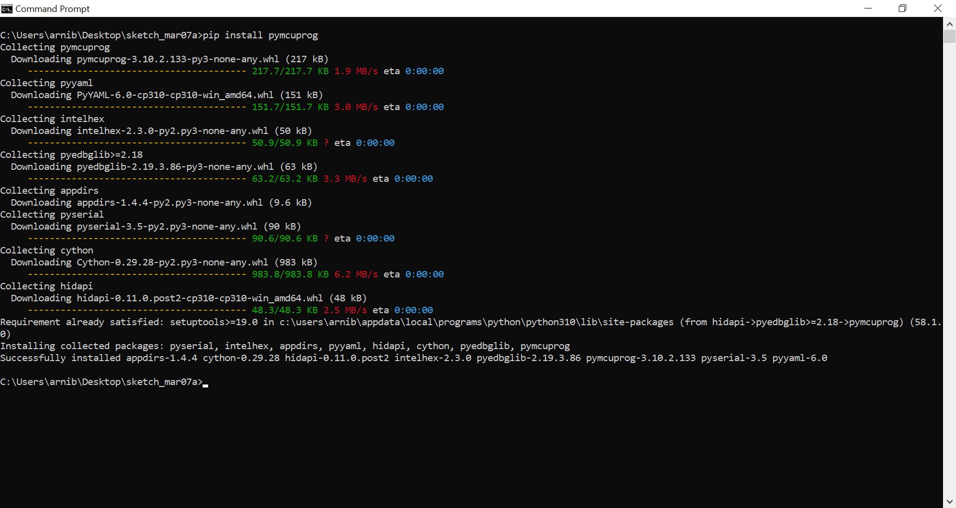
Then we can install the pymcuprog package.
pip install pymcuprog
Connecting the board
Now you must connect the board for UPDI programming. That means using the FTDI to UPDI converter board again, just like shown above.
Programming the board
pymcuprog accepts a .hex file as input. This is a complied file of your program. In our case, we use Arudino IDE to produce the HEX file.
In Arduino IDE, select Sketch and then Export compiled Binary(Ctrl+Alt+S).
This will produce the hex file in your sketch folder.
Within the terminal, CD into the sketch folder, in my case:
cd C:\Users\arnib\Desktop\sketch_mar07a\
and use the dir command to see the files in the folder.

One thing pymcuprog can do, is to ping devices to check the connection. Let’s try that first.
pymcuprog ping -d attiny412 -t uart -u com3
Please make sure to adjust the command appropriately to your setup.
This results in the following:
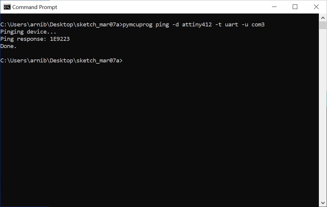
Brilliant! We have verified communications with the board so we can now run the programming command:
pymcuprog -d attiny412 -t uart -u com3 -v info write -f sketch_mar07a.ino.t412.20c0.md0.v259.hex
This will produce a long output, which ends in something like this:
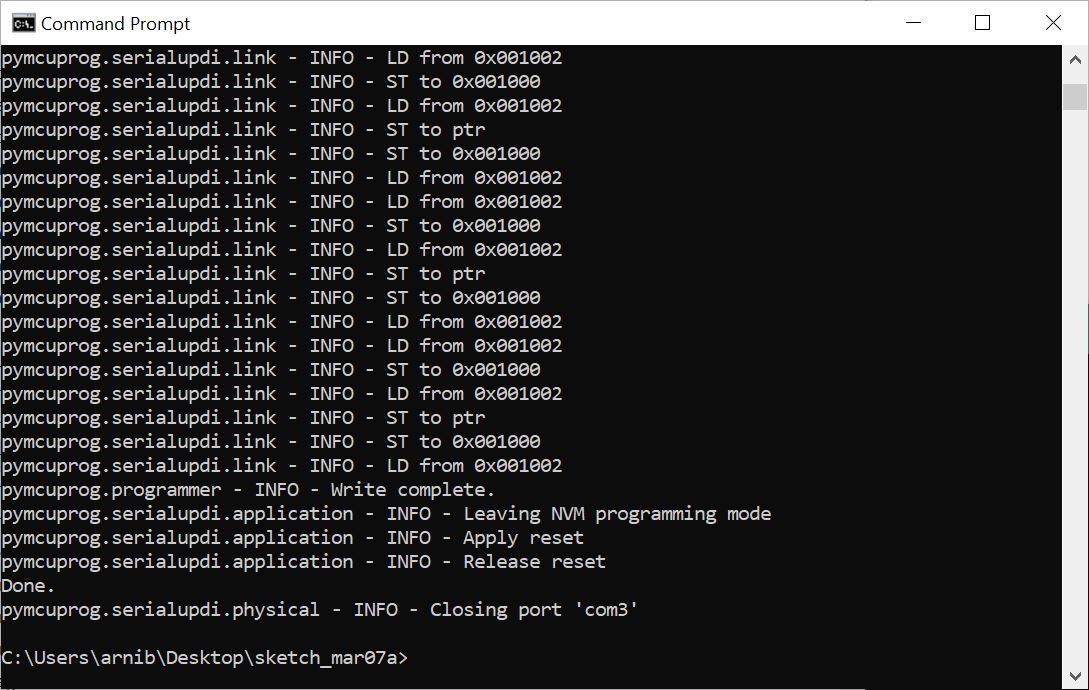
Important note
I found that if I wanted to update the program on the chip it did not suffice to just run the write command. I had to also run the erase command first.
pymcuprog -d attiny412 -t uart -u com3 -v info erase
and then the write command again.
pyupdi
pyupdi is another, older, library to program chips using UPDI. It is deprecated and I will not cover it’s uses here, though I can confirmed that it works.
Conclusion
I have yet to get the UPDI d11c programmer to work. This must be my fault but I’m afraid I cannot spend more time on it now. I already have two of them in my office plus the PCB’s that are in the mail! So fret not, I’ll be back to work on this later.
Maybe it’s a good thing that I spent a long time getting this to work, because I’m fairly confident now that I can program the chips the lab with just about any computer and operating system and future projects rely heavily on this.
Design files
| File name | Description |
|---|---|
| week07.rar | My KiCad project |
Updated board design, which includes the tx and rx pins.
TODO
-
Update KiCad design to include TX/RX pins.
-
Get the UPDI d11c programmer to work (on the way-back burner)