11. Output Devices
This weeks missions:
-
Add an output device to a microcontroller I make and program it to do something.
-
Measure the power consumption of an output device.
What to do
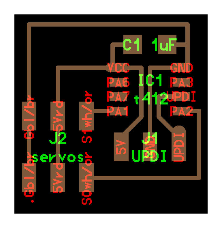
After a discussion with my instructor, I picked one of the servo boards from here, specifically the ATtiny412 one, called: “hello.servo.t412”.
Here is the schematic given:
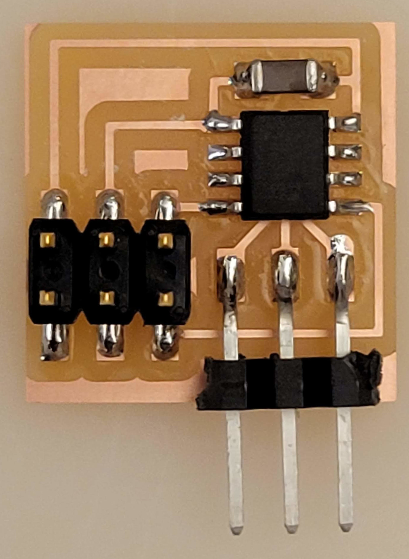
and how it looks built:
My board
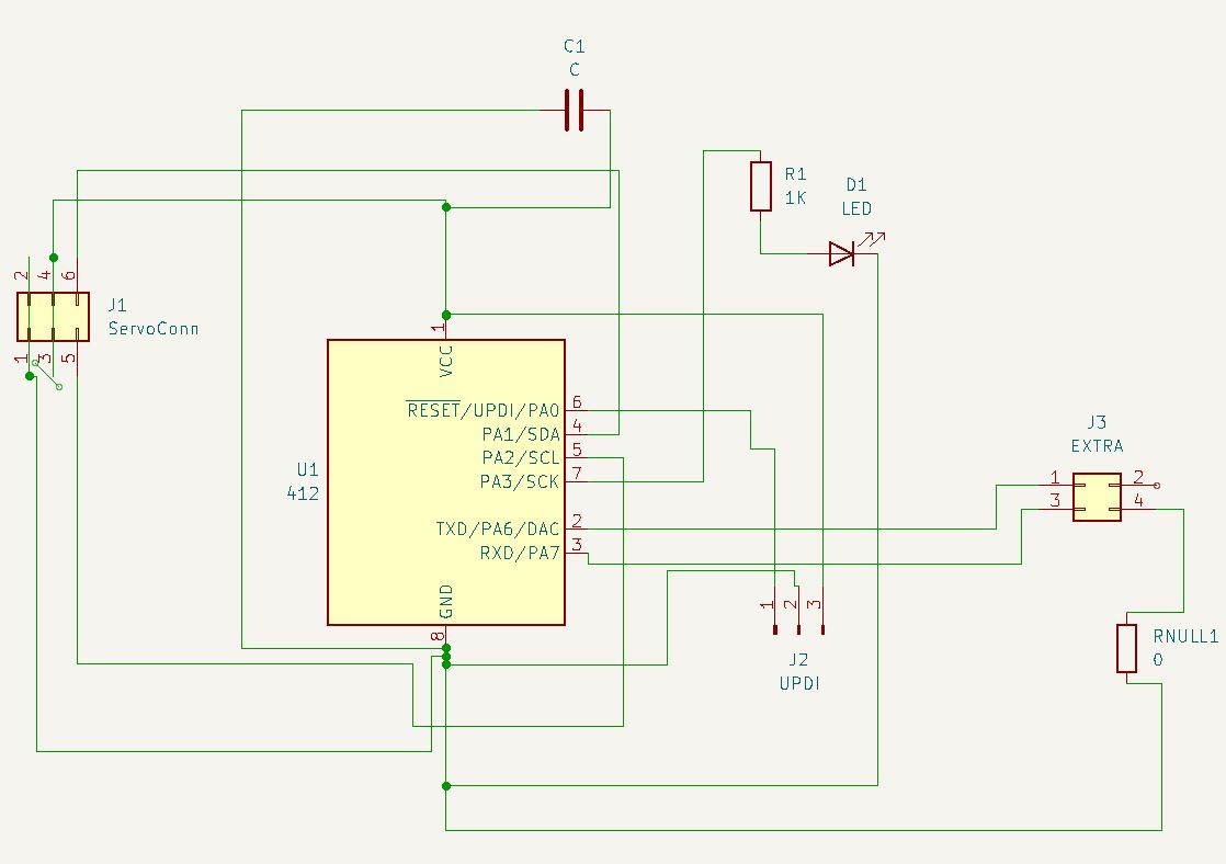
I figured I’d base my design on this one, adding a diode and pins to be able to get further use out of it, such as connected another output devices, another board or communication. The extra pins are PA6 and PA7, which are the default serial pins.
The schematic
Using KiCad and fab library I started by duplicating the schematic given above, and added the following:
| Component | Description |
|---|---|
| Diode | A diode to connect to the servo board |
| Resistor | 1K ohm resistor for the diode |
| Connector | 4 pin connector for the extra pins |
| Resistor | 0 ohm jumper resistor |
The original board had the following components:
| Component | Description |
|---|---|
| ATtiny 412 | Microcontroller |
| Capacitor | 1uF |
| Connector | 3 pin connector for +/-/UPDI |
| Connector | 6 pin connector for the servo board |
I have not gained much experience with KiCad, but I like the software. Yet I know have much to learn, to get the most out of it.
For a beginner like me, having the layout clear and plenty of space helps.
The PCB layout
I save the schematic and open the PCB Editor in KiCad. The first time you open it, it’s completely empty, even though you schematic is ready.
You must run the Update PCB with changes made to schematic function, which is either by hitting F8, by selecting Tools and Update PCB with changes made to schematic or by selecting the icon in the tool bar:

When you hit it for the first time, you are presented with all the items clustered to gether. You must then arrange them to your liking. Also, if you go back into the schematic and change it, you must hit this to refresh the PCB layout.
For this board, I only use two layers:
F.Cu: the top layer, where the components are placedEdge.Cuts: Where the outline of the board is placed
This time spend some time arranging the components to my liking and I also add some text for the first time! That’s simple, you just hit the T icon on the right toolbar and input what you like.

You just have to remember which layer you are working on! I put the text on the F.Cu layer, since I just want it etched, not drilled out.
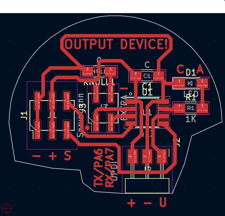
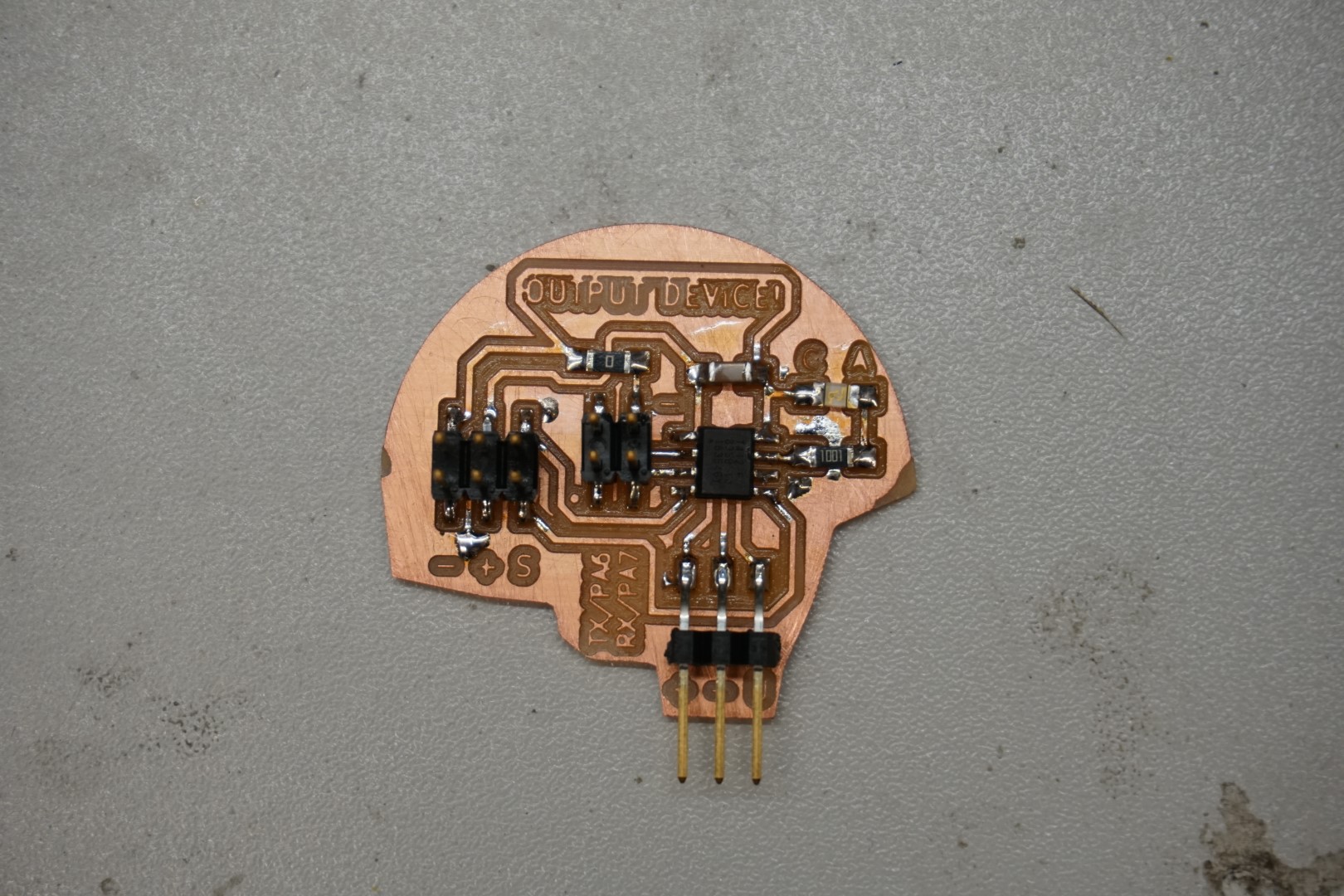
You can see how I used the null resistor as a jumper, allowing a path to “jump” another. It’s located just below the “OUTPUT DEVICE!” text.
I put in the name of the board and markings for the pins, along with the (A)node and (C)athode markings of the LED. This is just to help me and speed up working with the board. I find it tedious to have to constantly look up the layout when working on the boards. This is a very good thing for me!
There is no reason for the funky shape, other than to create a funky shape. I just wanted to test out combining a semi circle with polygons, which was no trouble at all.
Last thing to do export the gerber files, to preparing the milling.
To do this, you must select File, Fabrication outputs and Gerbers.
For this design, we’re only the two aforementioned layers, so we don’t need to select anything else, only F.Cu and Edge.Cuts.
On the picture above, you see the red crosshairs? That’s the origin point. So when exporting, remember to select Use drill/place file origin in the Plot dialog.
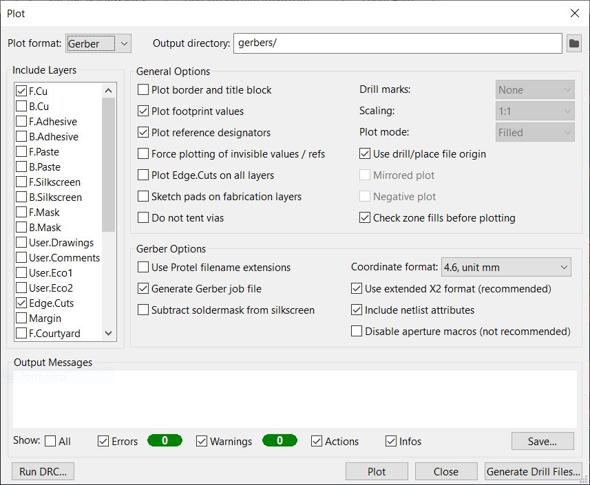
Just select your output folder and hit Plot!
In this case, we don’t need any drill files, as we have no through-hole-components.
Milling
For preparing the milling, I use FlatCAM to generate the NC files and mill the board with a Wegstr CNC machine.
FlatCAM
I’ve been trying out FlatCAM, the beta version (version 8.994) for a while now. Previously I’ve mentioned the Tool Database which is included in the beta. I find setting up the main tools once and then just selecting them when preparing the milling is a great feature, much better than having to remember all of the settings, especially when you’re working with multiple tools as a beginner. You can always make adjustments which will only help you make your milling better with experience and experimentation.
Tool Database
You open the Tool Database by going to Option -> Tool Database or Ctrl + D
I have set up two tools in the database (and one test tool). As mentioned before, this software is beta and it crashes when I try to remove a tool from the DB :)
As you can see, the DB gives you a dialog for each tool. It’s up to you what to do with it and you must take care of inspecting the properties of the tools and software.
The two tools I have set up are:
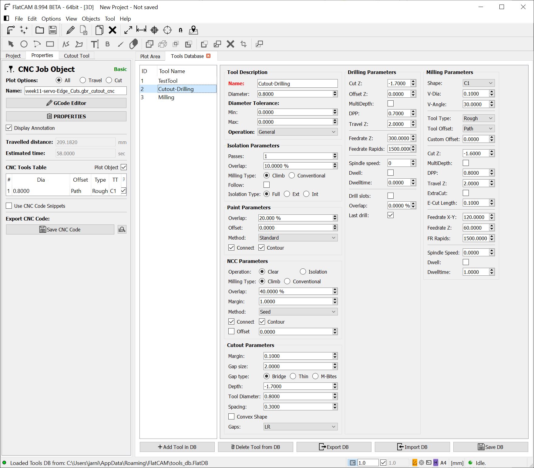
Cutout-Drilling tool
There I must setup the Cutout and Drilling parameters. The others do not matter, so long as I do not make the mistake of using the tool for other stuff, such as milling.
| My settings | |
|---|---|
| Parameter | Value |
| Diameter | 0.5 |
| Depth | -1.7 |
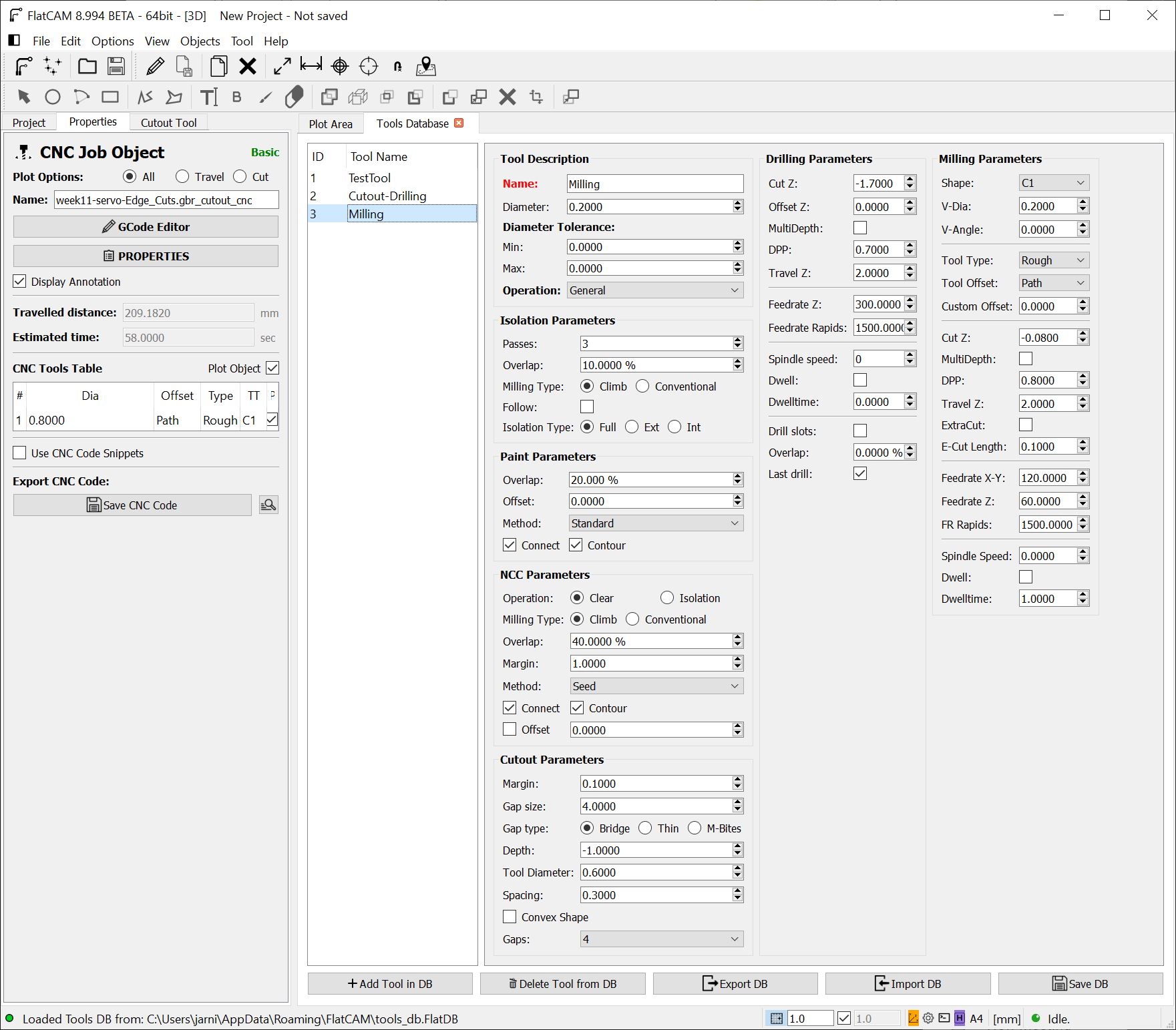
Milling tool
Here I focus on the Milling parameters.
The tool is actually a V-bit but with experience we use it as a flat end mill.
| My settings | |
|---|---|
| Parameter | Value |
| Diameter | 0.2 |
| V-Dia | 0.2 |
| Cut Z | -0.08 |
Note about the Wegstr CNC machine. There is no information displayed in the GUI about the spindle speed or feed rate. According to the website, the spindle is 11.000rpm. I have not found concrete information about the max feed rate.
But you can adjust the speed by dragging a slider in the GUI. The default is set to 100% speed.
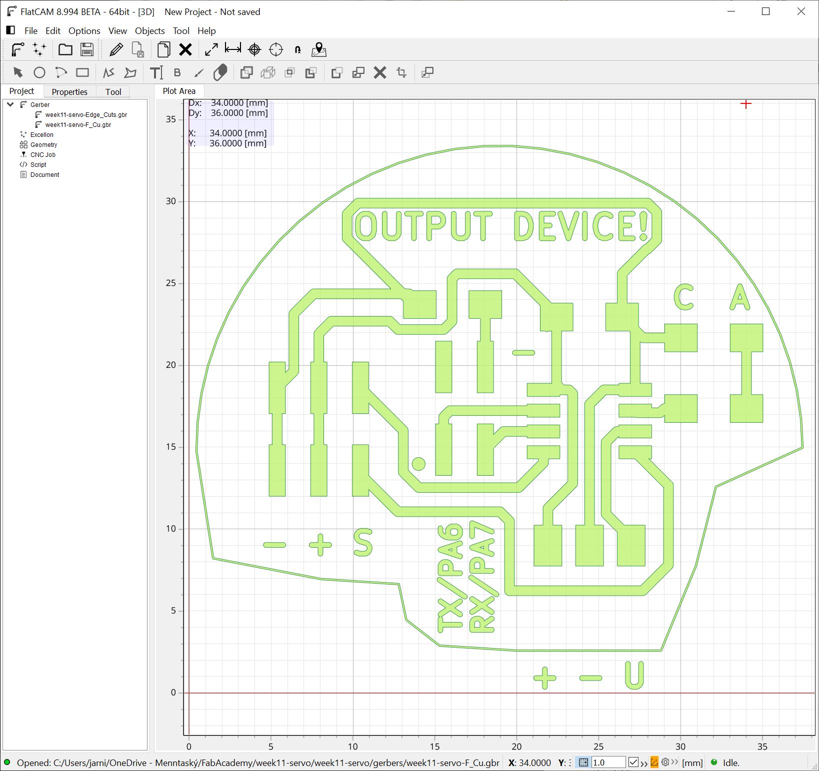
Importing the gerbers
File - Open -> Open gerbers
Select all, open
Setting up the milling
Isolation routing
For the F_cu, double click it and select isolation routing.
Remove the default tool from the Tools table, by right clicking and selecting delete.
Right below that, select Pick from DB!
Select the milling tool you have set up.
Now you see that it’s properties are automatically loaded and the next thing you need to do is to select Generate Geometry.
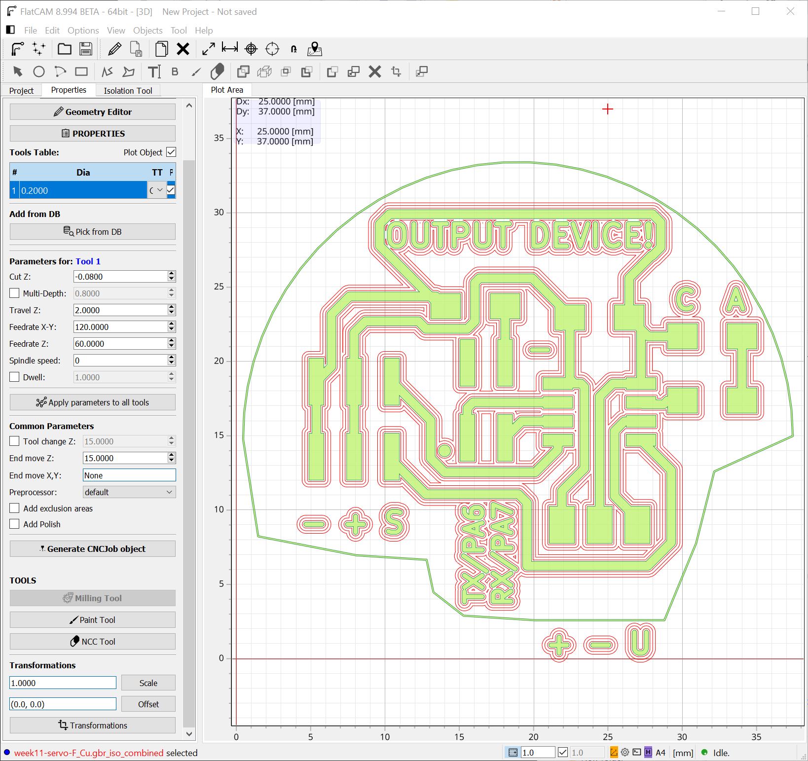
You are now presented with the tool paths. I can see that some of the text will not be completely cut clean, but I’m not worried about that. I can’t see any parts of the actual circuitry that’s not properly isolated. So lets move one!
Now select Generate CNCJob object
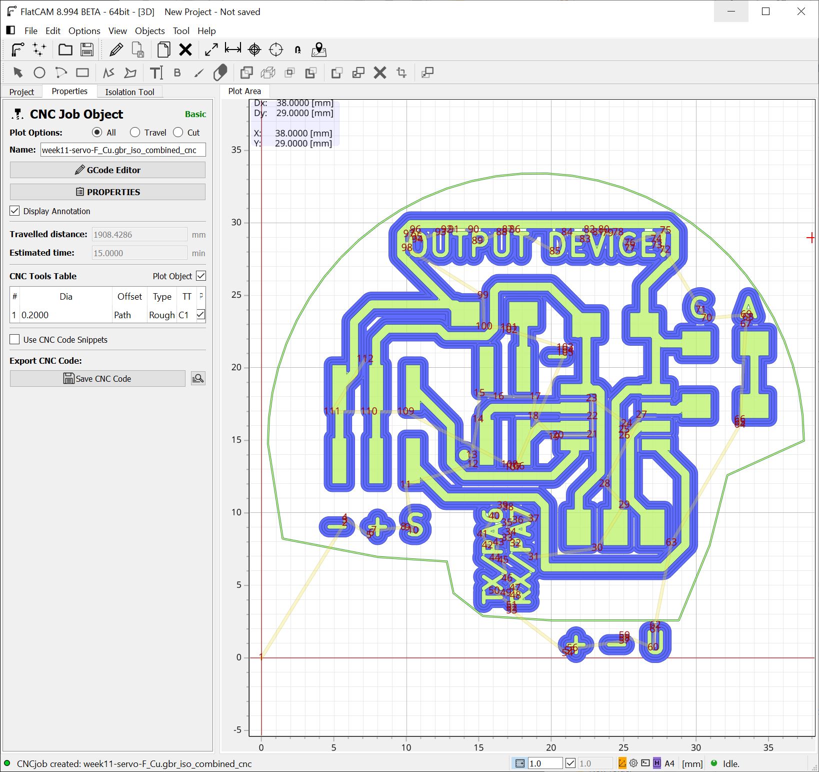
Now you are presented with the this view, all looks well and we can now select Save CNC Code.
Cut-out
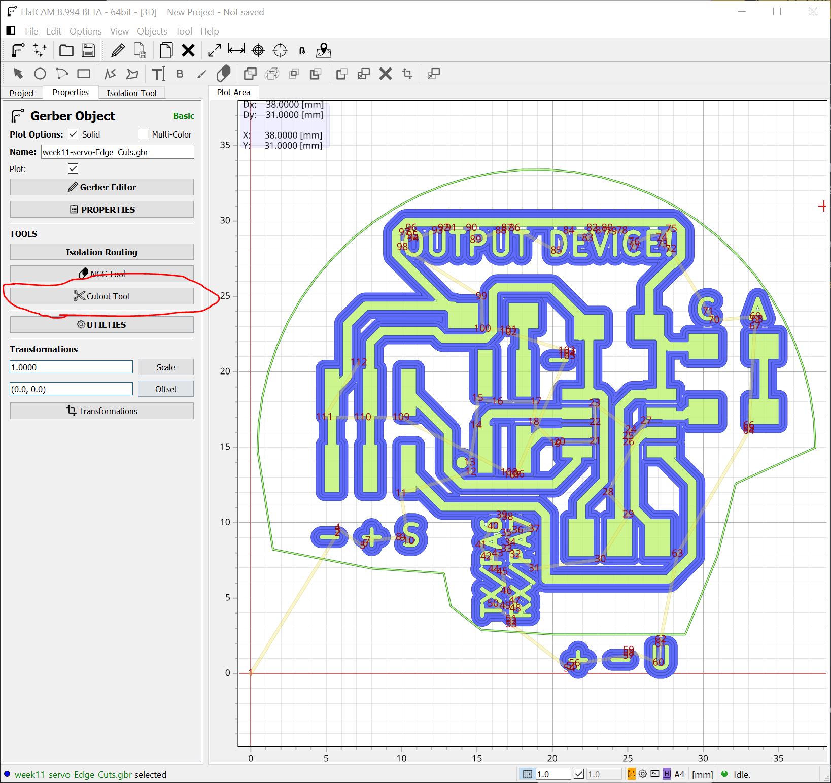
Going back to our main view, by selecting the Project tab, we can select the Edge cuts gerber.
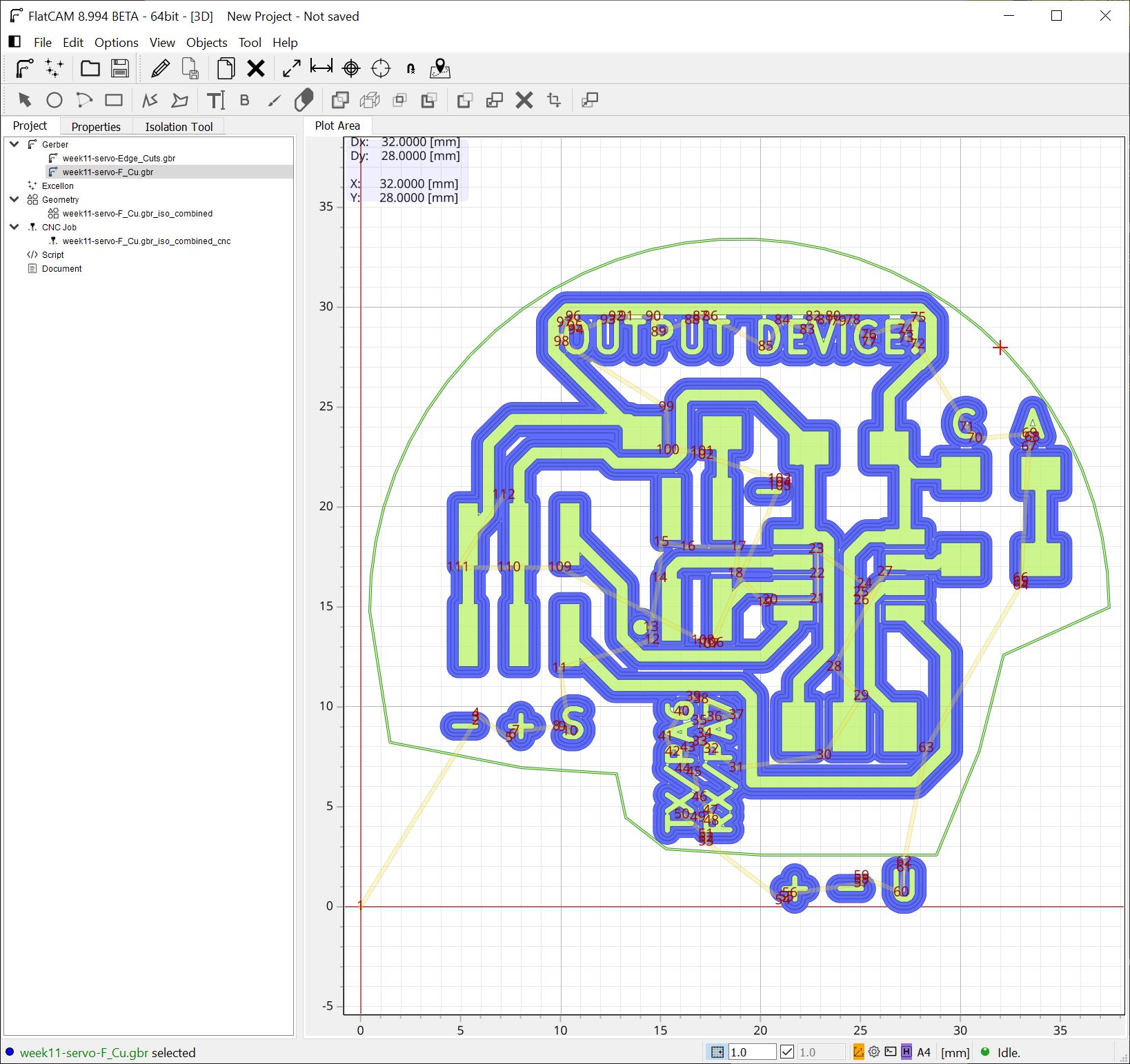
By doing so, we are again selected with the option on how to move forward. This time, we select Cutout Tool.
OOooppps!

I found a mistake! The characters I added below the +, - and U pins are not included in the cutout! I must now go back to KiCad, rectify the mistake and save the file and load it again into FlatCAM!
I have fixed the error and we can continue.
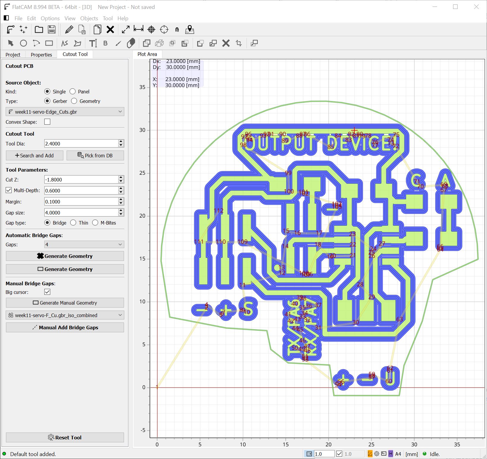
After selecting Cutout Tool, we are presented with a similar view as in the Isolation routing, but with slight differences.
First thing we do, is to select our cut-out tool from the Tools Database, by selecting Pick from DB.
Once the correct tool is selected and we have verified that the tool settings were applied, we must check out the other options.
Make sure you check the Gaps option. They are what in other milling software might be called tabs.
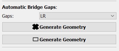
Here I have selected LR, which stands for two gaps one on the (L)eft and one to the (R)ight.
Right below that are two options to generate the Geometry. The one with the X shape, is for irregular shaped boards, while the rectangular one is for.... rectangular boards!
Once you hit the Generate Geometry button, you are not presented with anything… Remember, this software is Beta so its not completely polished.

You must go back to the Project tab and open the Edge cuts file under Geometry
There we simply must select Generate CNCJob object and then Save CNC code like before!
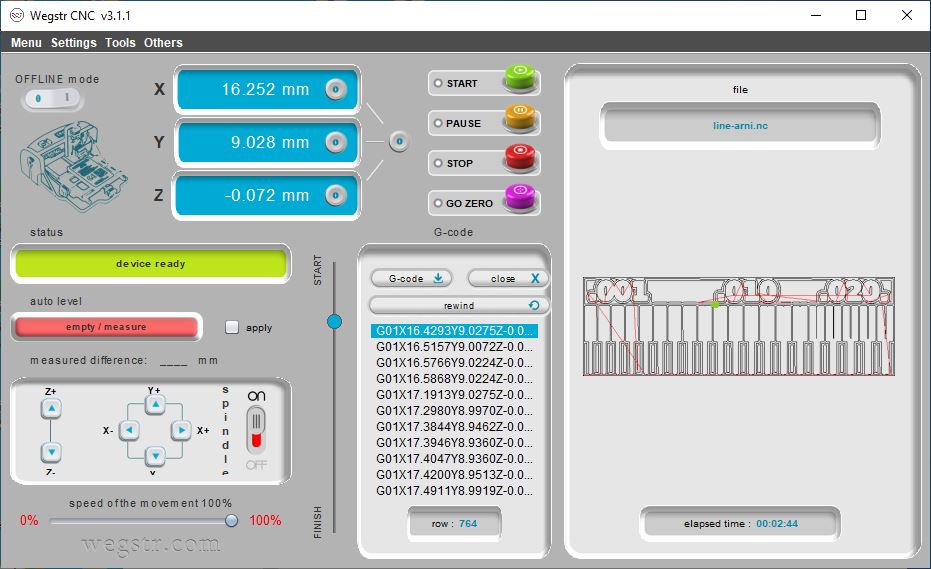
Wegstr
Now that we have both files, we can start milling! As mentioned above, I’ll be using one of two Wegstr CNC machines in our lab.
This is the machine. It needs a bit of cleaning. Let’s do that later, get going with the fun stuff!

Using the tiny hex key provided with the machine, I install the milling bit, which is a V-shaped one.
I manually move the spindle to the lower left corner, as close as I dare, and zero the X and Y axis.
The Wegstr has an auto level feature. You can make it inspect the whole path for the board and it will correct for any misalignment. But that takes time and for a small board like the one I’m milling, I find the basic shortcut usage works well!
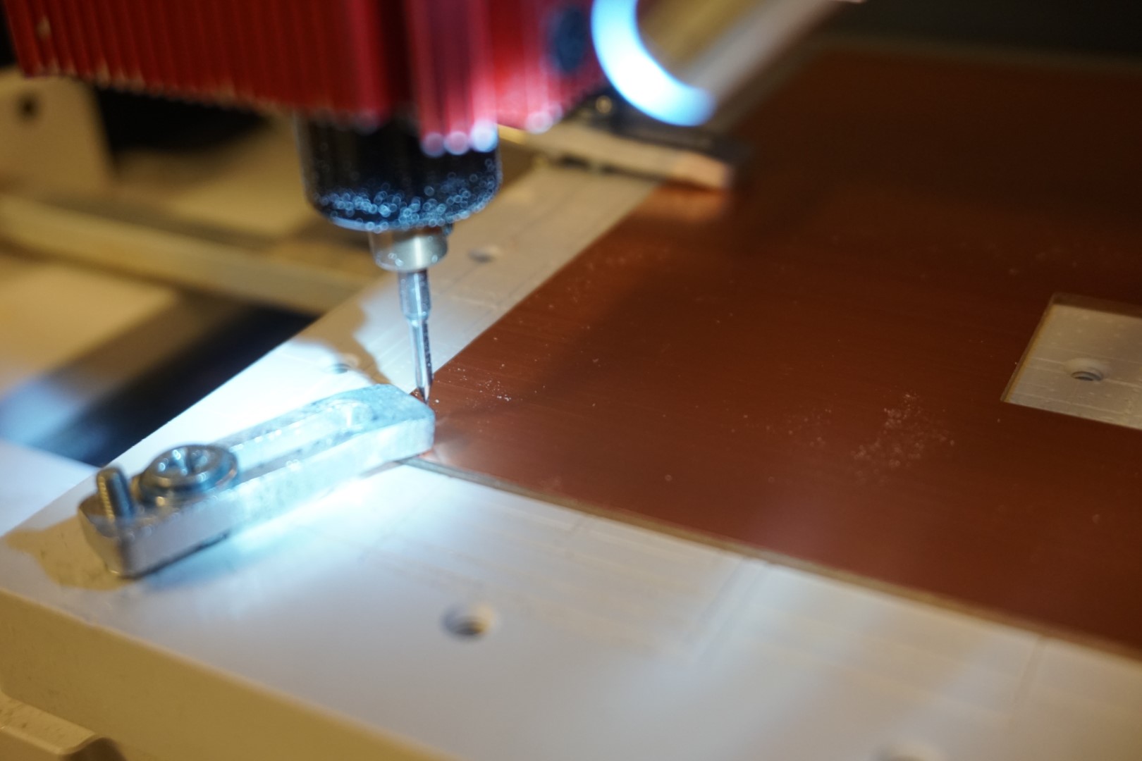
I make sure the lead wire is connected to the PCB, using the aluminum mounting clamps, and simply move the spindle down until the auto level light lights up!
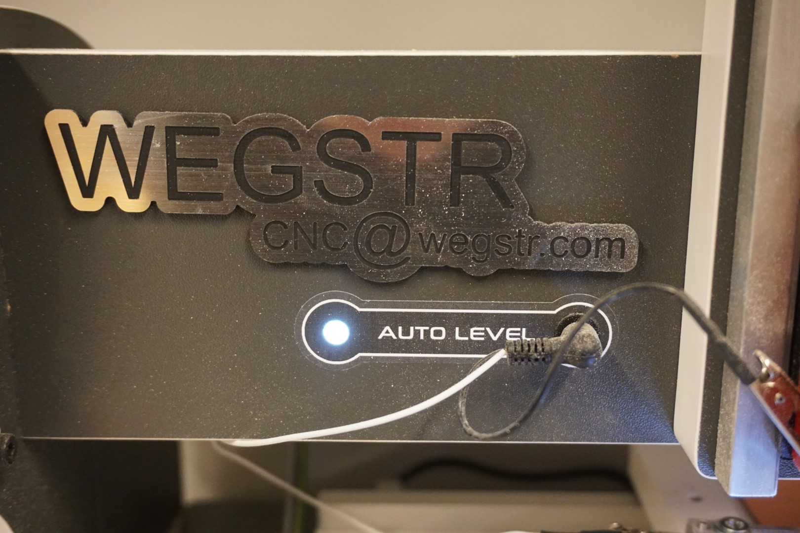
The moment it touches, the spindle stops moving and you have your can zero your Z-axis! Wonderful!

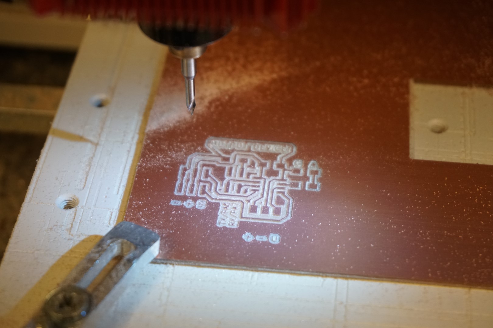
Next up, I load the milling NC file and start the milling!
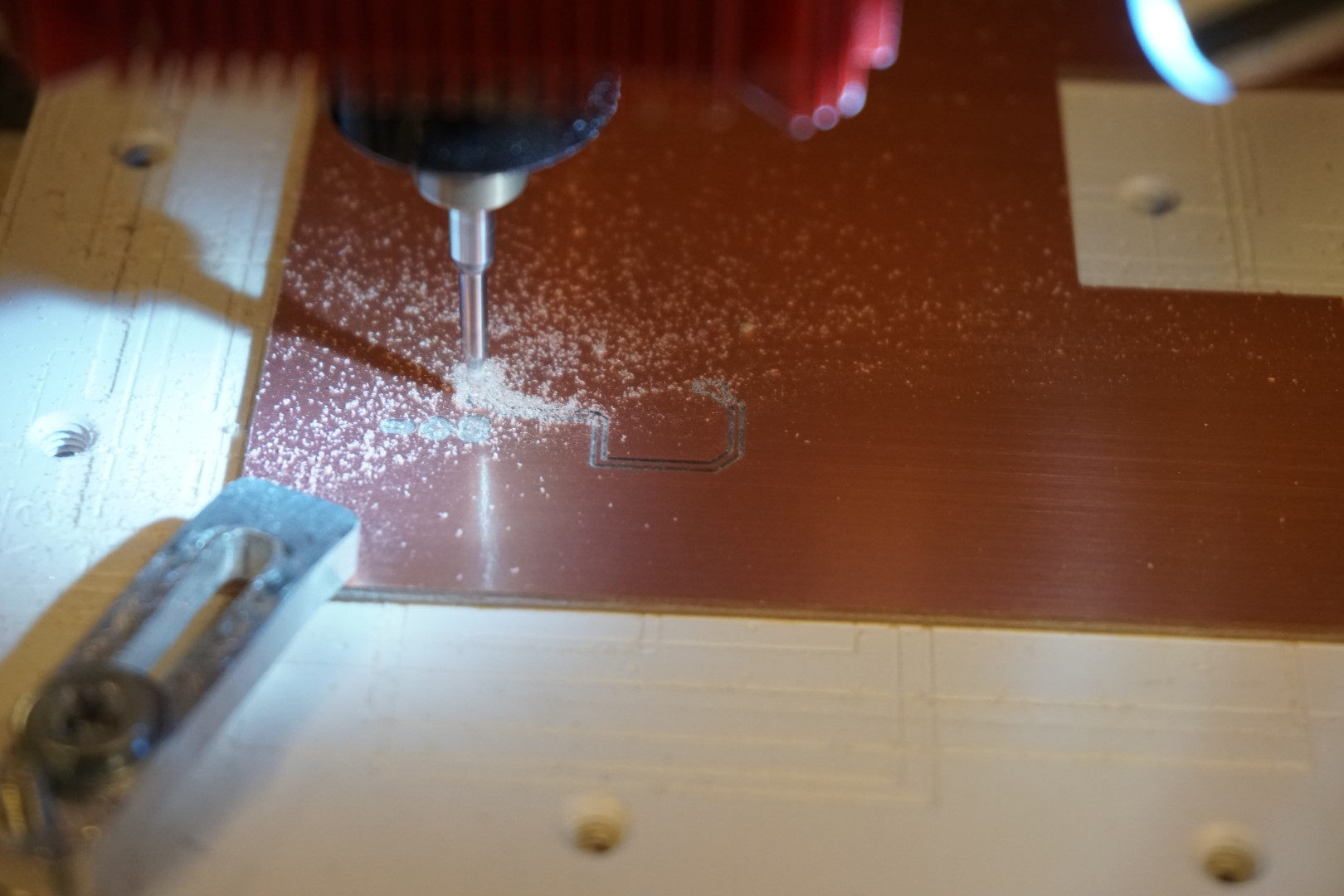
It went well and the traces looks good! It’s not perfect, the letters are not cut clean, but I’m not worried about that.
Next I replace the milling bit with the drill/cutout bit and start the edge cuts NC file.
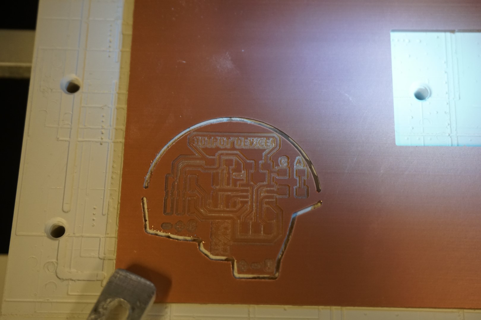
Two tabs, on the left and right, just as planned. Very nice!
Before moving on to soldering, I cut the tabs to remove the board, file the edges, matte the surface finally wash it a bit under running water.
Soldering
Next up, soldering! I like this work.
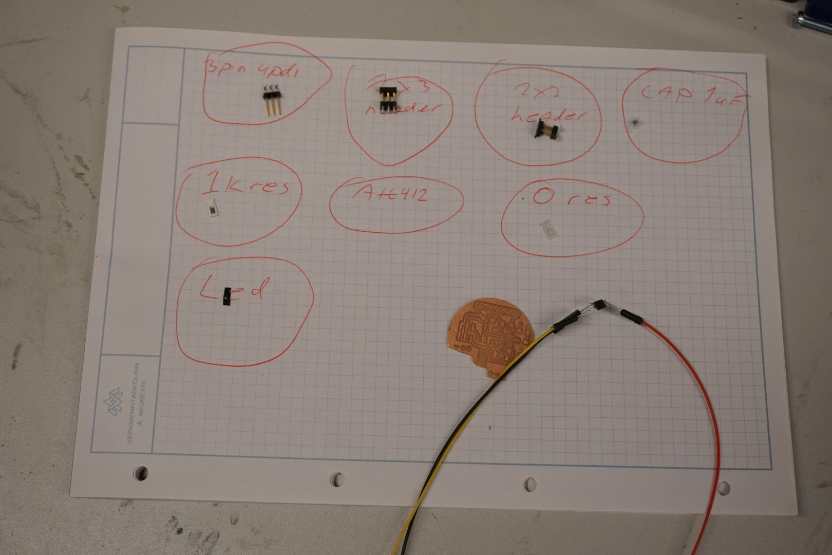
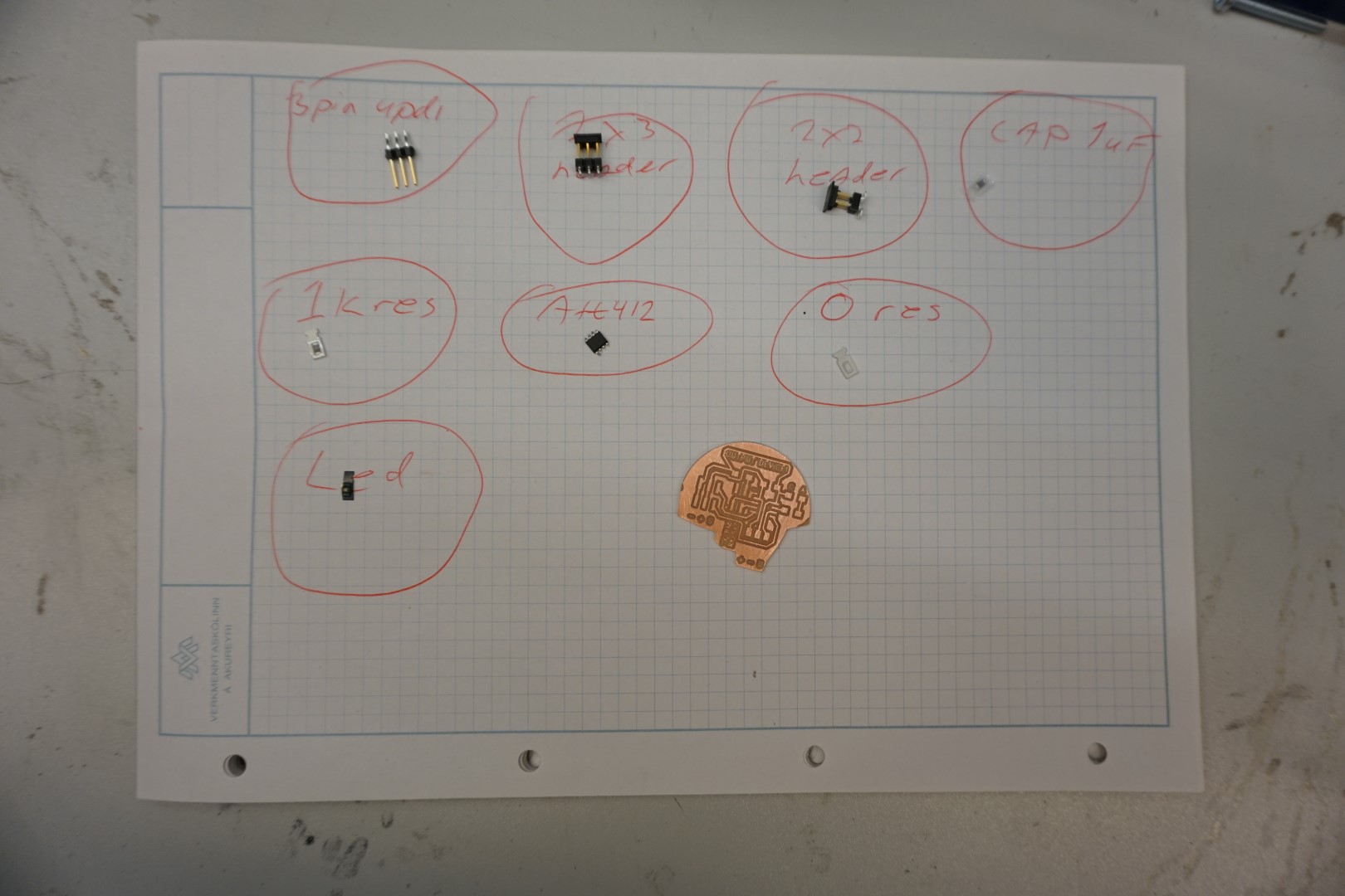
I start by finding all the parts and placing them in their designated circle on my highly technical A4 paper sheet.
I’ll be reusing a ATtiny412 that I used for testing before. I soldered directly to the microchips pins, but removing that was no issue. That way the pins were ‘pre-soldered’ of sorts.
The soldering went well, except I lost focus a bit and soldered a resistor where the LED should be. It would not have made a difference to just leave it and put the LED in it’s place, but it would have been silly to do that since I had marked the anode and cathode on the board!
This was an good opportunity to try desoldering again. This time, I used the gravity method with the hot air gun. Using nice new tweezers, I held onto the resistor and pointed the hot air gun at it. It only took a couple of seconds and the resistor was free with no damage to the board.
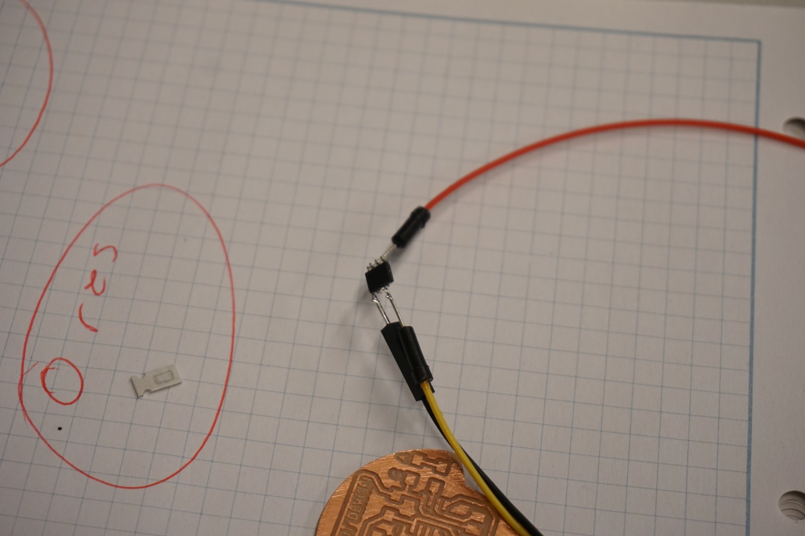
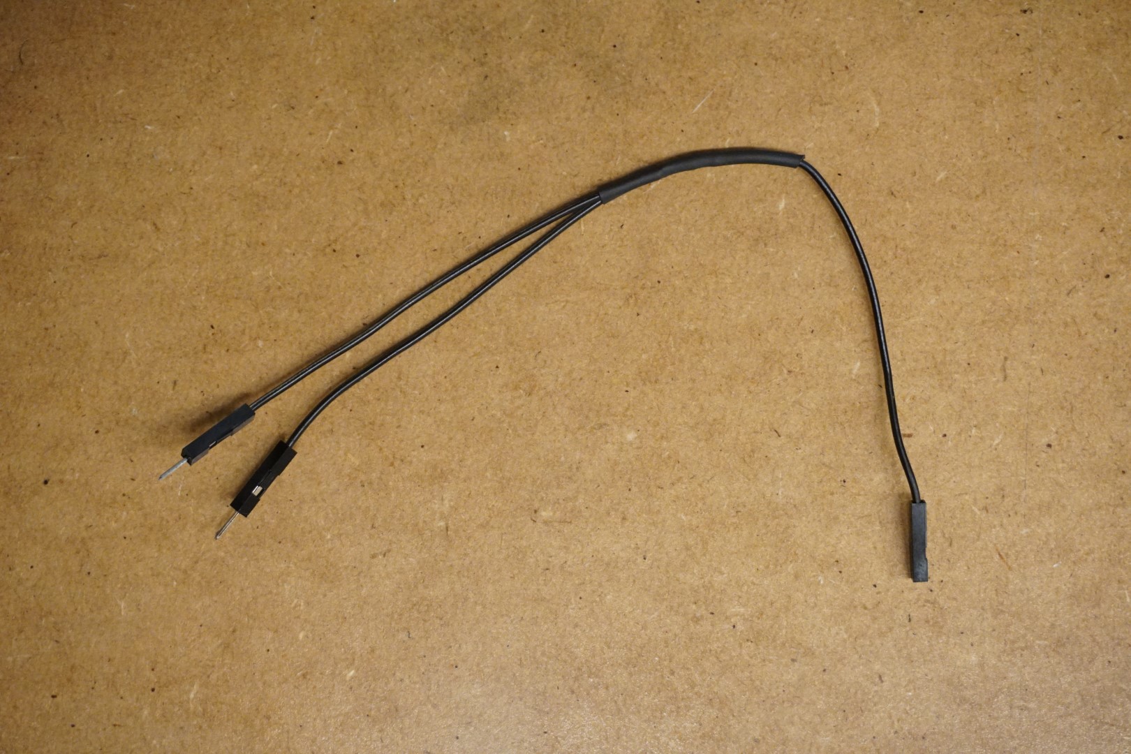
Once I started to use the board, I realized that I should have connected the 4th extra pin to the ground! DUH!
So I made this this y-cable jumper. I included it here, since it’s soldered together =)
Programming
For this board I can use UPDI programming. Again I will be using VSCode with PlatformIO.
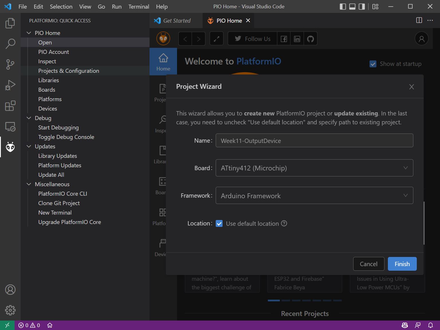
Setup
I create a new PlatformIO project, searching for the ATTiny 412 board:
Once the project is created, I start by recalling the config I used in the previous project:
[env:ATtiny412]
platform = atmelmegaavr
board = ATtiny412
framework = arduino
upload_speed = 115200
upload_flags =
    -d
    attiny412
    -c
    $UPLOAD_PORT
    -b
    $UPLOAD_SPEED
    -v
upload_command = pyupdi $UPLOAD_FLAGS -v -f $SOURCE
I replace the default contents of platformio.ini with the above.
Test code
First thing I do, is to try and flash the diode before moving on.
I write the following code to test the functionality:
#include <Arduino.h>

// Create variable LEDPIN as PA3
const byte LEDPIN = PIN_PA3;
volatile byte LEDstate = LOW;

void setup() {
  // Set pin PA3 as output
  pinMode(LEDPIN, OUTPUT);

  // Set pin PA3 to LOW
  digitalWrite(LEDPIN, LEDstate);
}

void loop() {
  // Turn led on for 1 sec
  digitalWrite(LEDPIN, HIGH);
  delay(1000);

  // Turn led off for 1 sec
  digitalWrite(LEDPIN, LOW);
  delay(1000);
}
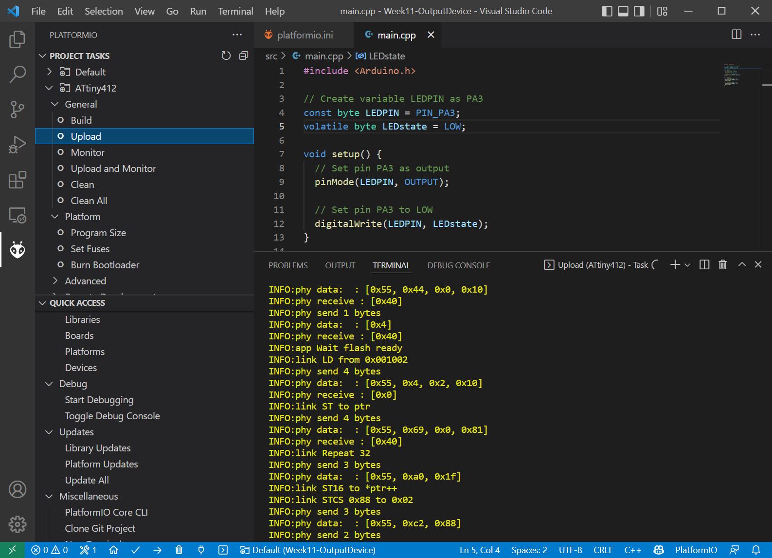
Bulding and uploading
From within the PlatformIO menu, I select the Build option and wait for the wonderful [SUCCESS] message.

Next I select the Upload option and wait while the program uploads. Notice that I do not have to worry about selecting the right port or communication speeds, they are already configured.
Wonderful! It works, the LED flashes nicely
Adding stuff
I found some servos laying around. The color-wiring/pinout is:
| Color | Function |
|---|---|
| Brown | Ground |
| Red | +5V |
| Yellow | Signal |
I add two of them to the board, shown in video below.
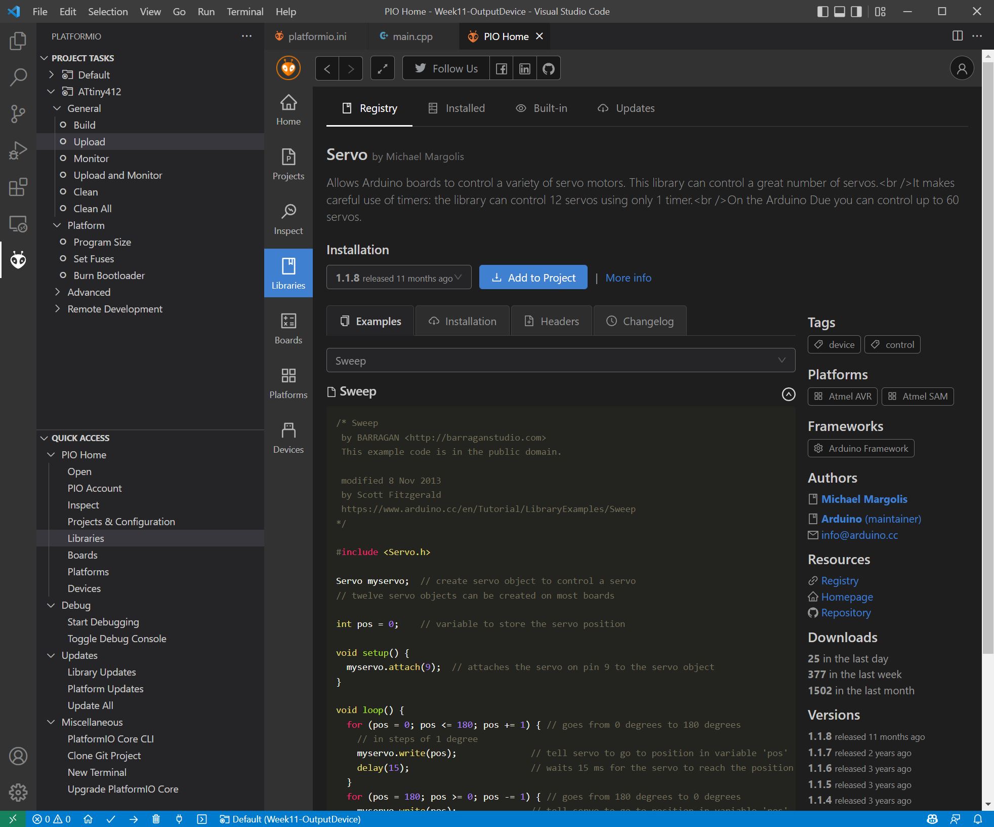
I want to use the Servo library for the project. To add it with PlatformIO, I go the the Libraries tab under Quick Access and search for Servo.
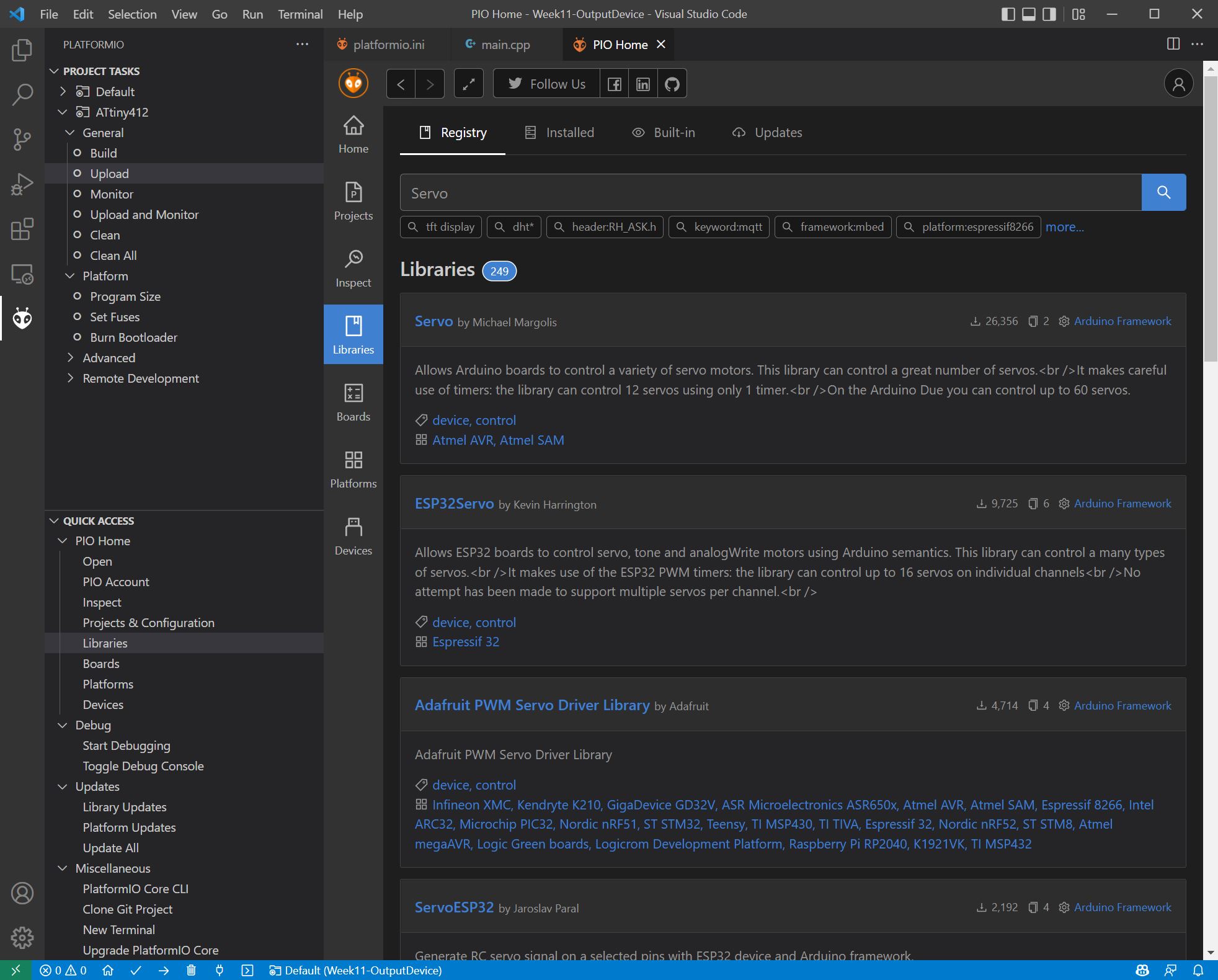
The top result is a popular one, so I select it. The next window tells me more about the library, gives me examples and the option to add it to the project. I do that.
In the following dialog, you must select the correct project and select Add.

It takes a moment to install and a popup notifies you that the library is installed (or failed, mine was a success).
Going back into the platformio.ino file, we can see this added to it:
lib_deps = arduino-libraries/Servo@^1.1.8
At the top of my main.cpp file, I add:
#include <Servo.h>
Next I update the code to incorporate the two servos:
#include <Arduino.h>
#include <Servo.h>

// Create variable LEDPIN as PA3
const byte LEDPIN = PIN_PA3;
volatile byte LEDstate = LOW;

// Set up the servos
Servo servo1;
Servo servo2;

// Set up the servo pins, PA1 and PA2
const byte servo1Pin = PIN_PA1;
const byte servo2Pin = PIN_PA2;

// Set up variables for the servo positions
int servo1Pos = 0;
int servo2Pos = 0;

// Set up the servo positions
const int servoMin = 0;
const int servoHalf = 90;
const int servoMax = 180;

void setup() {
  // Set pin PA3 as output
  pinMode(LEDPIN, OUTPUT);

  // Set up the servos
  servo1.attach(servo1Pin);
  servo2.attach(servo2Pin);

  // Set the servo positions
  servo1.write(servo1Pos);
  servo2.write(servo2Pos);

  // Set pin PA3 to LOW
  digitalWrite(LEDPIN, LEDstate);
}

void flash(){
  // For loop for 10
  for (int i = 0; i < 10; i++) {
    // Toggle the LED state
    LEDstate = !LEDstate;
    digitalWrite(LEDPIN, LEDstate);
    delay(50);
  }
}

// Moves the servos, just for display
void servoFun(){
  servo1.write(servoHalf);
  servo2.write(servoHalf);
  delay(500);

  servo1.write(servoMin);
  servo2.write(servoMin);
  delay(500);

  servo1.write(servoMax);
  servo2.write(servoMax);
  delay(500);
}

void loop() {
  // Flash led
  flash();

  // Move servos
  servoFun();
}
Trouble!
Now I ran into some trouble! When building the program I got the following error:
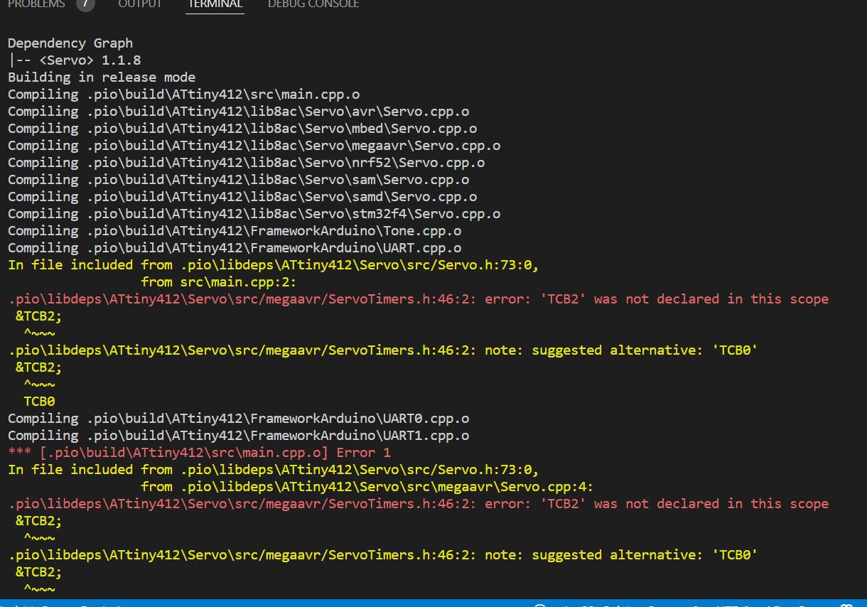
This seems to indicate some sort of trouble regarding the internal clock or something.
After spending some time trying to rectify it, I decided to try to upload the code using Arduino IDE.
I double check the Library manager, which confirms that the same library is installed (1.1.8).
Going back to VSCode, I looked at the servo header and cpp files, modified some code, but could not get the servos moving even though I got rid of the previous errors.
WEIRD!
As this point I can’t spend more time on this error, so I just use Arduino IDE to upload the code.
Moving on.. now with lasers!
Anyways, this works well.
I found an laser module, KY-008. It’s simple, just + and - so I add it to one of the extra pins.
Since I just put one ground pin, I soldered the Y-shaped cable, pictured above, to be able to connect two grounds.
Adding pin PA6 as the laser pin to the code, I can now fire a laser!
Sharks with frickin laser beams
Next step was obvious, attaching the laser module to the servo arm!
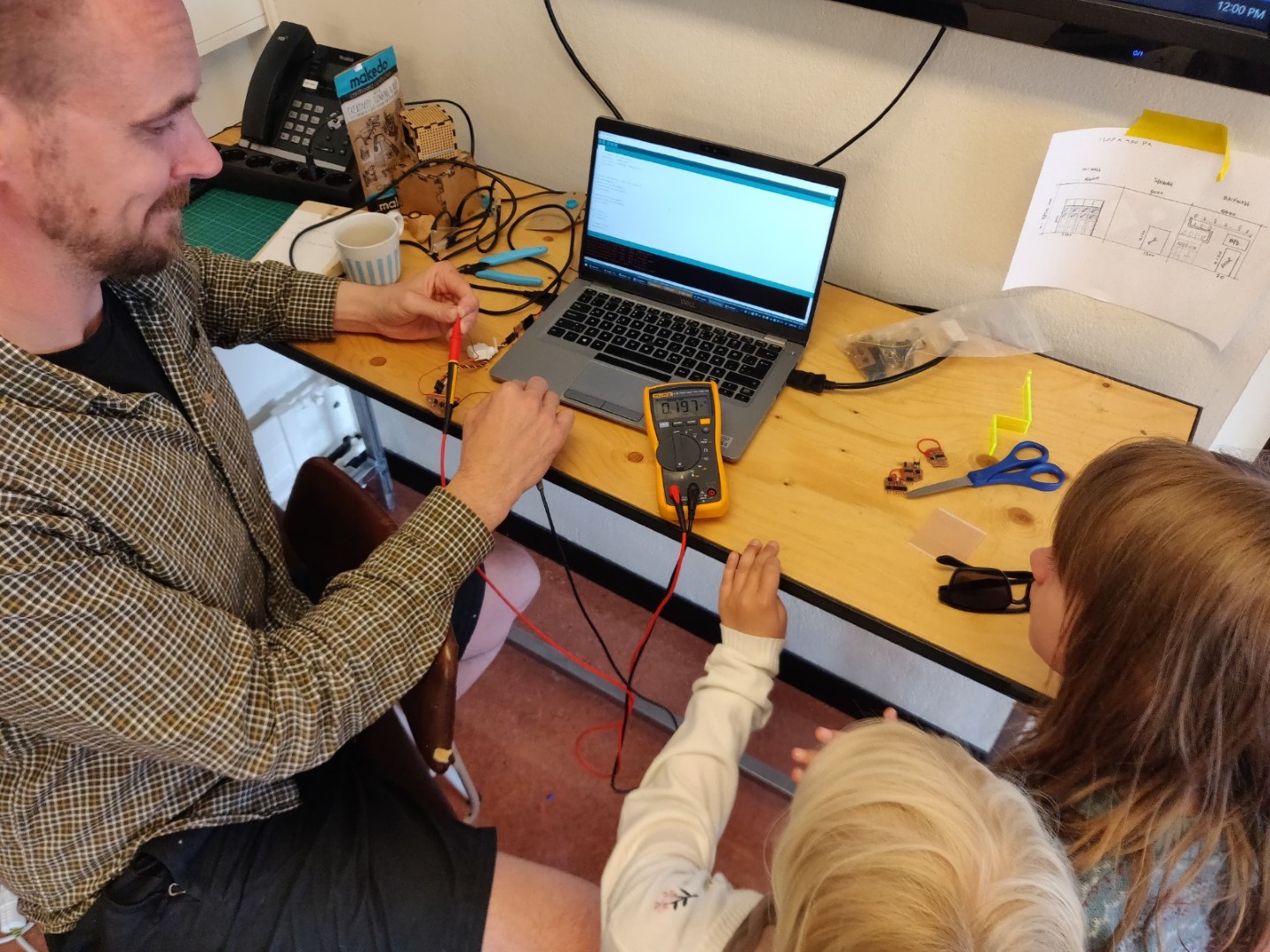
Measuring current
Final thing to do is to measure the current usage. You can do that by severing the power supply and connecting a multimeter in serial, passing the current through it, described below:
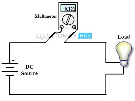
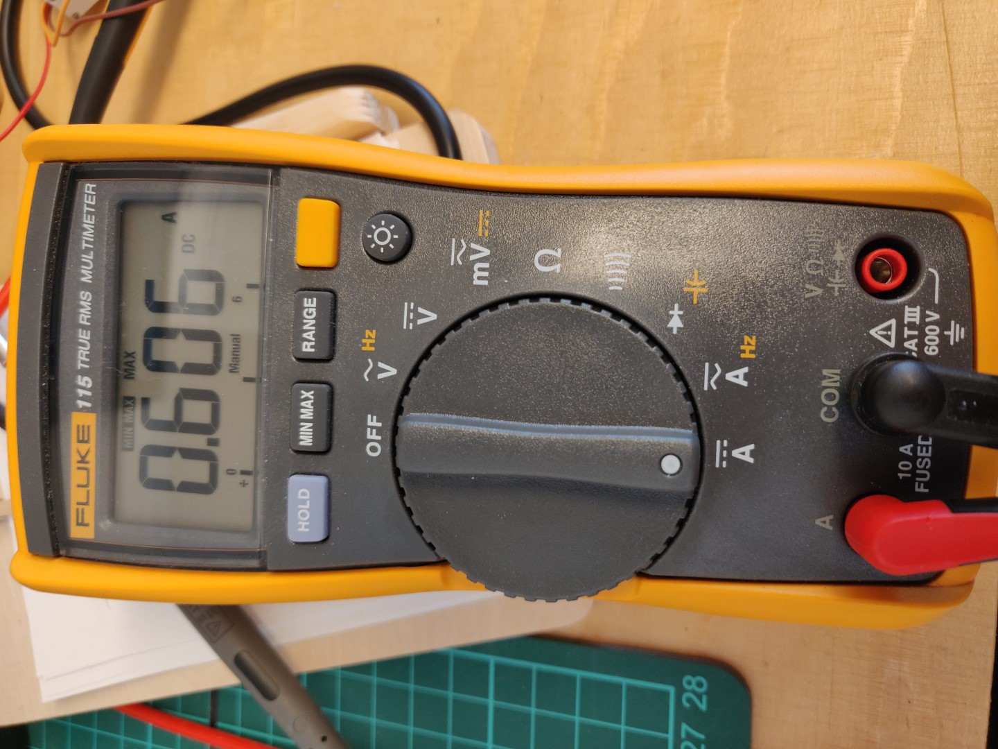
Notice the connections on the bottom, the setting which the selection wheel is set on and the MIN MAX button. The MIN MAX button is very handy, since in this case, the servo is only active for a rather short time, we can set it to the MAX and it captures displays the highest load value captured.
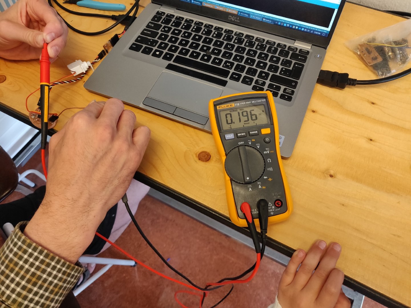
I decided to measure the power usage of the servo, since I figured it would be the highest currant using device. I accidentally cut both the negative and positive wires, so I just measured both, there was no difference. But normally you should position the multimeter before the load (servo, light, or whatever you are measuring).
You must also connect the leads to the multimeter correctly. The red one, positive, should go into the A(ampere) slot and the black, negative, should go into the COM port as usual.

You then connect the load, making sure to make the positive lead face the supply and the negative face the load, this gives you the correct output.

Running the code, which just moves the servo and waits for second before moving it again, we get the measurement: ~0.2 A
Two little ladies followed my every step, very interested!
I then added more load the servo, by holding the servo back with my fingers, creating more resistance. This tripled the current consumption!
Wonderful!
Conclusion and troubles
I made a couple of small mistakes this week, but nothing big.
I did spend some nice time trying out KiCad more and I’m getting comfortable with it. Next thing I’d like to try is to use the entire board as a ground. That might make things simpler, at least in certain cases.
Software / library troubles.
I had some troubles with the software libraries, from what I can see is that they might not support the chip? I’m not sure.
Biggest trouble
I caught the seasonal influenza and I’ve been pretty much knocked out for the last days.