8. Computer-Controlled Machining
This week is about making something big. I’ll use the software and other tools and techniques needed for large format production.
Safety first!
I’m already familiar with working with heavy machinery and the inner workings of our FabLab. But I’d like to iterate on a couple of items that are very important to me.
Sweep the floor!
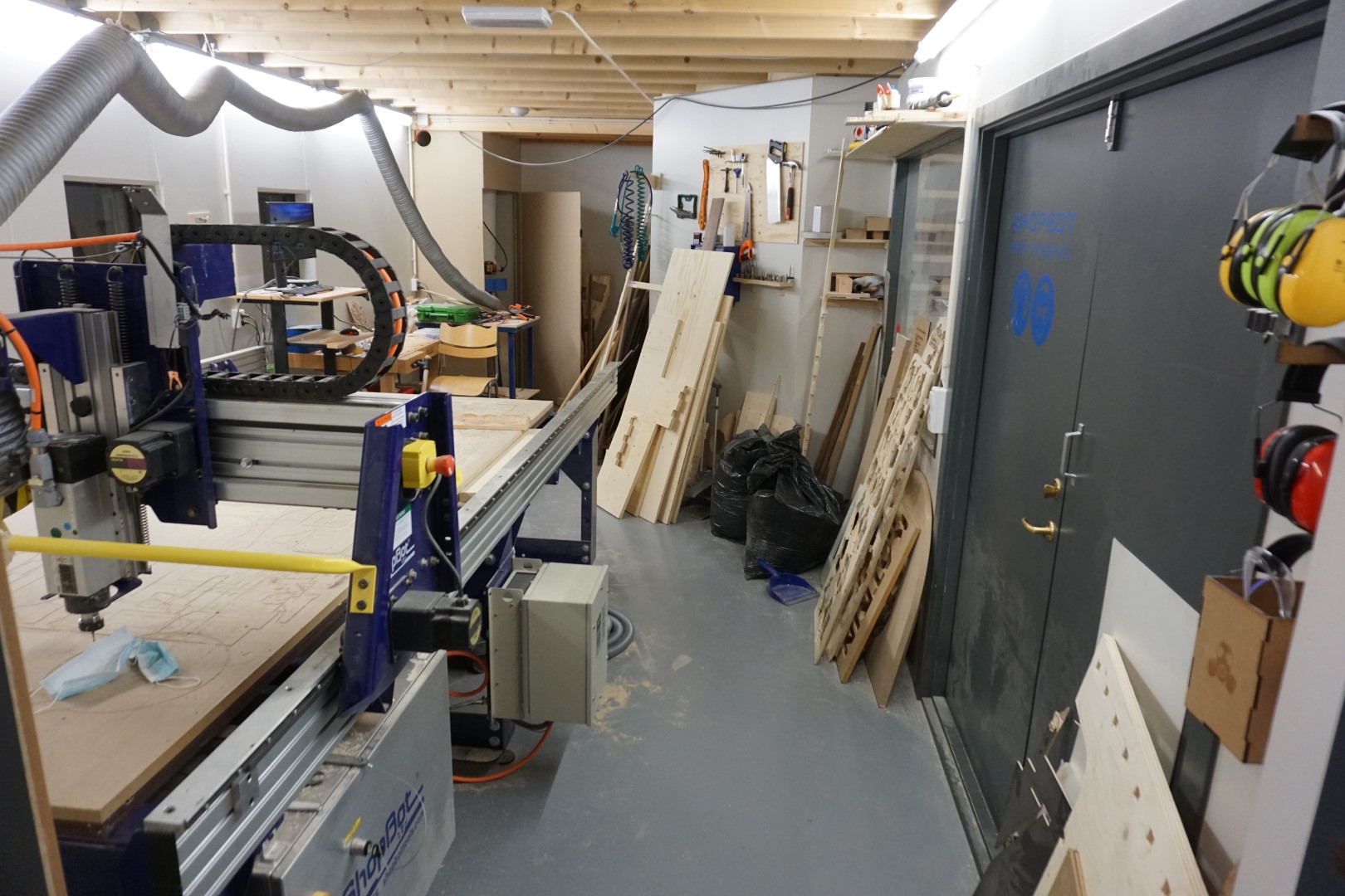
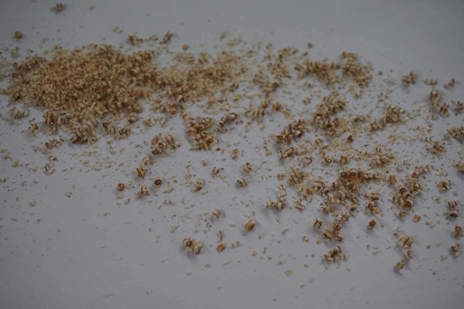
Dust is slippery and falling can have horrible consequences. So if your floor looks like this:
sweep it and it will look something like this:
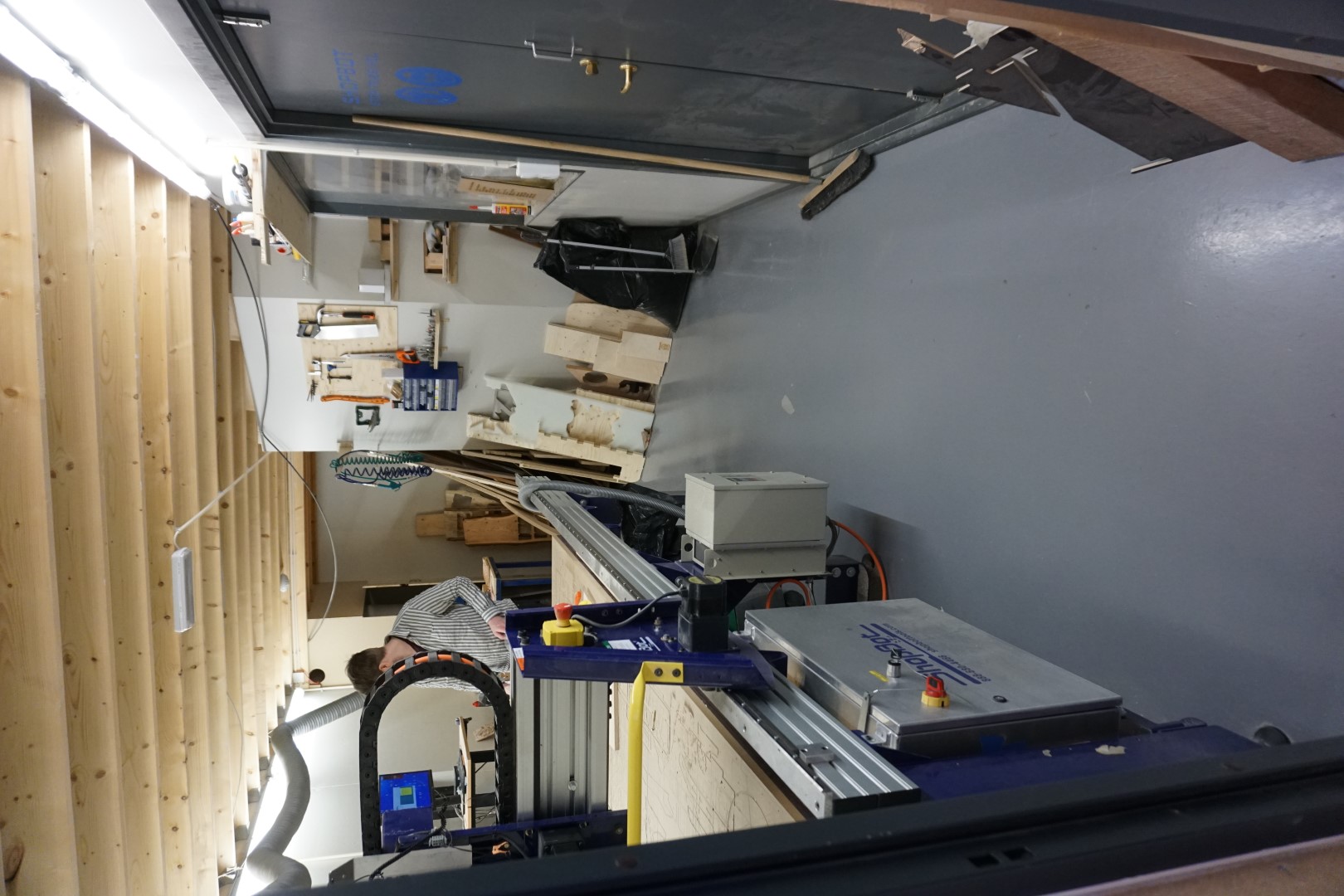
This is better. But it’s not perfect. This room needs better cleaning and storage. The space is also very limited, but that will not be solved this week.
PPE
Personal Protective Equipment (PPE) is a set of items that are used to protect you from hazards.
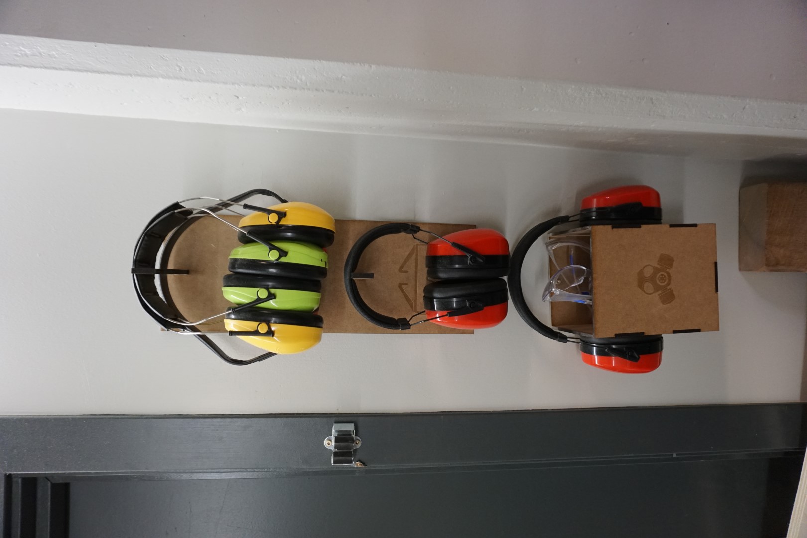
Here we have ear and eye protection. Wearing gloves when handling the material is also recommended, but make sure that you take them off when milling, since you do NOT want it getting caught in the spindle (same goes for hair, sleeves, ties, necklaces!). We have industrial suction for the Shopbot but wearing a mask can be a good idea in certain cases.
Hard emergency stops and software stops
On the machine there is a button that will stop the machine if you press it. These buttons should always be easily accessible and staying close to them while working is a must.
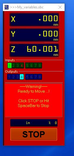
On the Shopbot software there is a button that will stop/pause the job if you press it. Hovering the spacebar/mouse over the button is good, especially if there is something that you suspect might go wrong. The good part of that, is that it saves the state of milling and you can continue where you left off if you are able to.
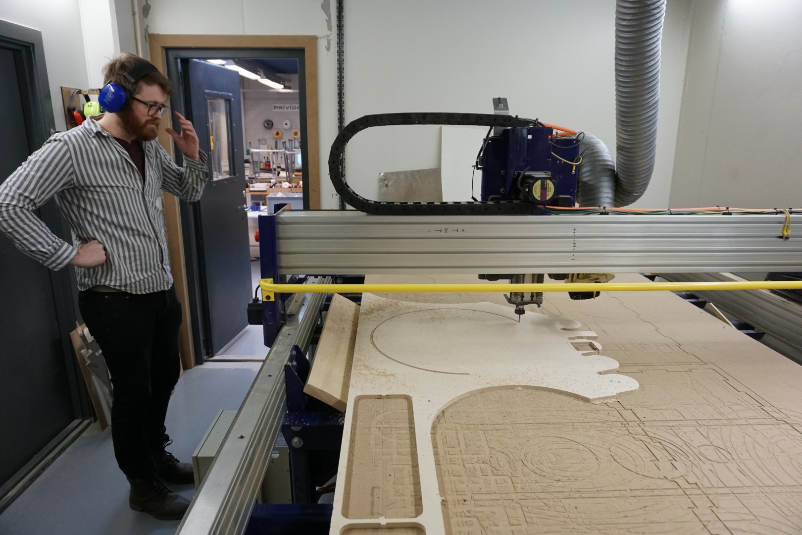
Acquaiting myself with the Shopbot
This is our Shopbot. It includes a homemade tool to ease ascension and descension of users, especially when carrying heavy materials.
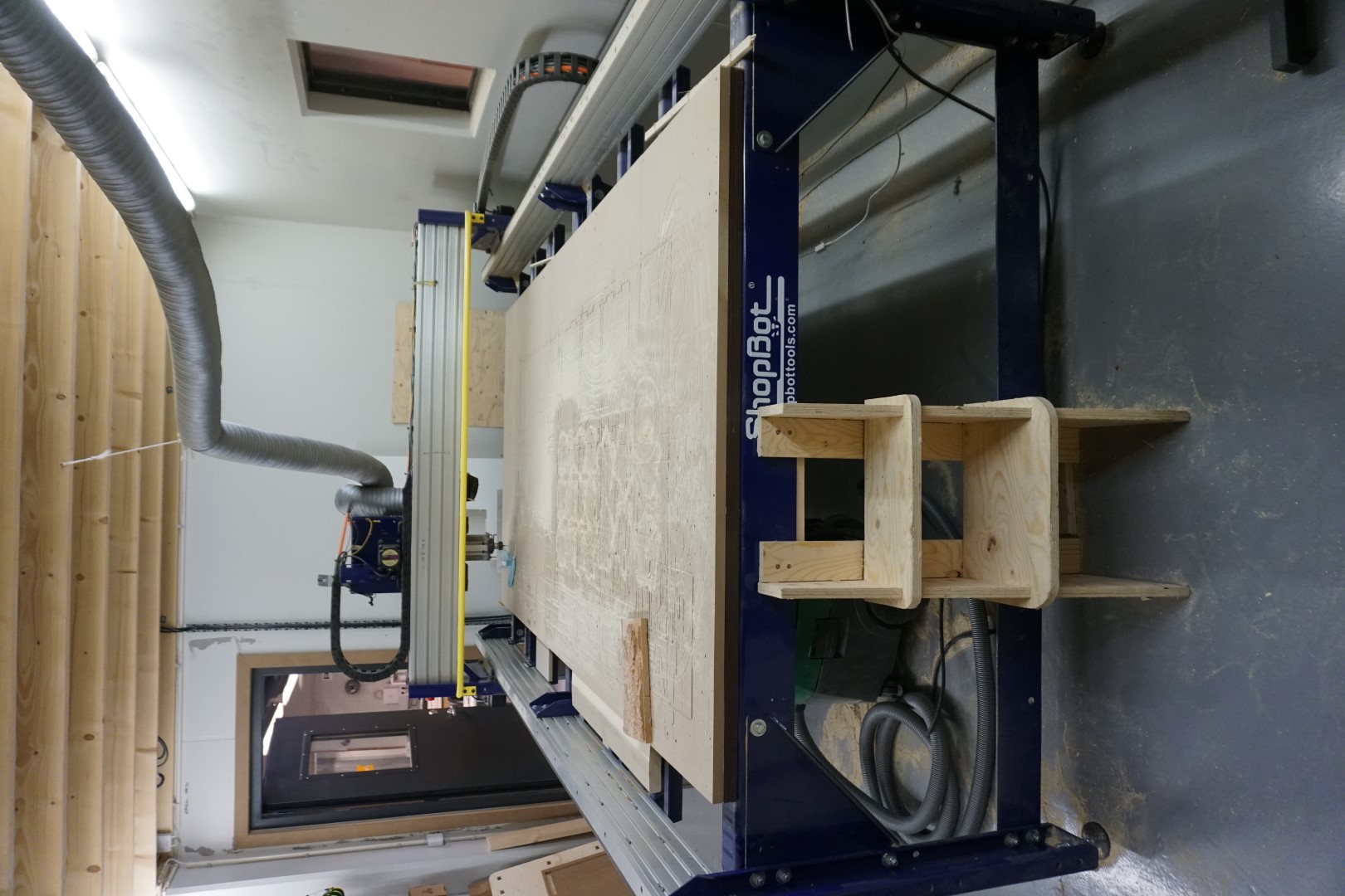
I’ve just used the Shopbot a little bit. So this week should prove to be a good learning experience.
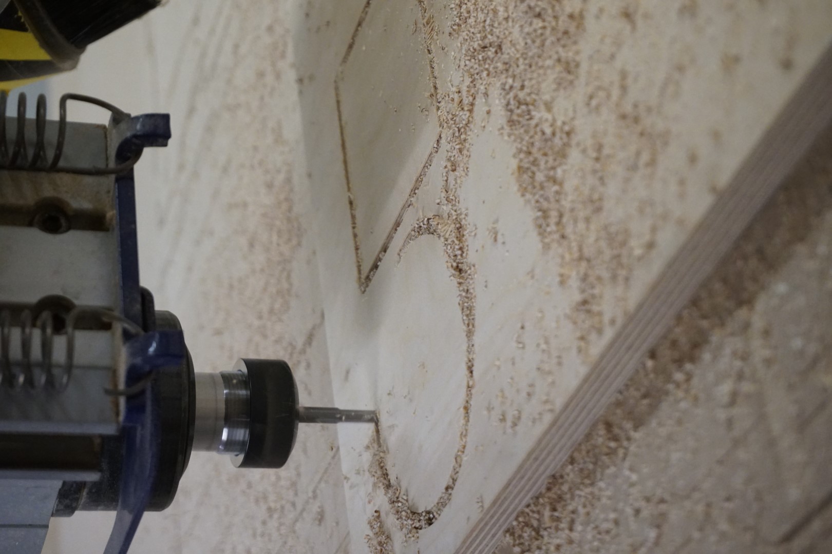
First thing I wanted to do is to create a CNC job with a square and a circle. I’ll be using birch plywood, with a relatively few layers. This is leftover material and thus cheap to practice with.
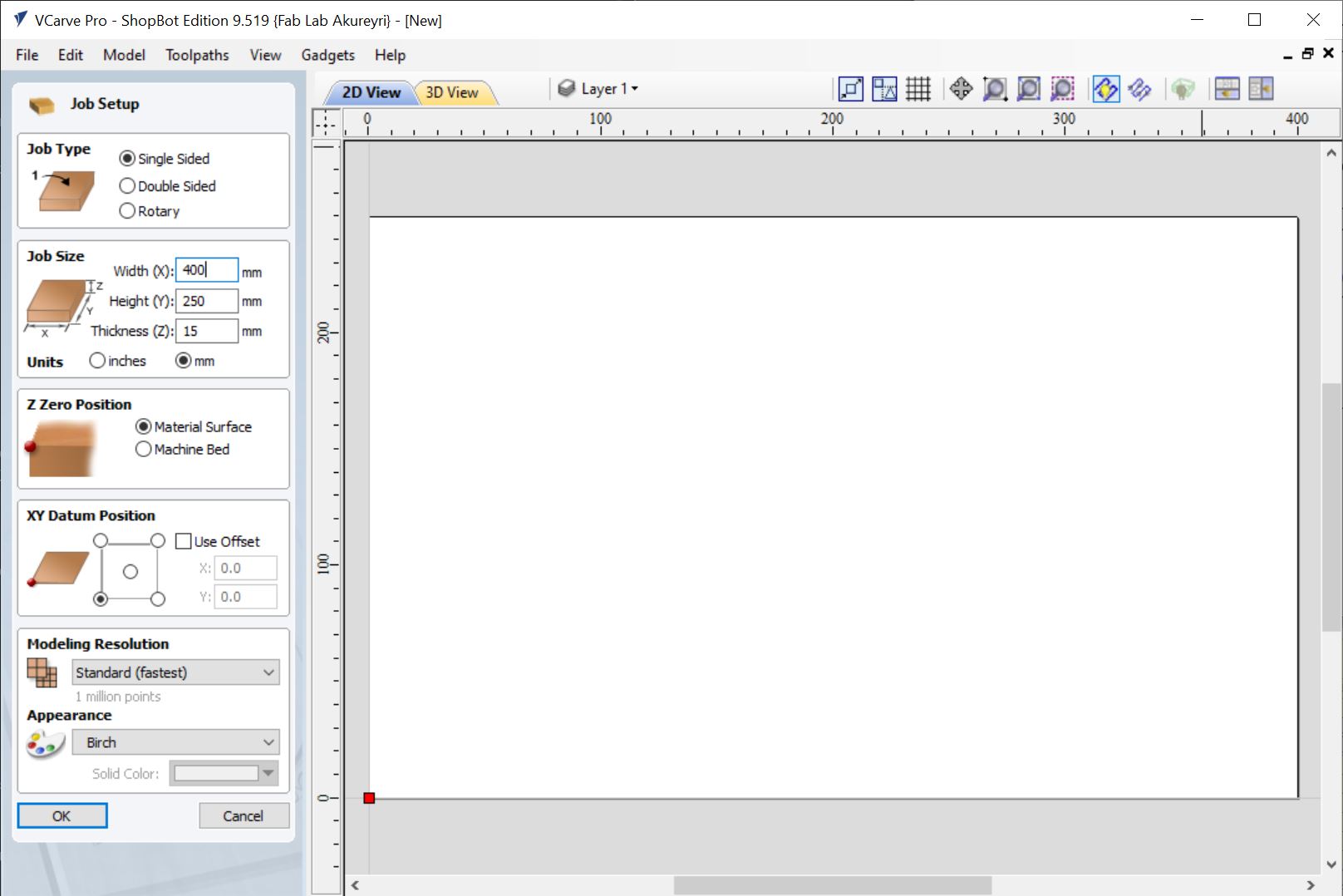
VCarve is not a free tool but we have it here in the Fab Lab. First thing to do is to set up the project. My piece of wood is 15mm thick. The work area is about 250mm x 40mm. I input these values into the VCarve project.
Design
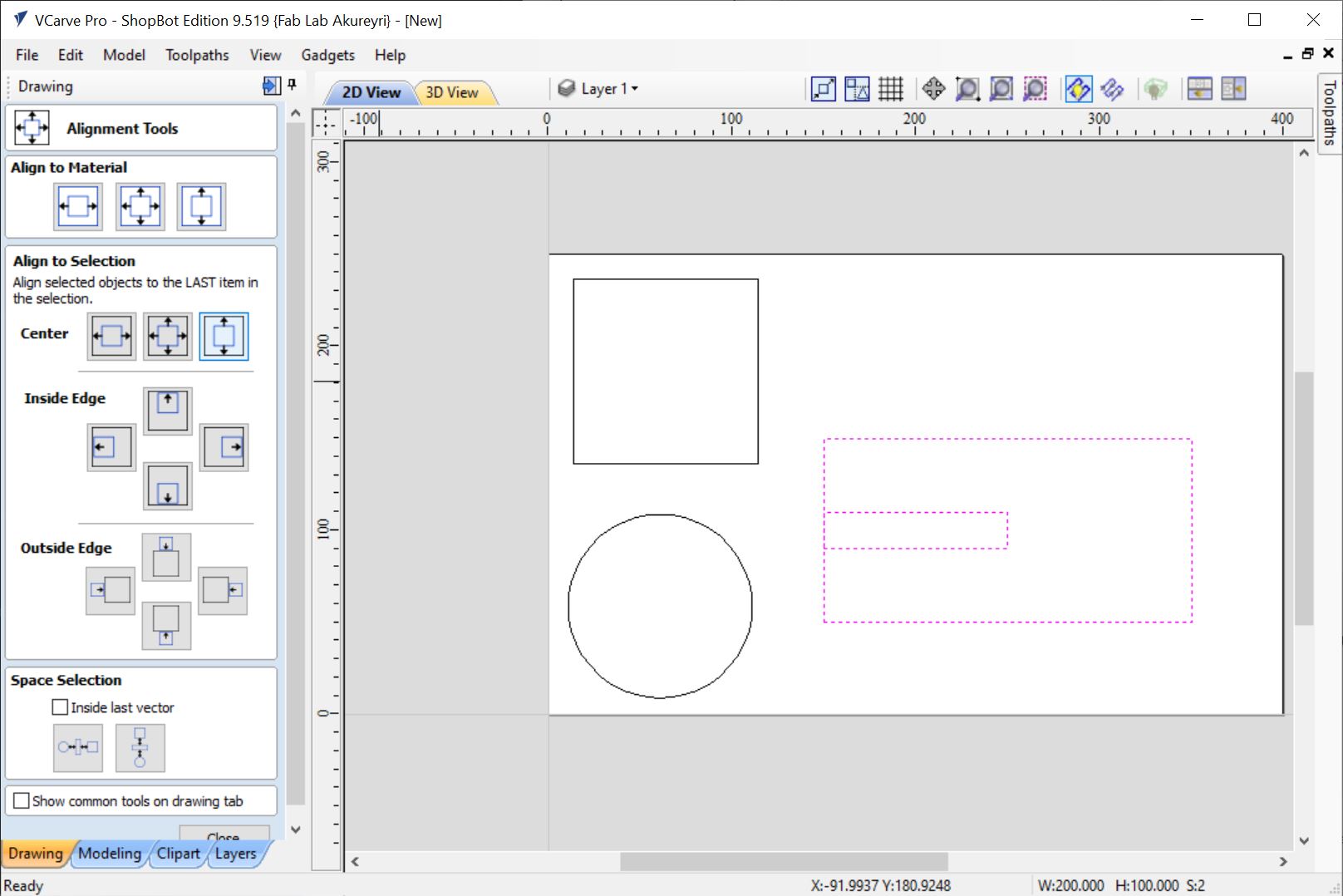
I then created a couple of items, a ring and a square, both of size 100mm. Once I had placed them, I thought I’d like to get more use out of this piece of wood and wanted to add a dogbone test piece.
I created a another box and a smaller box within that box. The smaller one would act as the slot to join the pieces.
Using the align tool, I centered the smaller one on the box and aligned it to the left.
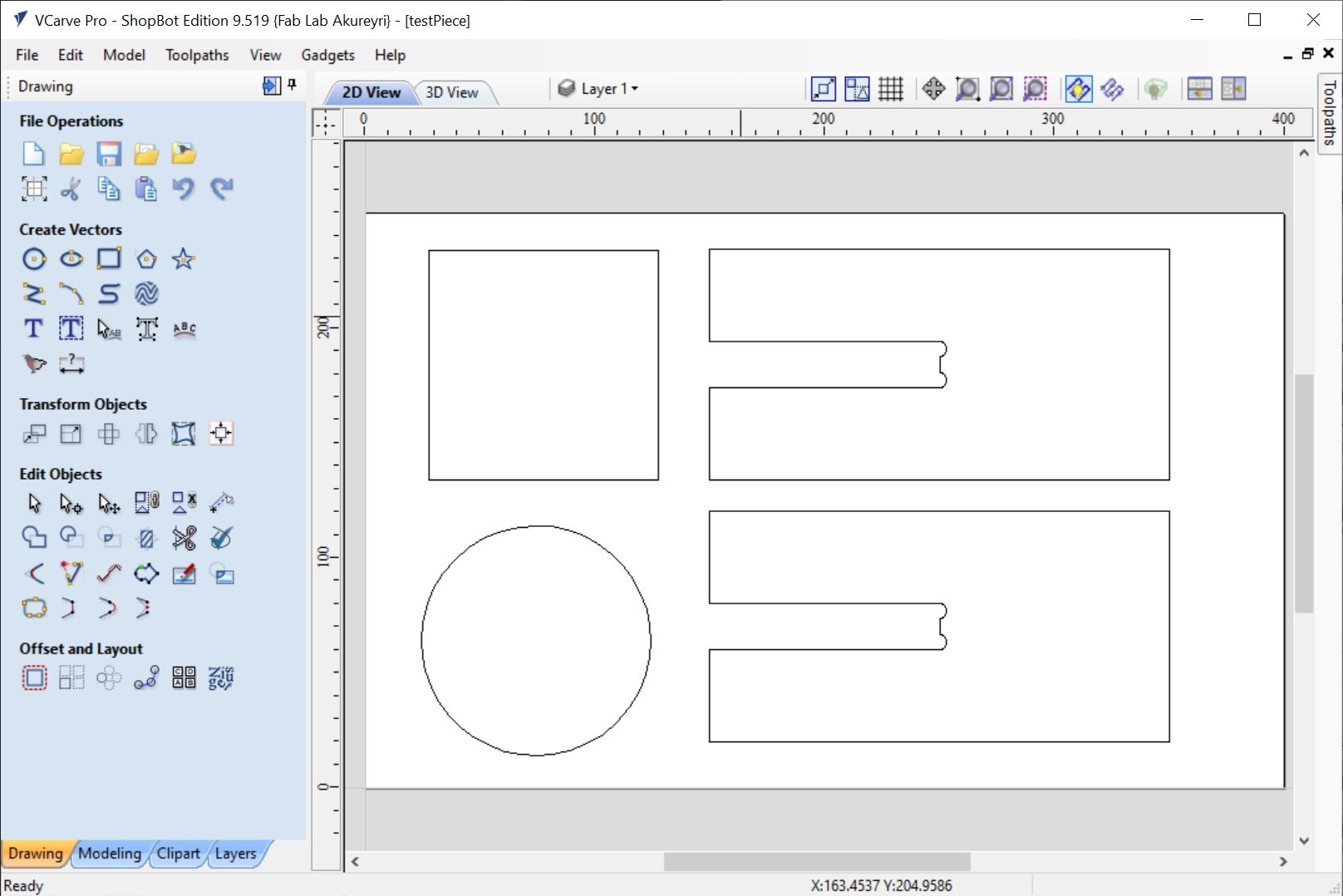
I then used the subtraction tool to cut it out of the larger box, then added a dogbone to the corners. Then I duplicated the object to create the second part.
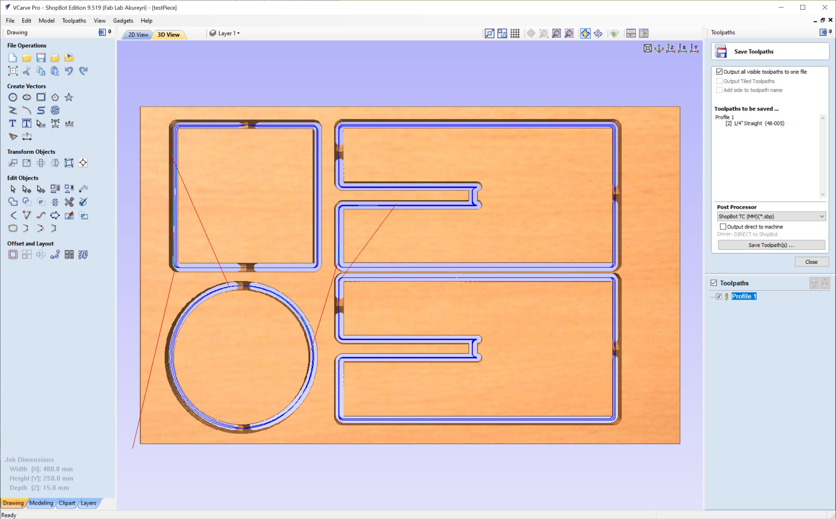
Toolpaths
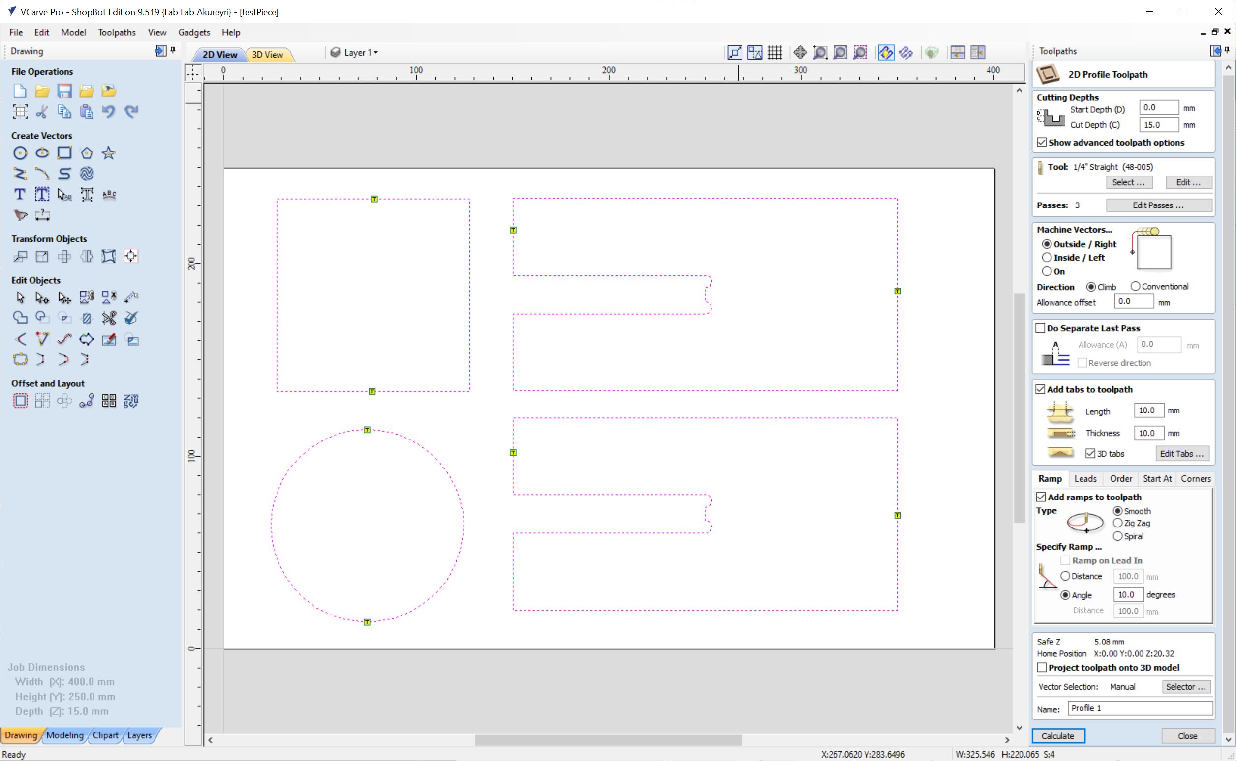
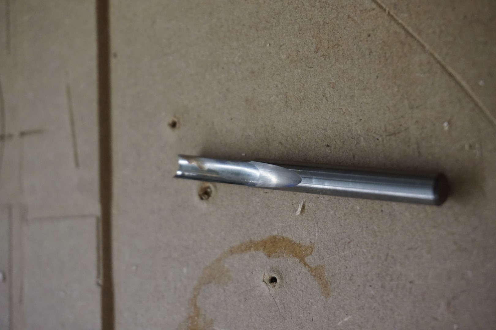
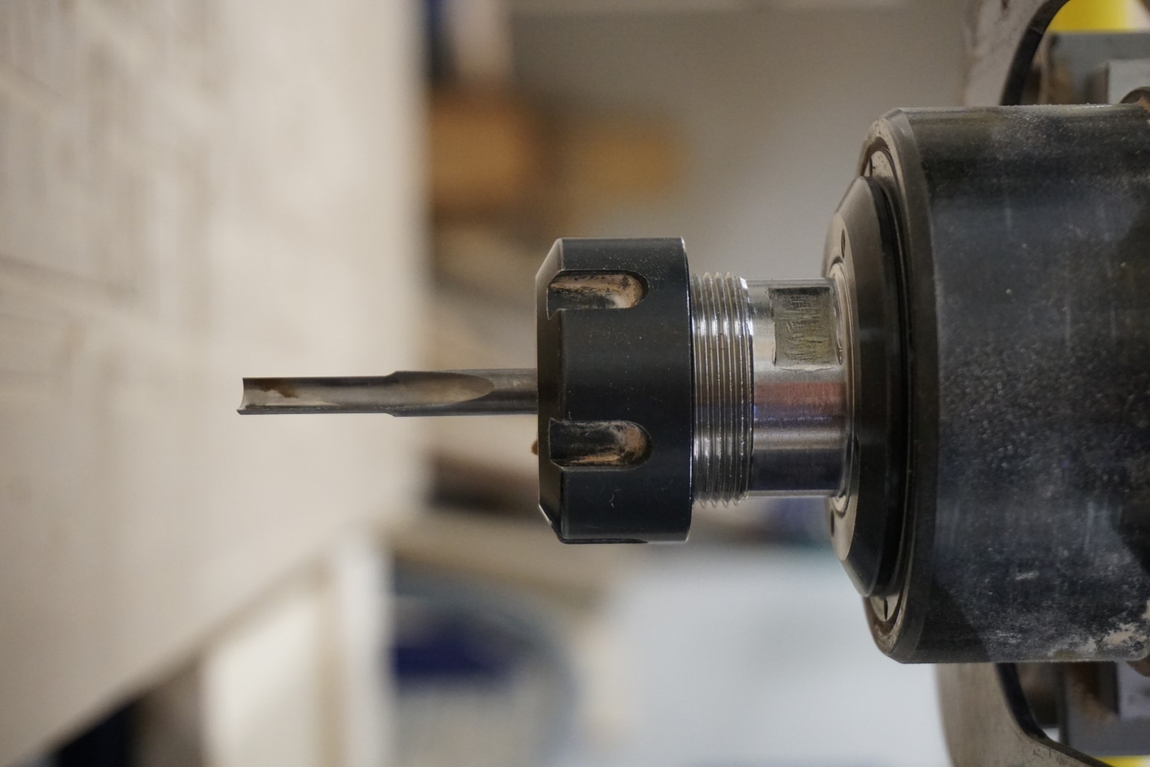
Next up is to set up the tools and toolpaths. I’ll be using a 1/4” flat end bit and stay with the defaults provide.
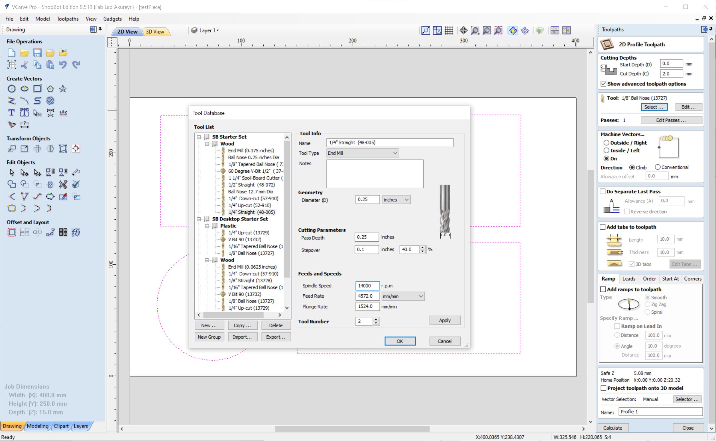
Here I have set the cut depth and selected the tool.
Machine vectors!
I want to emphasize this part! Selecting how the tool follows the path is important! For this design, I want the tool to go on the OUTSIDE of the path, so the specifications of the parts are not violated. The entire width of the tool will be outside of the path!
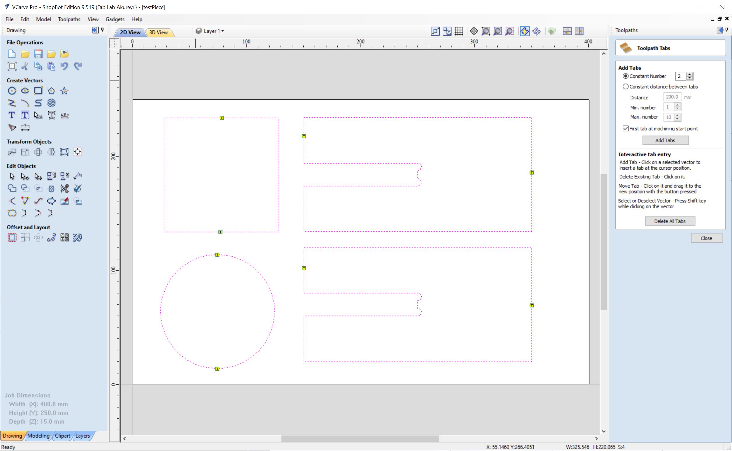
Tabs
I then select the tabs option, that makes sure the items are not fully cut out and will not go flying around the room when milled.
Adding tabs is important! Here I use two per path and select the positions manually. You can have the software place them automatically, specifying the spacing. This can be good, but sometimes the tabs end up in difficult to reach places, making removal and sanding of tabs difficult.
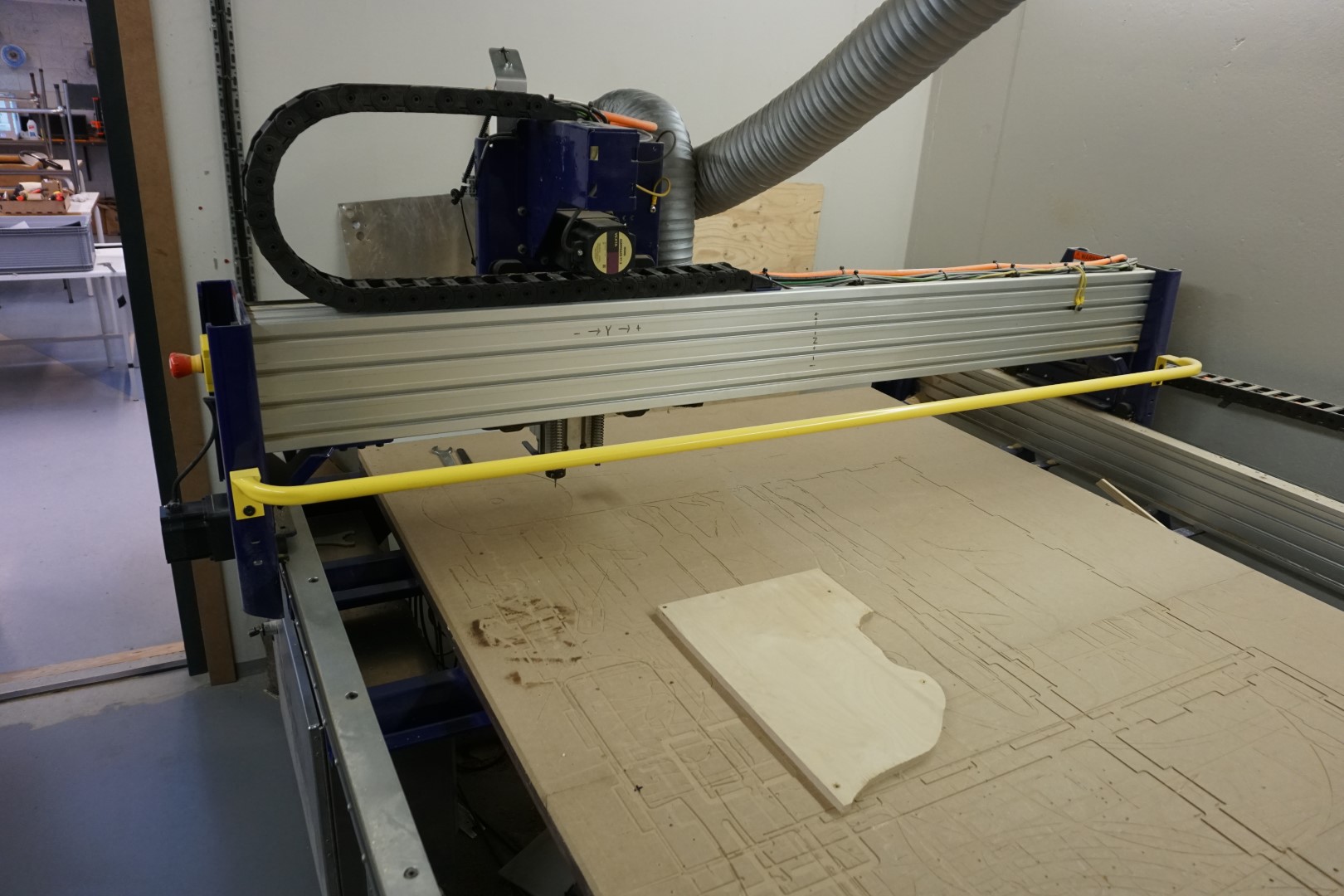
Mounting the piece
We use a scrap board fixings, that means we drill and screw the pieces into the board to hold them. When working with oddly shaped objects, creativity might be needed to hold the pieces in place!
Setting up the machine
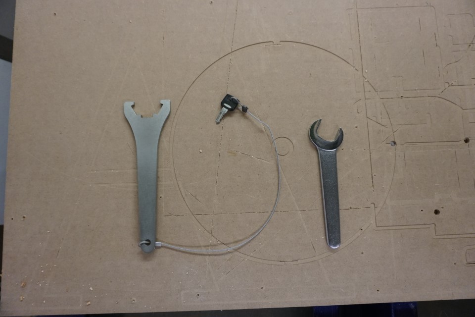
Keeping the bit removal tool attached to the key needed to activate the spindle is a simple trick to make sure the spindle is never active when a tool change is performed.
Next to the Shopbot there is a Windows PC, which controls the machine. It is not connected to the internet and is configured to not shutdown unless explicitly told to. Files are transferred via USB sticks and it’s recommended to copy the files from the USB to a working directory on the computer.
When setting the Z (height) axis, you use a piece of metal connected to the machine to which the mill bit is lowered on. Once they touch, the control software will detect connectivity. It is a smart move to touch the mill bit with the metal plate before performing the calibration, to make sure that the connectivity is there. If it’s not, it could damage the work piece and machine if the mill bit is lowered too far.
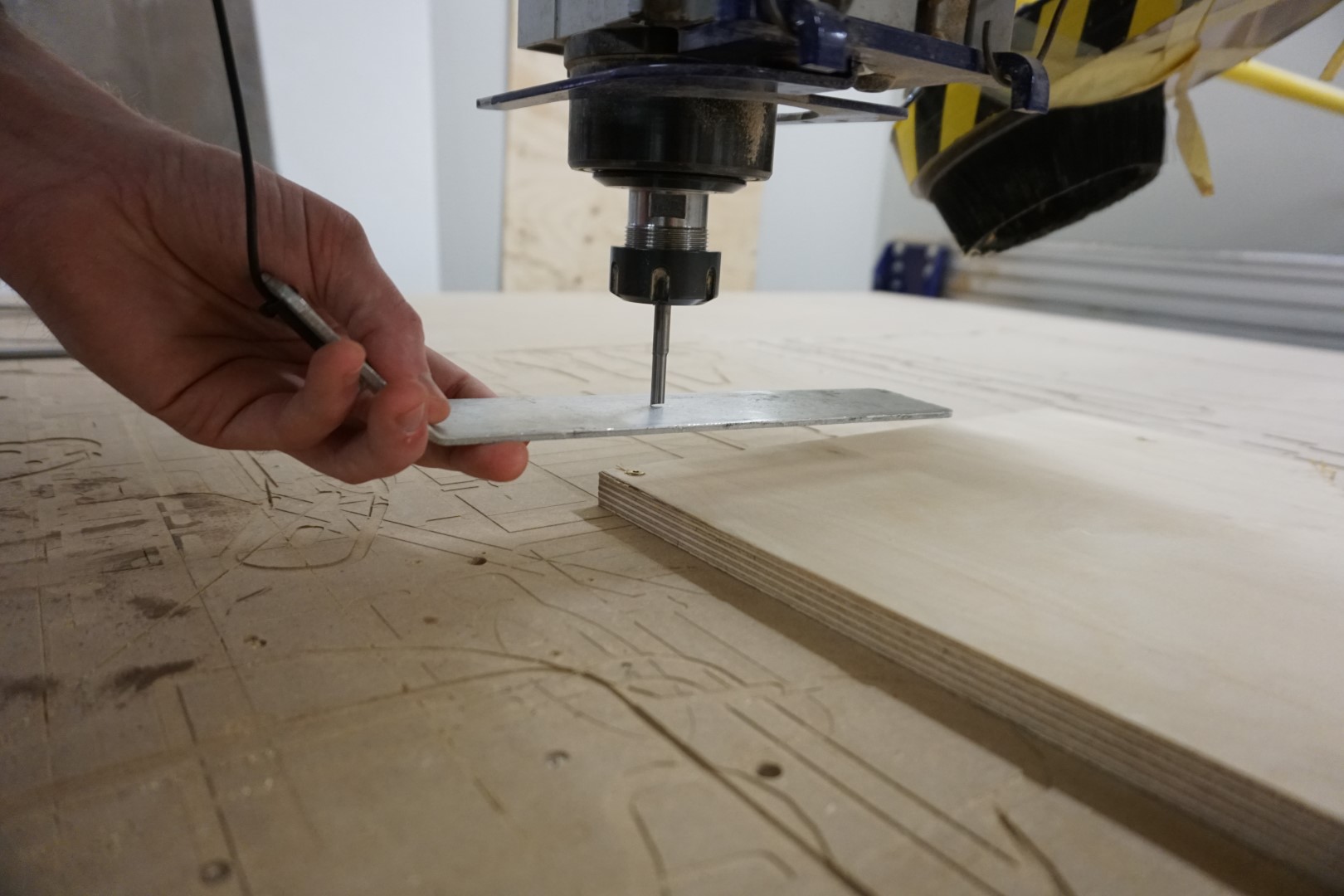
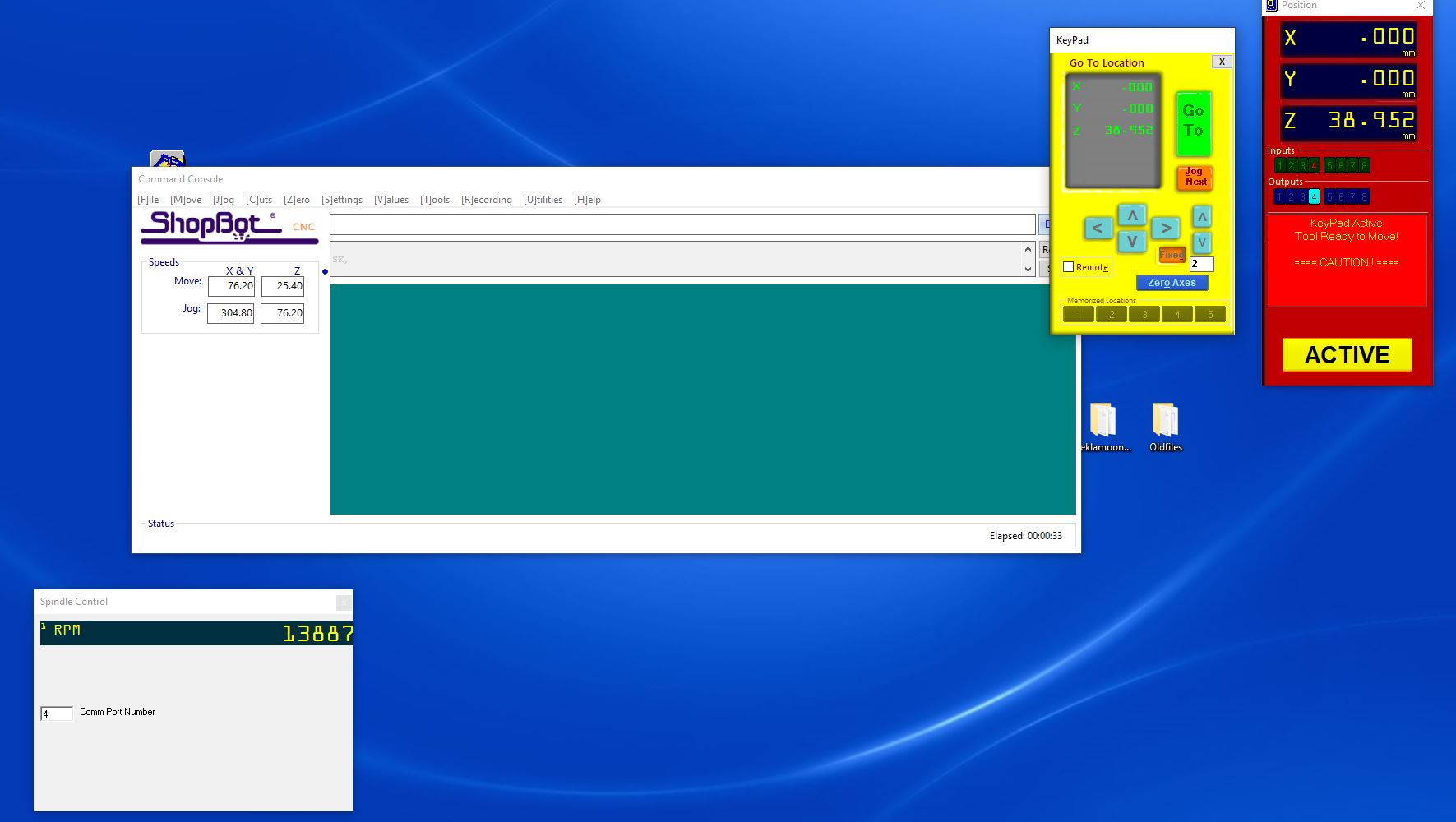
When working correctly, a input field in the software will light up.
After zeroing all three axis and loading the file, all is set!
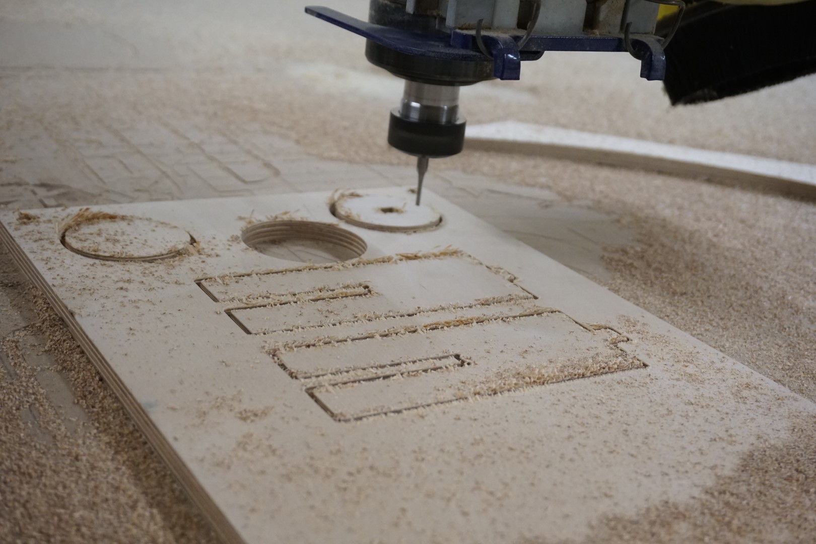
Running the job
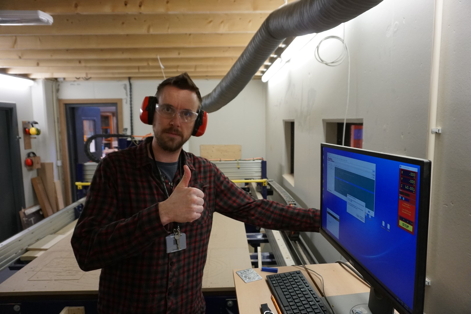
With goggles and ear protection, I start the milling process.
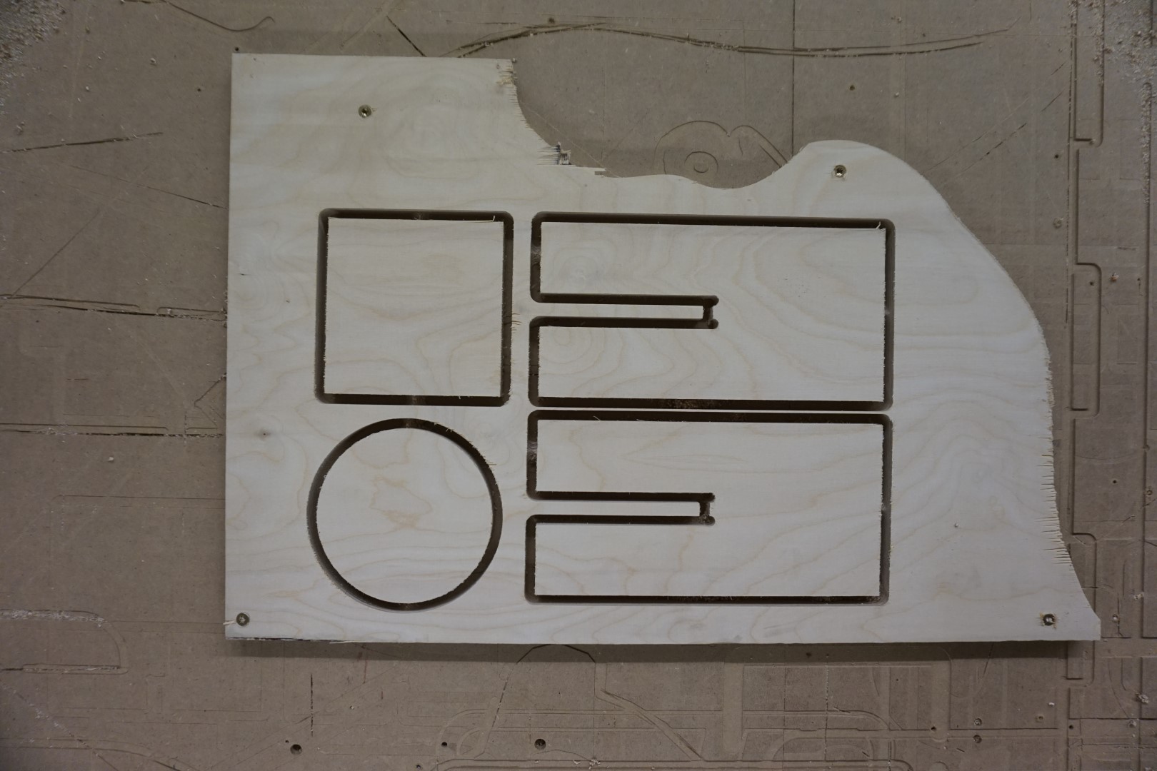
It did not take long and we were left with this!
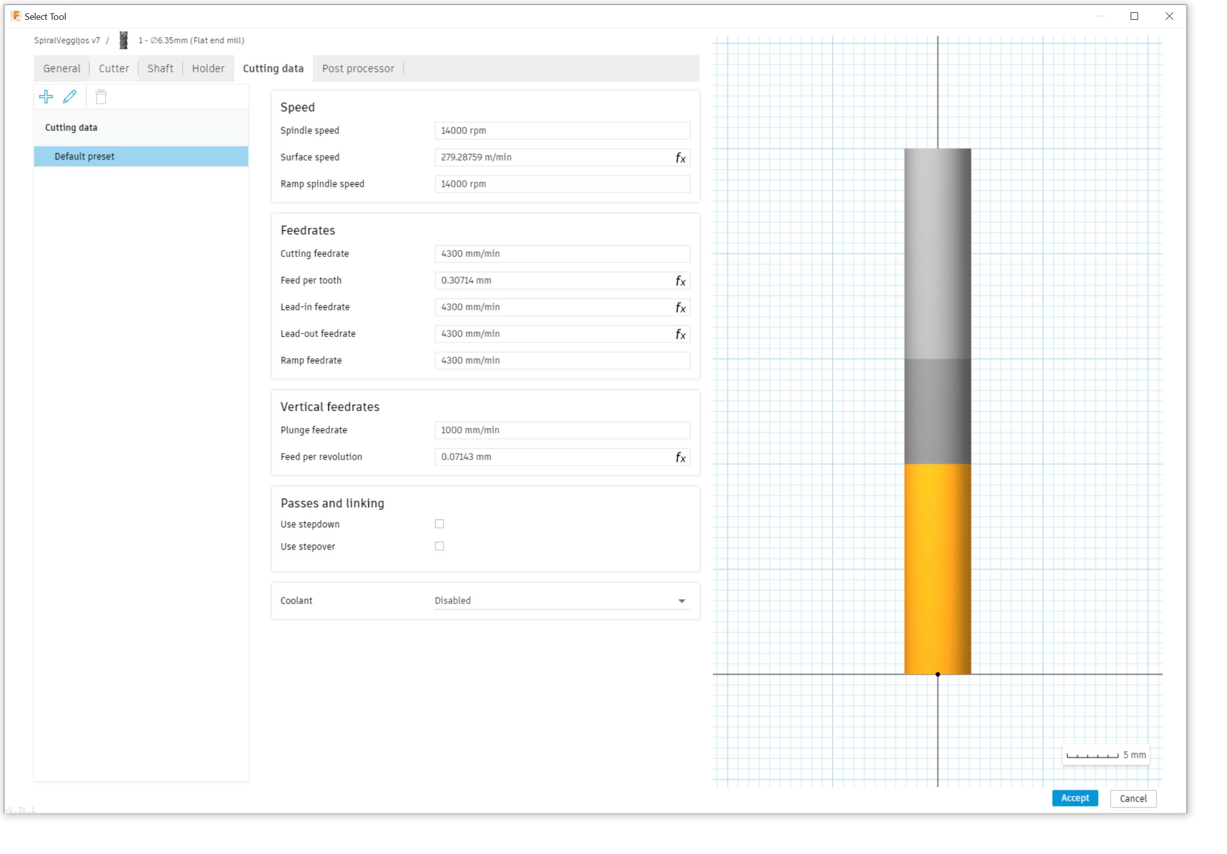
I gathered a bit of the chips for inspection. They seem fine to me, not to small and not to big. If they were to small, like powder, that would indicate that the RPM of the spindle is too high or the feed rate (moving speed) is too low, or a combination of both. Remember, I used the default settings for the machine for this piece which was:
| RPM | Feed rate |
|---|---|
| 14.000 | 4600 mm/min |
Test results
The job was twofold. Firstly it was a test to see if the specifications of the job hold, testing that on both a circle and a rectangle. Secondly, it was a dogbone test, just to try them out!
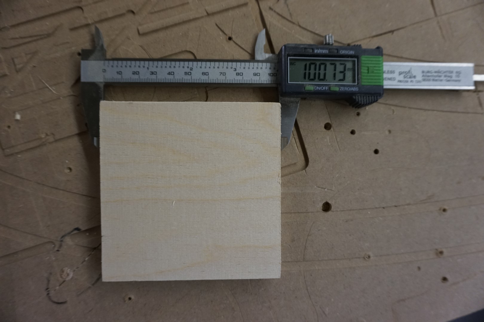
Circle & square
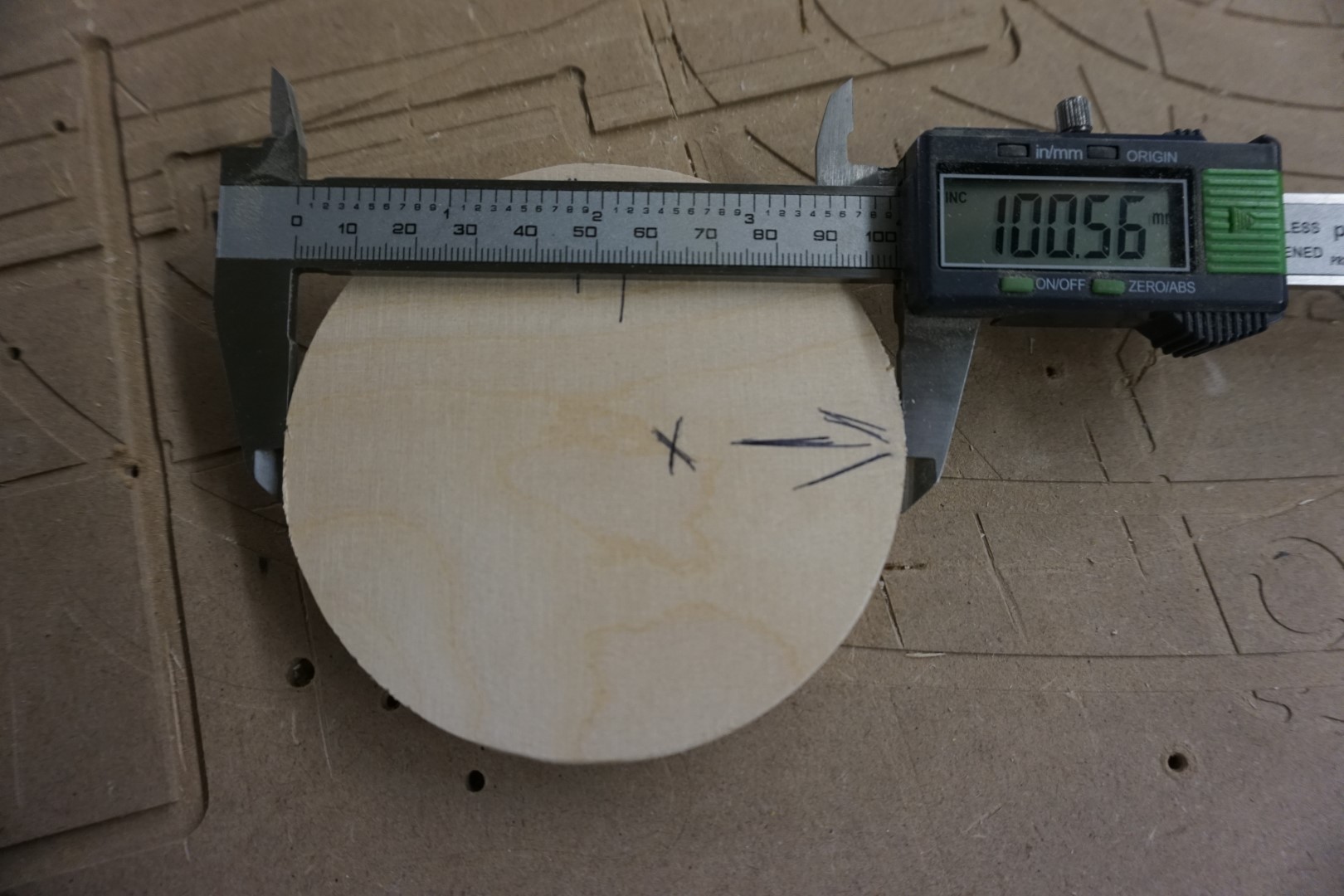
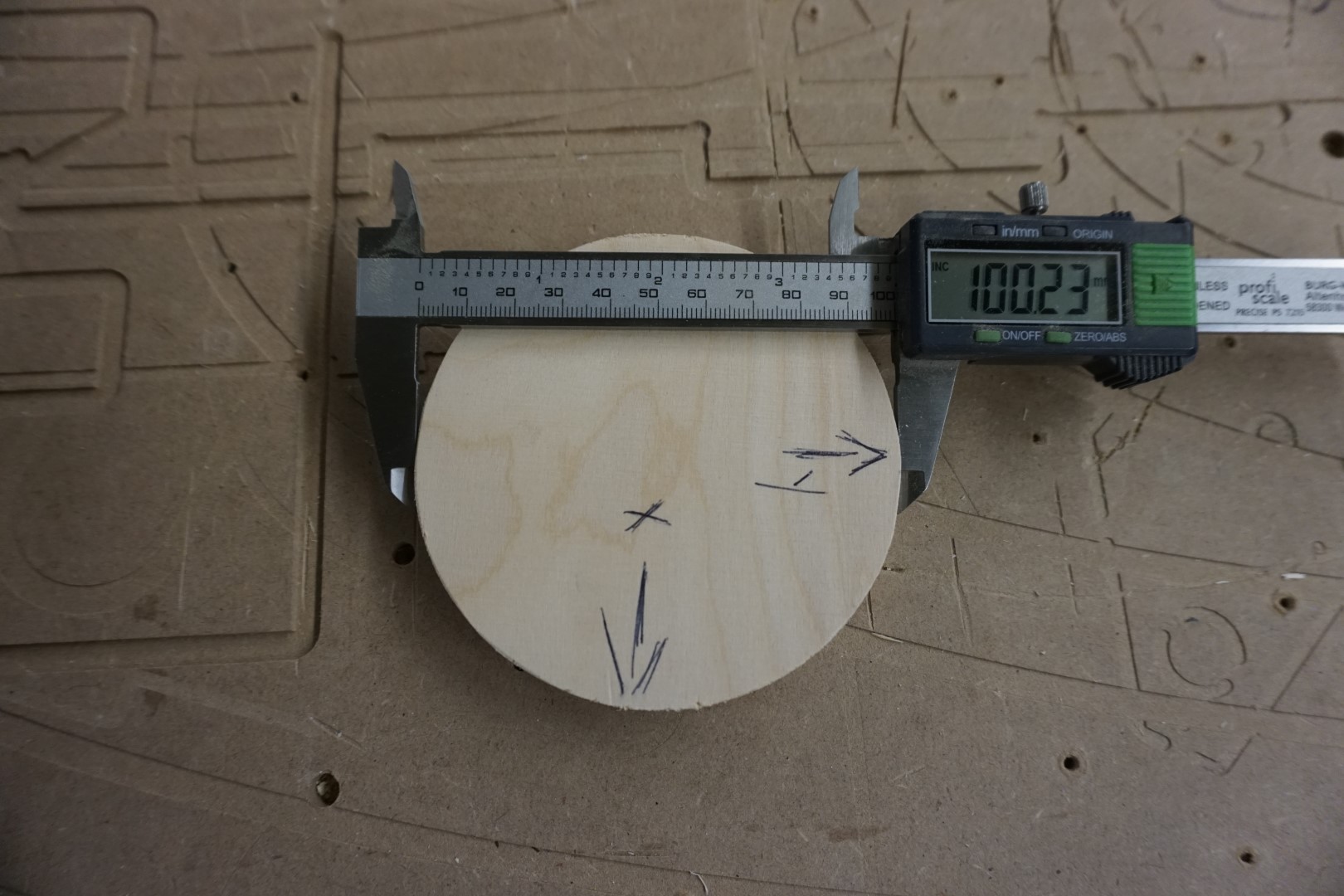
X axis measured ~0.5mm to wide and Y axis measured about ~0.2mm to high.
The square was approximately the same. (Missed a photo of the Y axis)
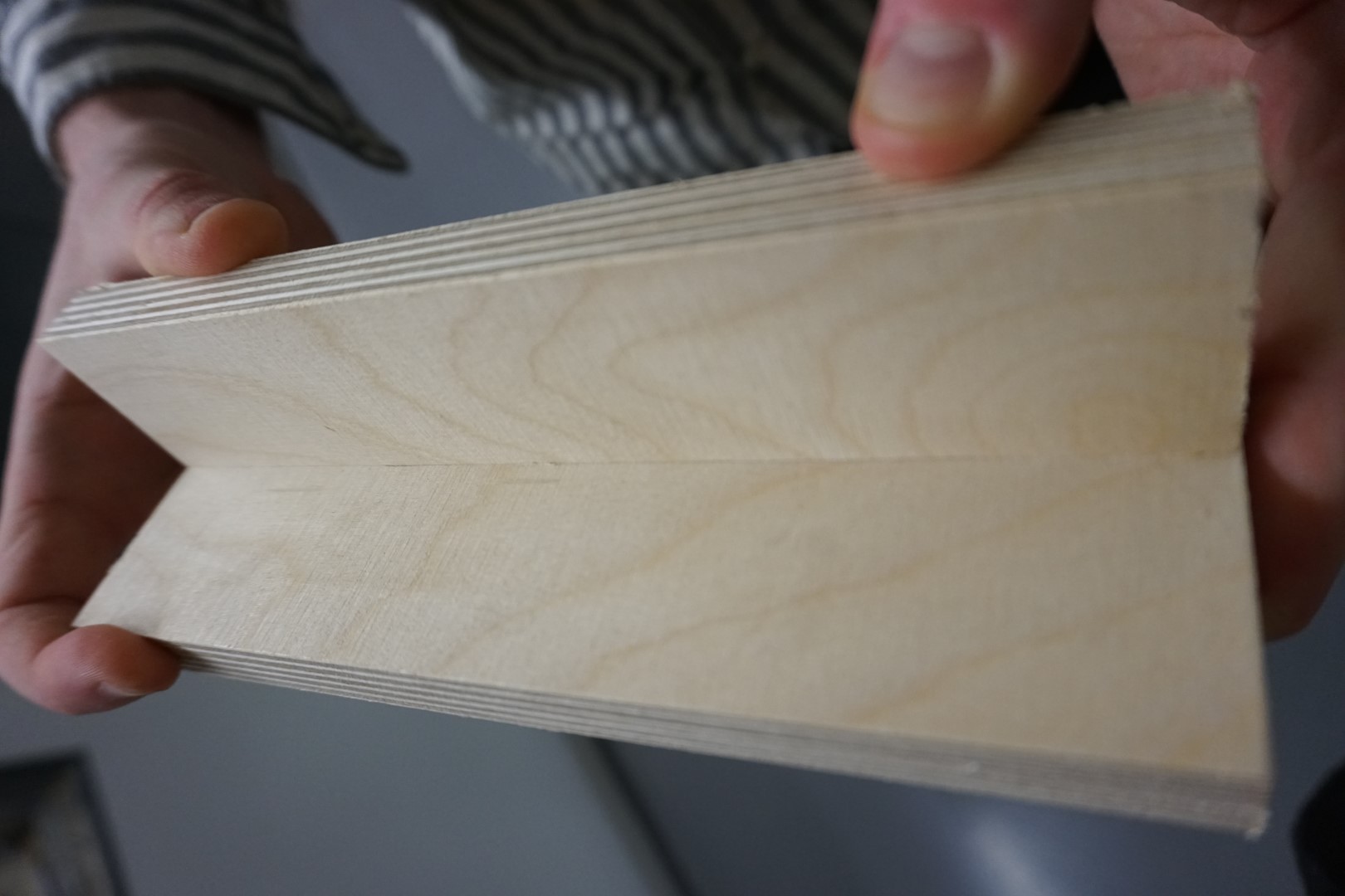
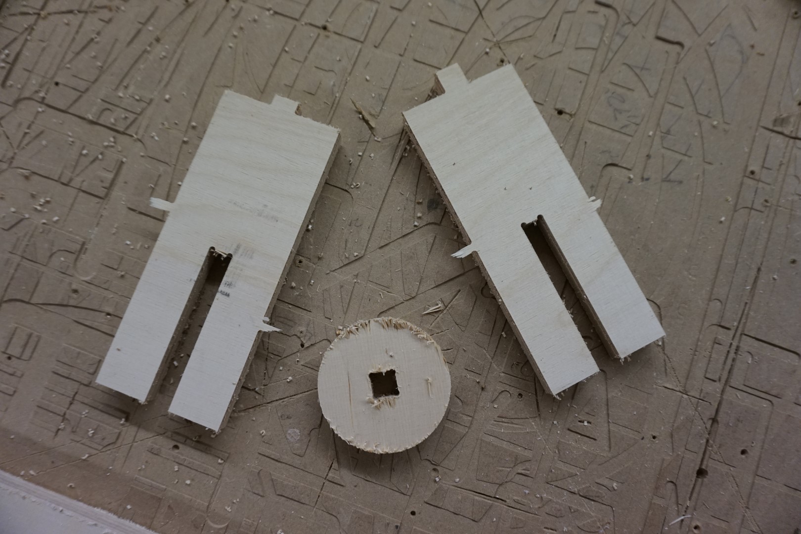
Dogbone & fail!
Next up, the dogbone. I find the once where the cutout circle show a bit ugly so I made sure to have both of the “ears” on the downward, if so to say. That makes them hidden once the pieces are assembled.
But I guess I was occupied with that thought then with what material I was working with! Turned out I entered the wrong width when making the pieces so way off!
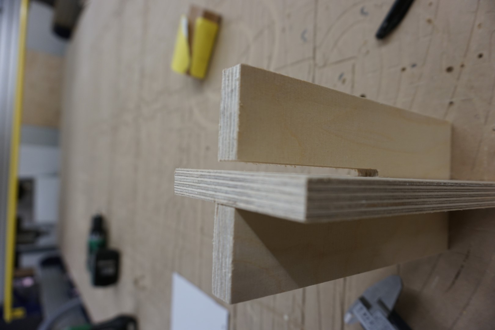
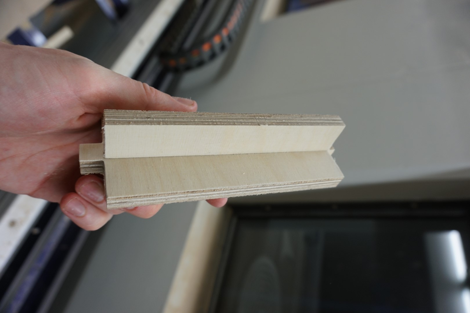
But, on the bright side, this was just a (valuable) test. I was able to see that the joint is actually quite nice when assembled!
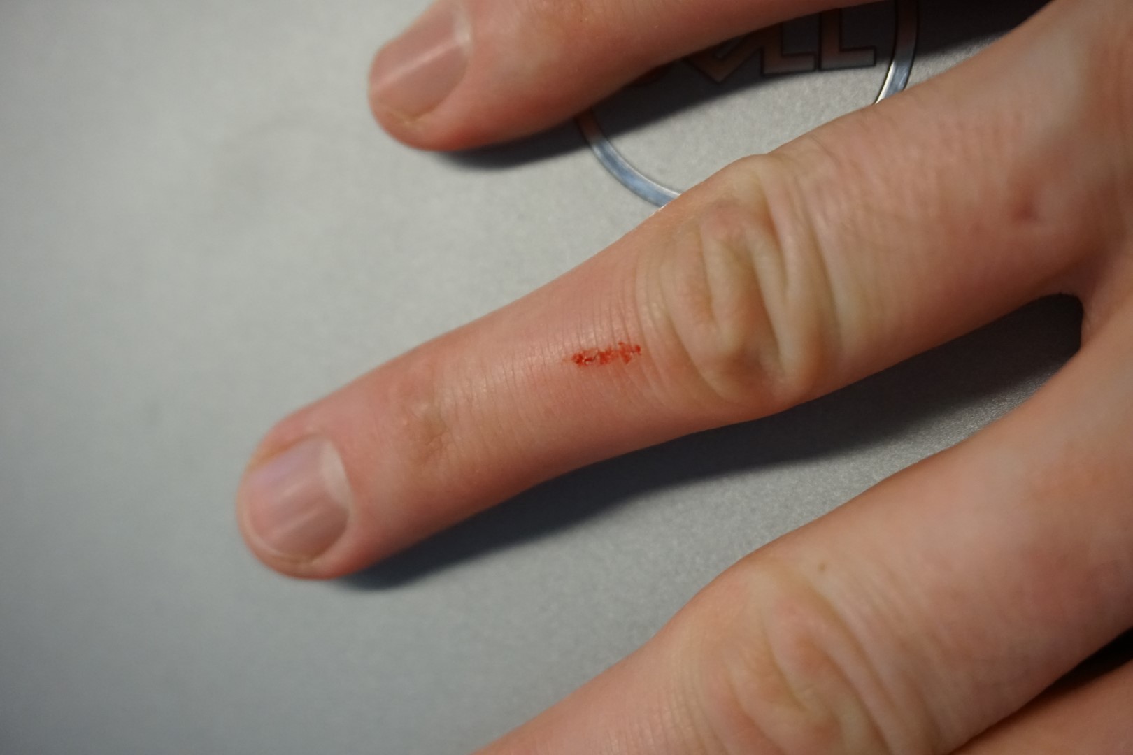
No animals were harmed in the making of this documentation (only me)!
I suffered a horrible cut during the milling process!
Don’t worry, I’ll survive.
Project Spiral light
Inspiration
A short while ago my wife mentioned that she had an idea for a project that I might be able to do in the Fab Lab. The idea was a wall mounted light contraption consisting of a light source in the middle, close to the wall, and different sized rings of light around it.
I figured that this would be easily done with the Shopbot.
Then my son got a new toy, a marble tower that can be assembled in different ways. One of the items in it, is a spiral funnel that the marbles travel down before falling through the hole in the middle.
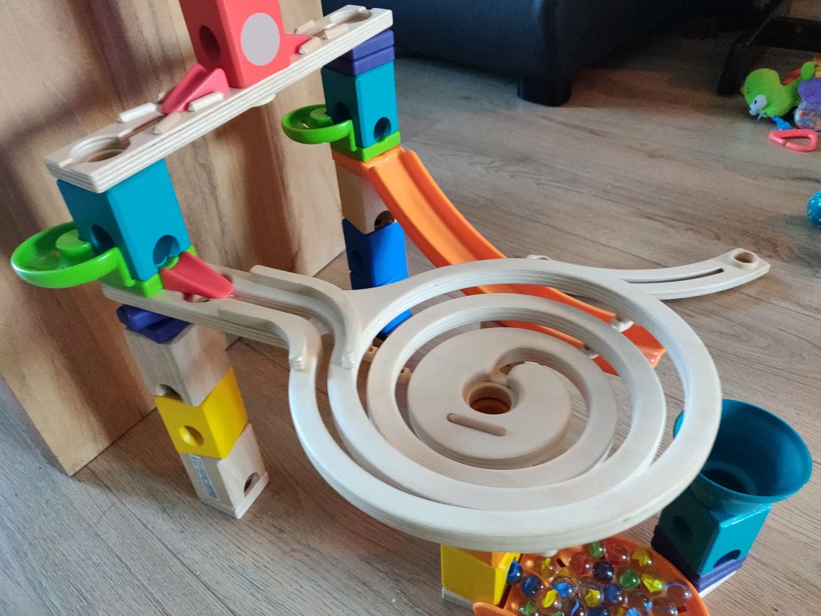
Upon inspection, I noticed that the funnel was made out of plywood. Very interesting! I want to make a similar design, machining a spiral into the material and then adding some sort of fixture(s) to enforce depth. I find this a very interesting way to implement a curved surface or depth while using a single piece and not using a lot of material.
I need to figure out some way of propping the spiral out of the plywood. At this moment of writing, I have not decided on the final way, but I have a few ideas which. The source of light is also not final (and out of scope for this week really).
- Fixing a rod in the middle that pushes the spiral out.
- Like in the toy spiral, drilling holes in the sides and making these sorts of knees pushes the next level out.
- Similar to the knees, but without drilling: Manufacturing a wedge or a “step” that goes between the spirals, pushing them out.
The light source will either be a bulb in a fixture or a led strip on back of the spiral. I’m leaning towards the latter.
Design work
Sketching and extruding
For this project I want to do all the steps within Fusion 360. Going from the first 2D sketch to a 3D model with textures and from there to generating the toolpaths, all within the same program is quite nice!
I looked at what stock we had laying around and found a piece of nice plywood that I could use. The useable area of that piece is about 800*800 mm.
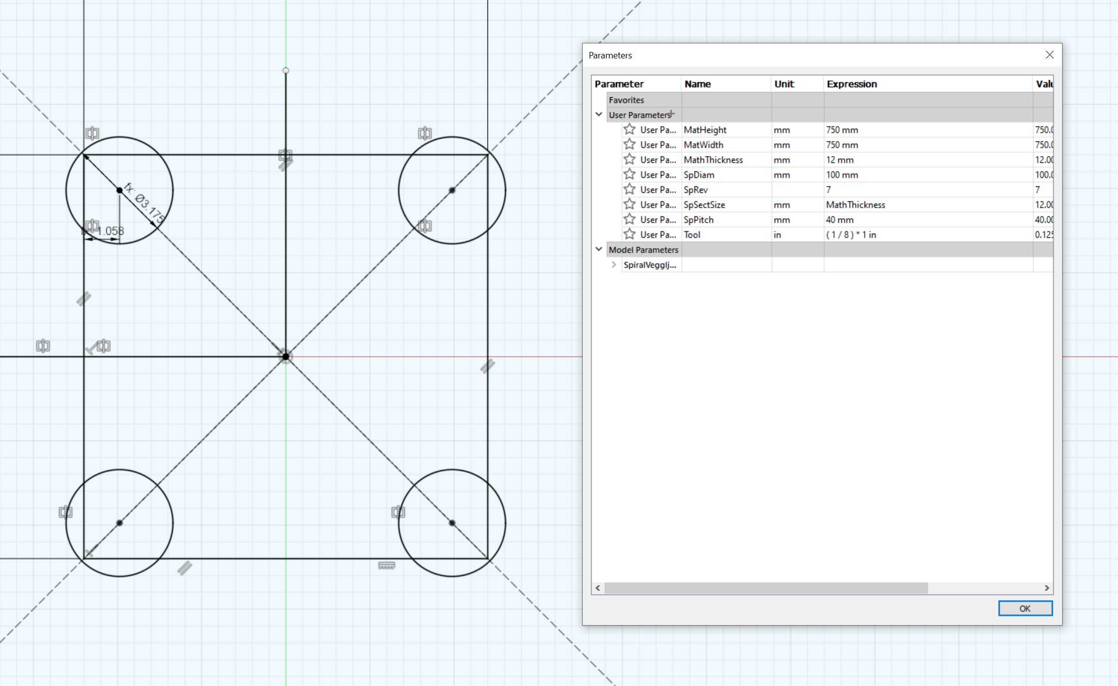
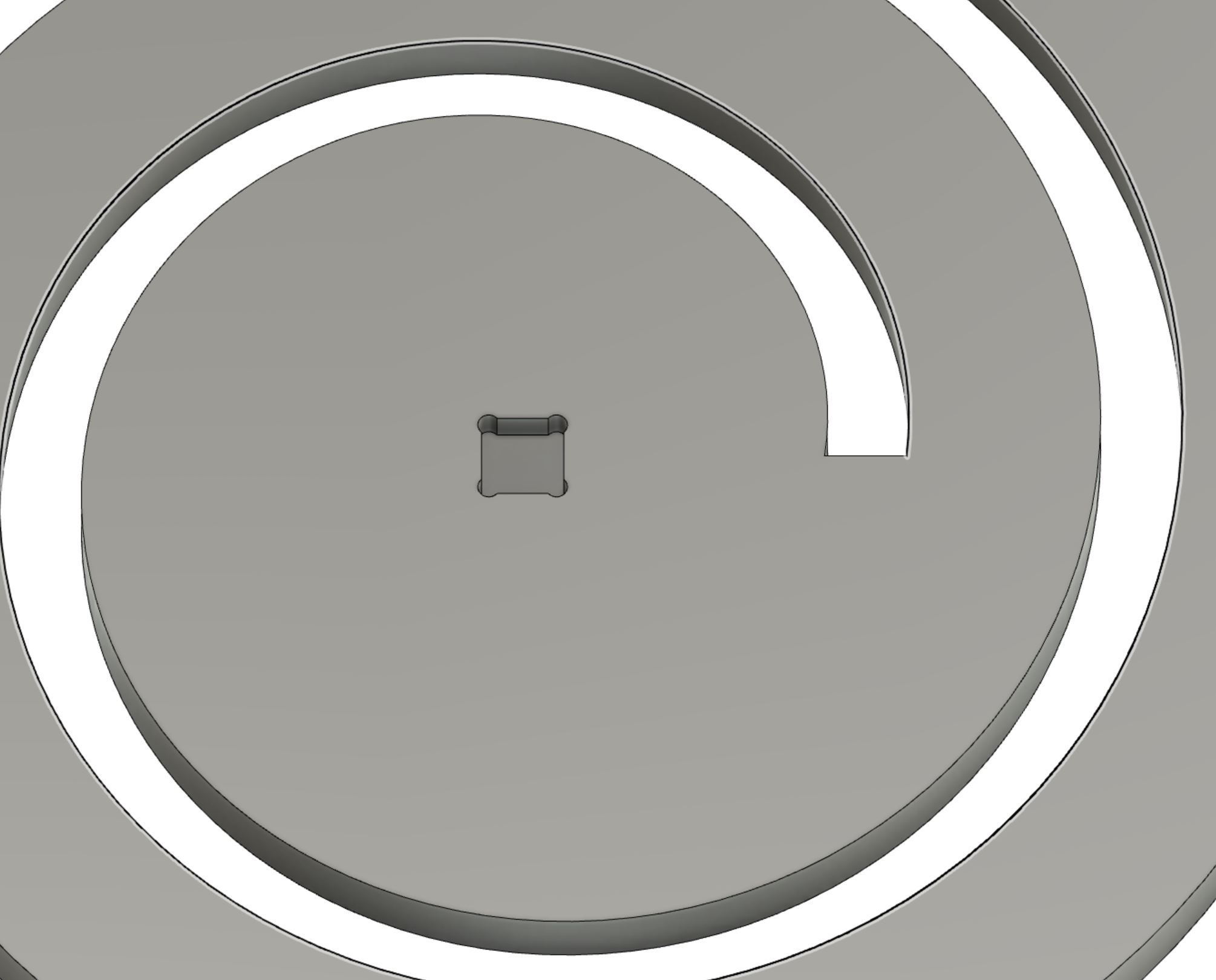
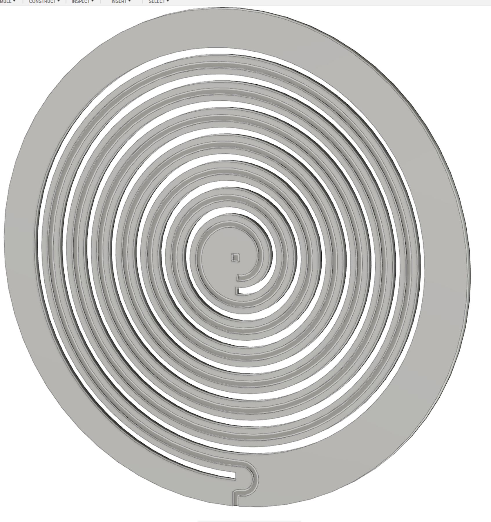
Building on what I learned during the CAD week, I knew I wanted to have this design parametric. I entered the dimensions of the plywood into the Fusion 360 parameters section and then I started experimenting with the coil tool.
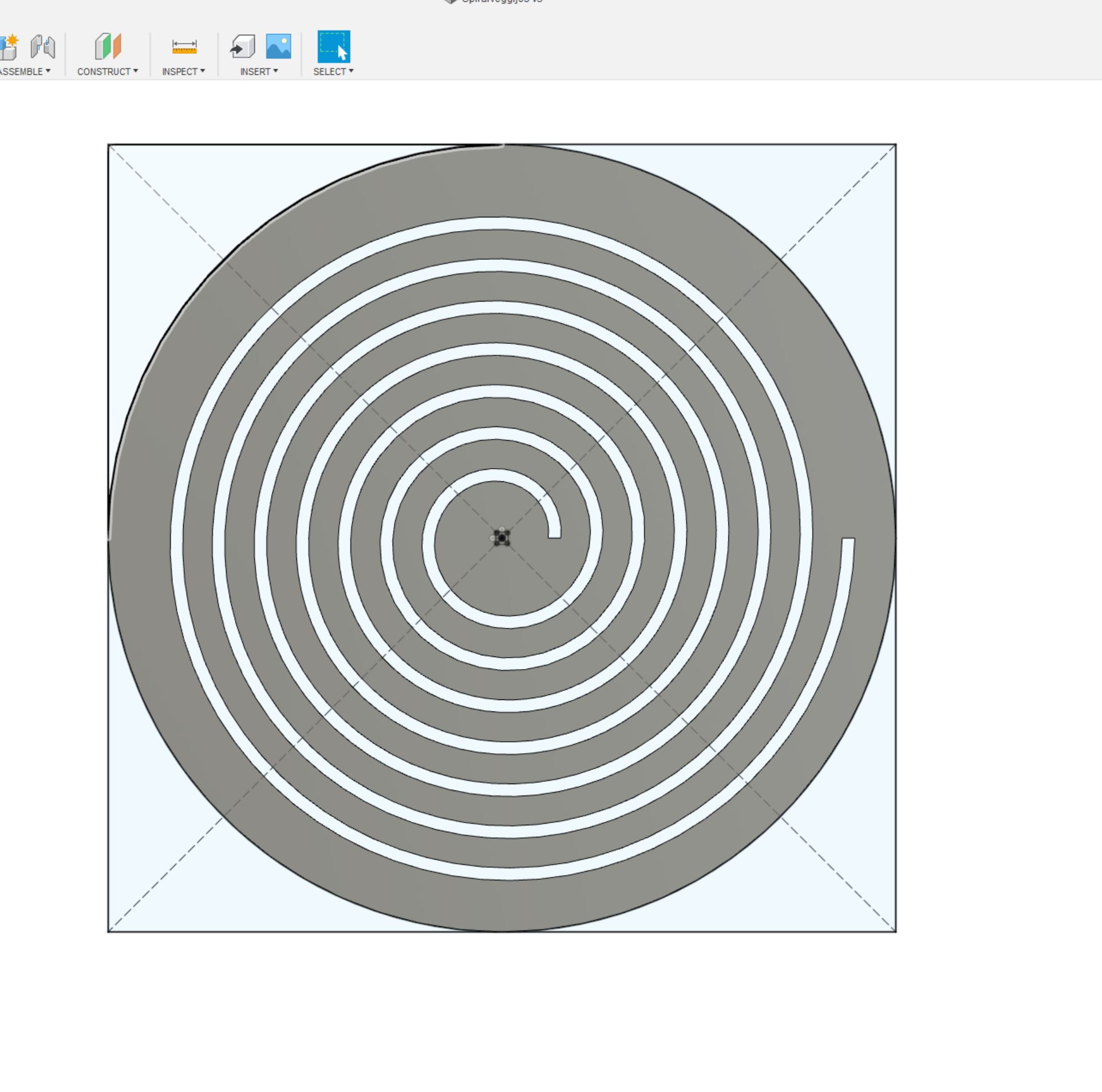
For the center, I added a square pocket with dogbone cutouts, to add a piece to prop out the center.
Included in the screenshot is the parameters dialog.
I experimented with the values before adding them to the parameters settings, just to get a feel for the tool and the design. Then later on I could quickly fine tune the values.
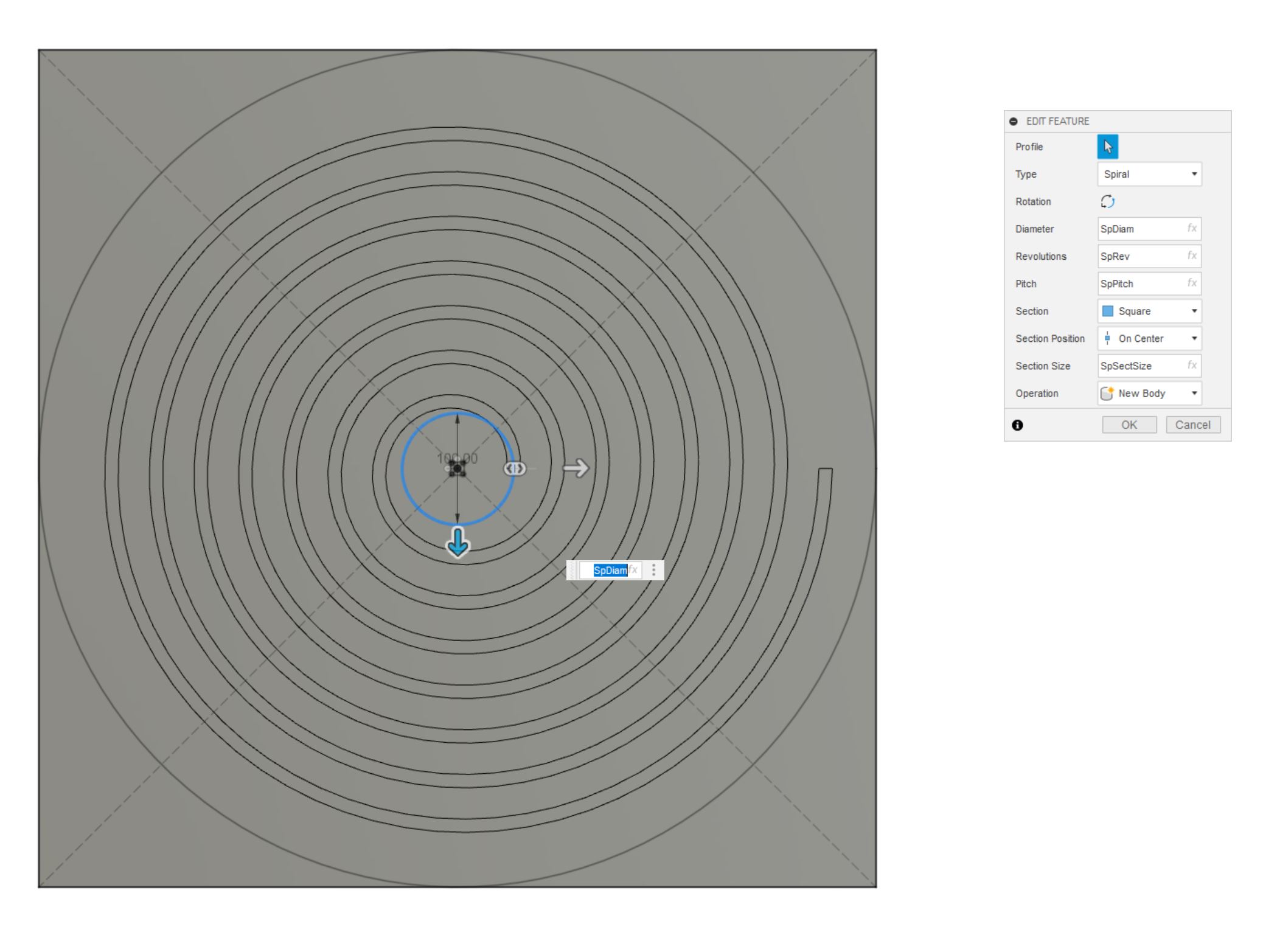
I then added an offset from one edge of the spiral, to mill a path for the wiring.
Manifacturing
Once I was happy with the piece, I selected the Manifacturing section in Fusion. I set up the work area, making sure to set the orientation of the axes correctly.
For most of the cutting, I used the 1/4” flat end bit. For the center dogbone, I used the 1/8” flat end bit.
First problem
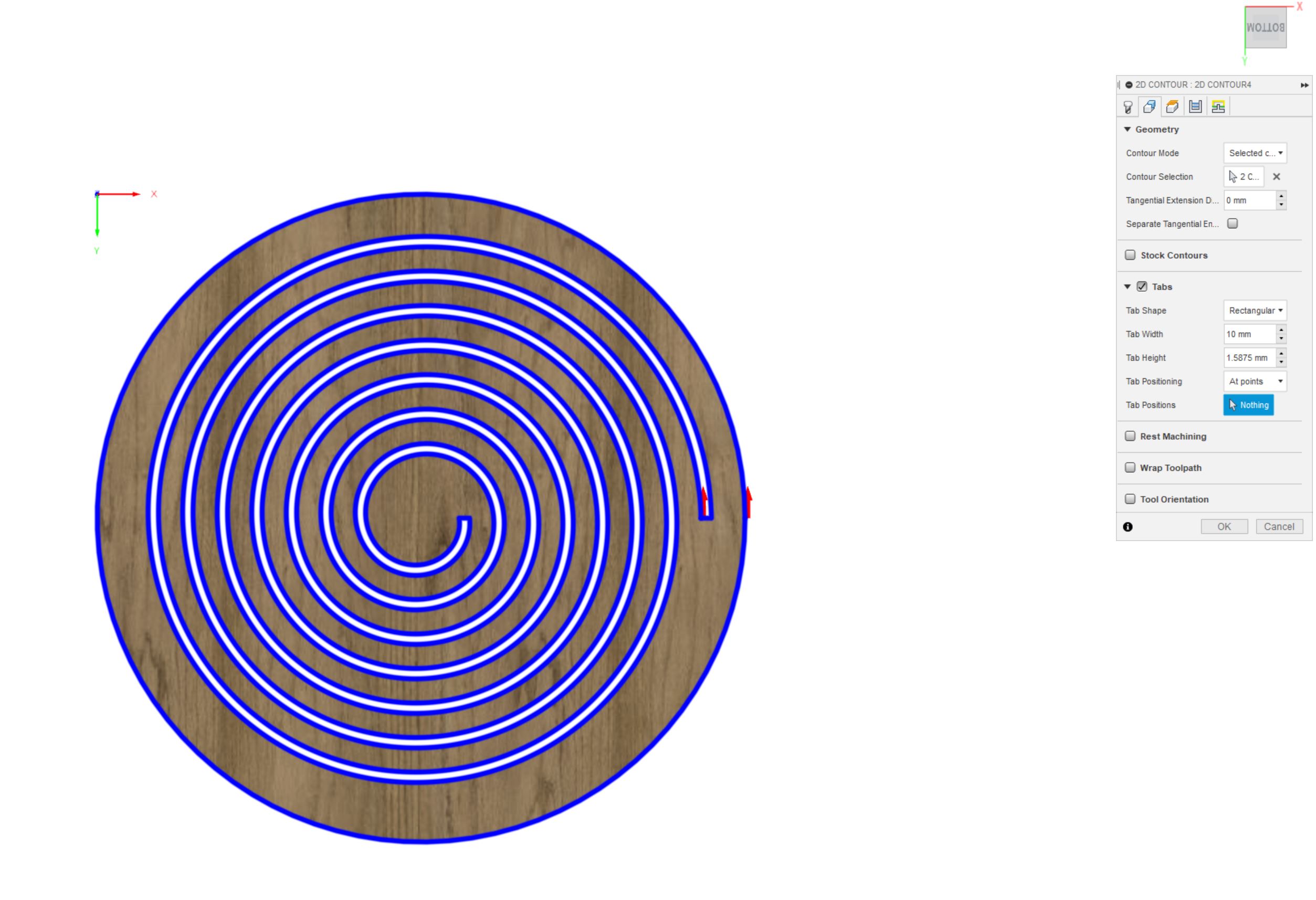
When the time came to add tabs to projects, I ran into a problem. Fusion did not let me add tabs to the spiral part of the design, only the outer circle. I do not know to source of this problem, but I did decide to just try it out.
I did not have the feel for how stiff or soft the spiral part would be, but this is meant as an exercise!
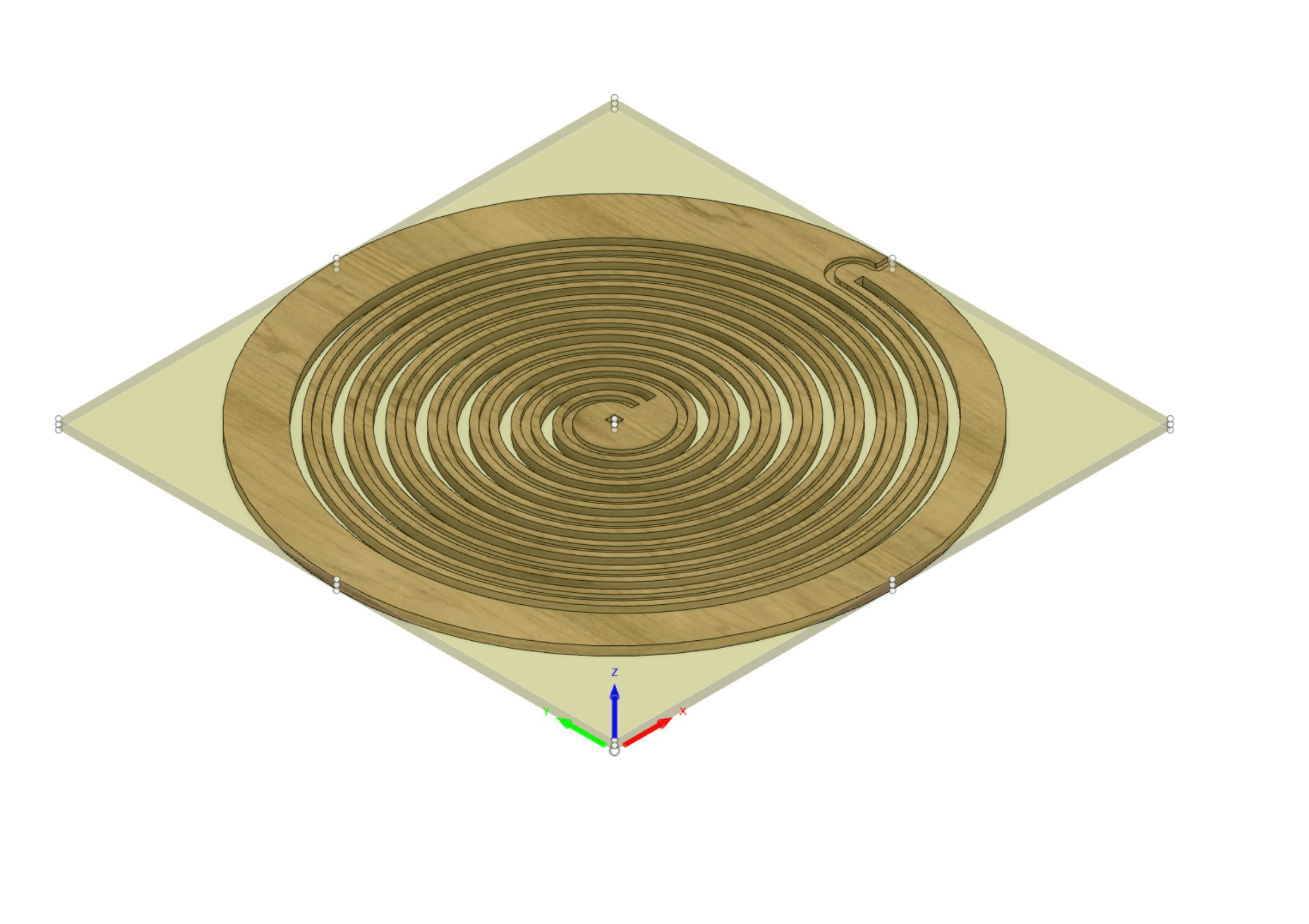
Render
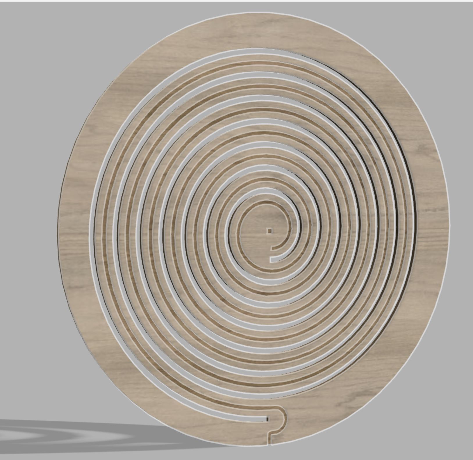
Just for fun, I rendered the spiral part of the design.
Mini prototype
Because I really had no idea of how flexible the spiral would be, I decided to make a mini prototype. Using fusion, I exported the design as a .dxf file to open in Inkscape. From there I adjusted fill & stroke to cut the mini-version with scrap MDF.
This resulted in a fun form, both the intended piece and the to-be-discarded one.
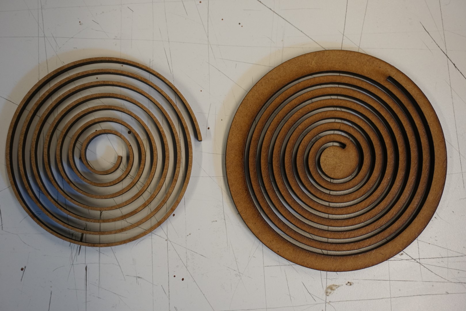
As it turned out, this was very flexible. This gave me a feel of how it might translate to the final piece. This was a fun little experiment in prototyping.
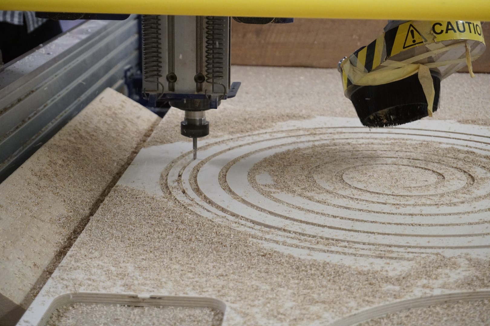
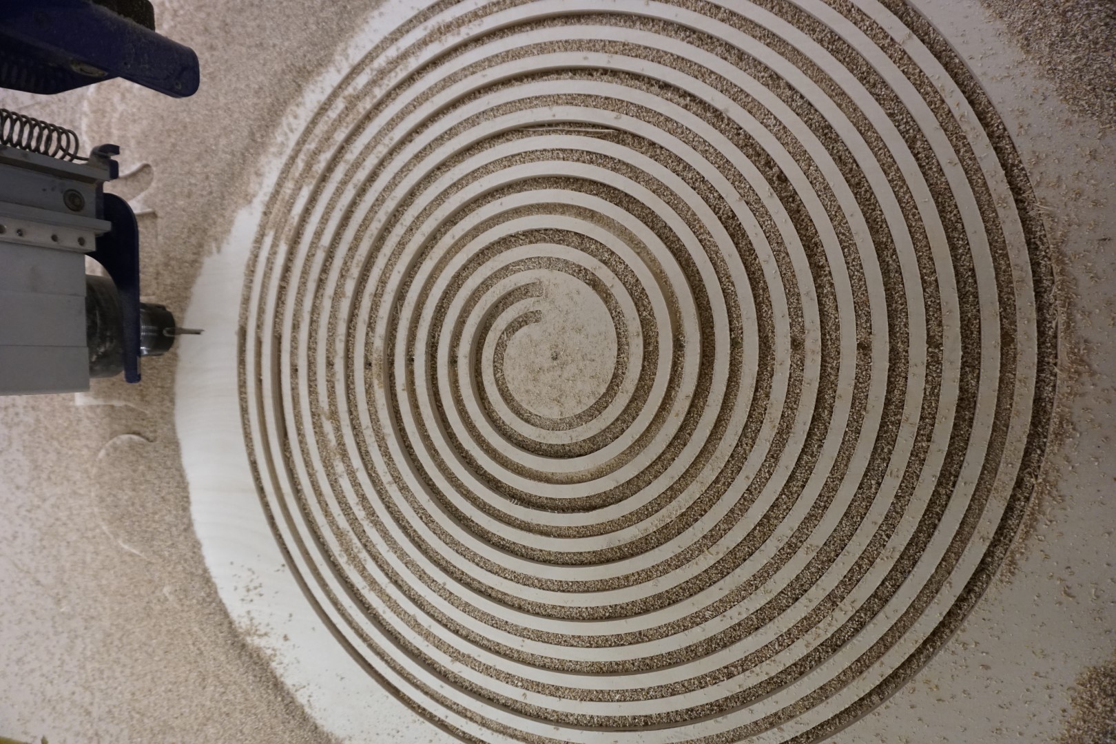
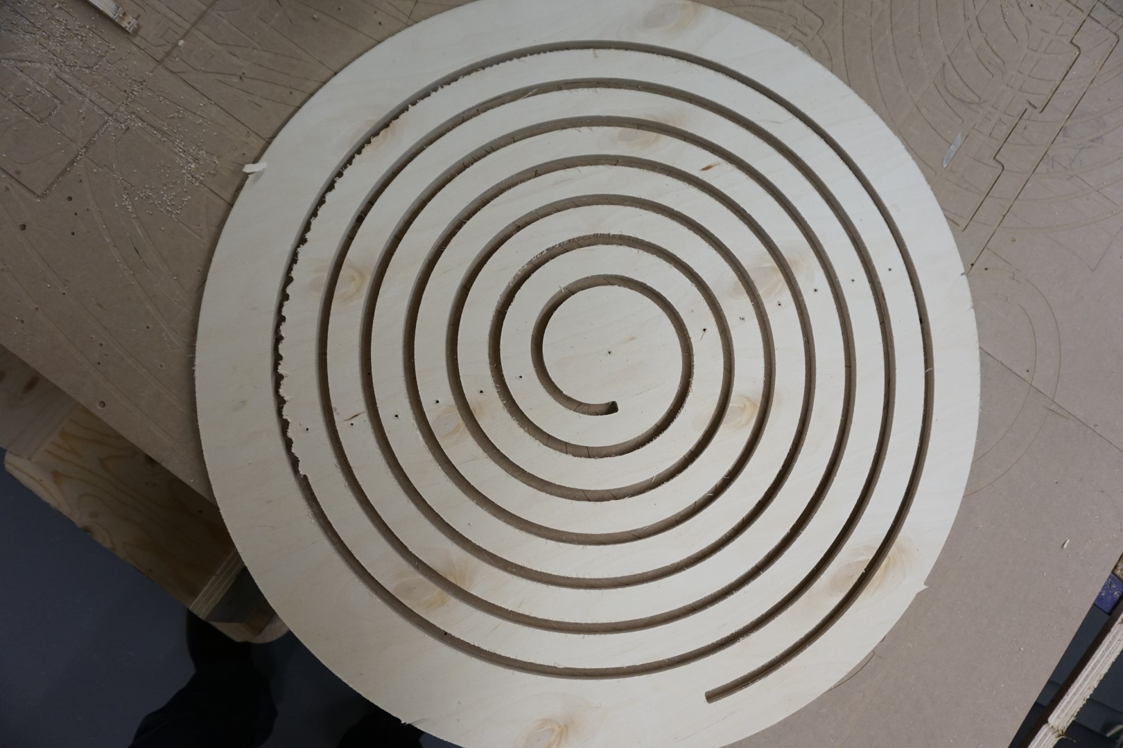
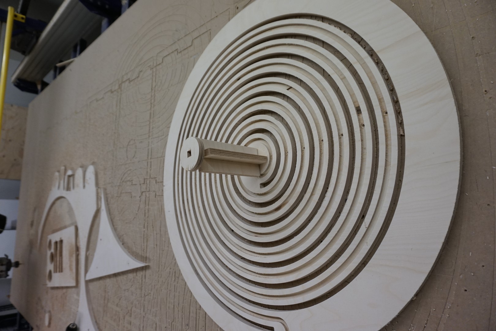
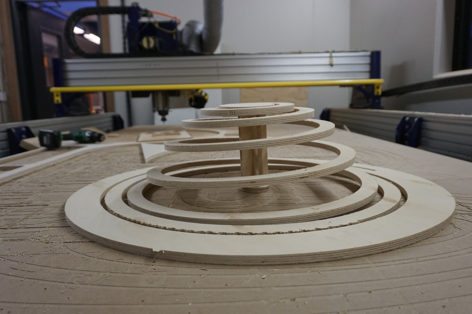
Milling the spiral
After mounting the previously mentioned scrap piece, with a usable area of approximately 800*800 mm, I started milling the spiral.
Using the 1/4” bit, I cut the spiral into a series of concentric circles. Now, this is where things got tricky. First of all, I probably should have milled the dogbone mount in the middle first, then milled the spiral for the wires, before actually cutting through the material for the final spiral.
We left the dust collector off to be better able to monitor the progress.
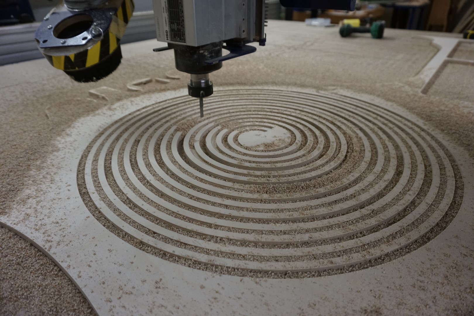
It turned out to quite flexible, so much so that it started vibrating heavily in the center when cutting through the material from there.
Heck with it, it’s a learning project! So I used a screw to secure the middle, to see if it would be enough to hold the spiral in place for the rest of the mill. This affects the final outcome, but hey, at least I’m learning!
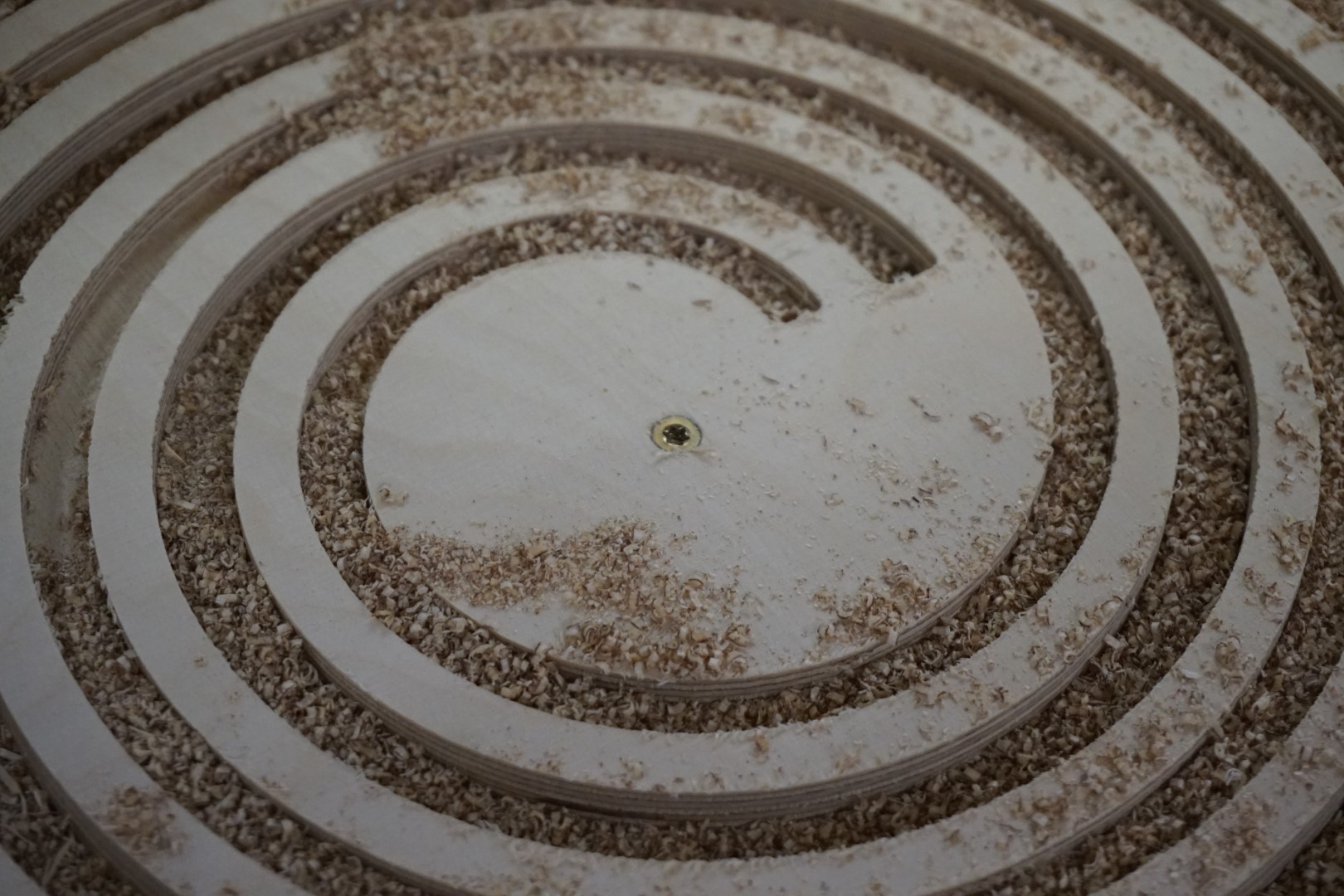
Continuing the milling, and almost running out of time with the (before kindergarten pickup), I quickly ran into the same problem. After just a bit of milling, the spiral started vibrating again. So I called it a day, continued with other duties.
The morning after
I brought backup to the office, put on both a belt and suspenders, downed a whole lot of coffee and went for it!
I used plenty of screws to secure the rest and continued milling. If this will end up on a wall one day, the holes can easily be covered by wood-filler.
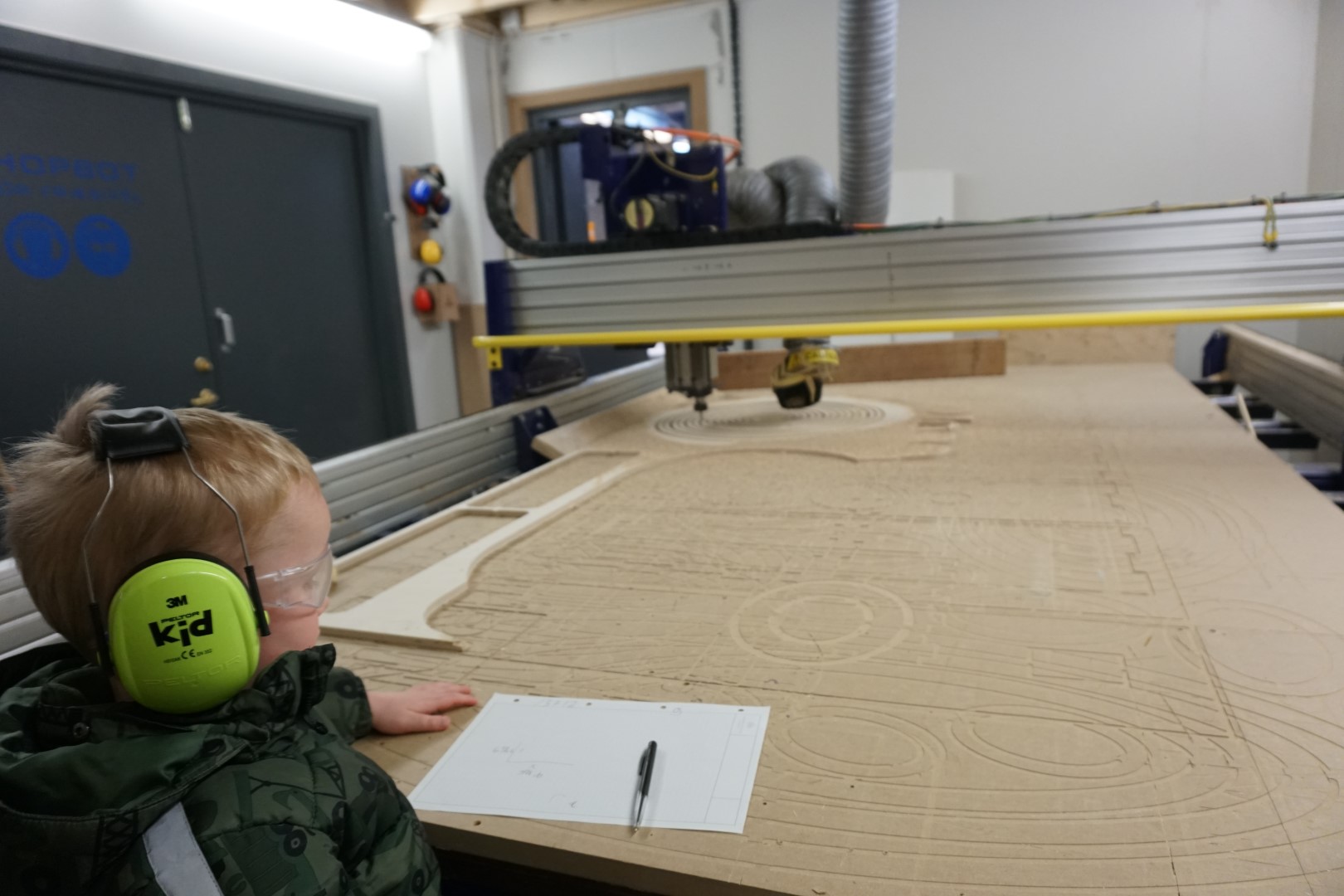
Heavily inspired with the helpful nature of the Paw Patrol, my scrupulous little helper managed to get me through the rest. He took plenty of notes for future projects.
Missing a photo of a small dogbone mount in the middle, that was cut last.
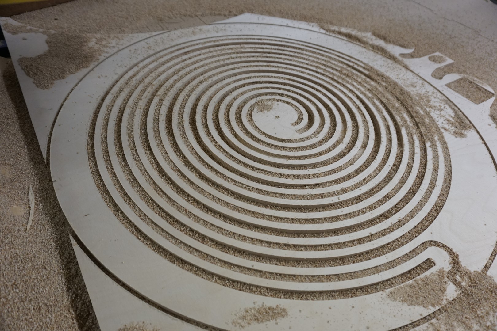
The result
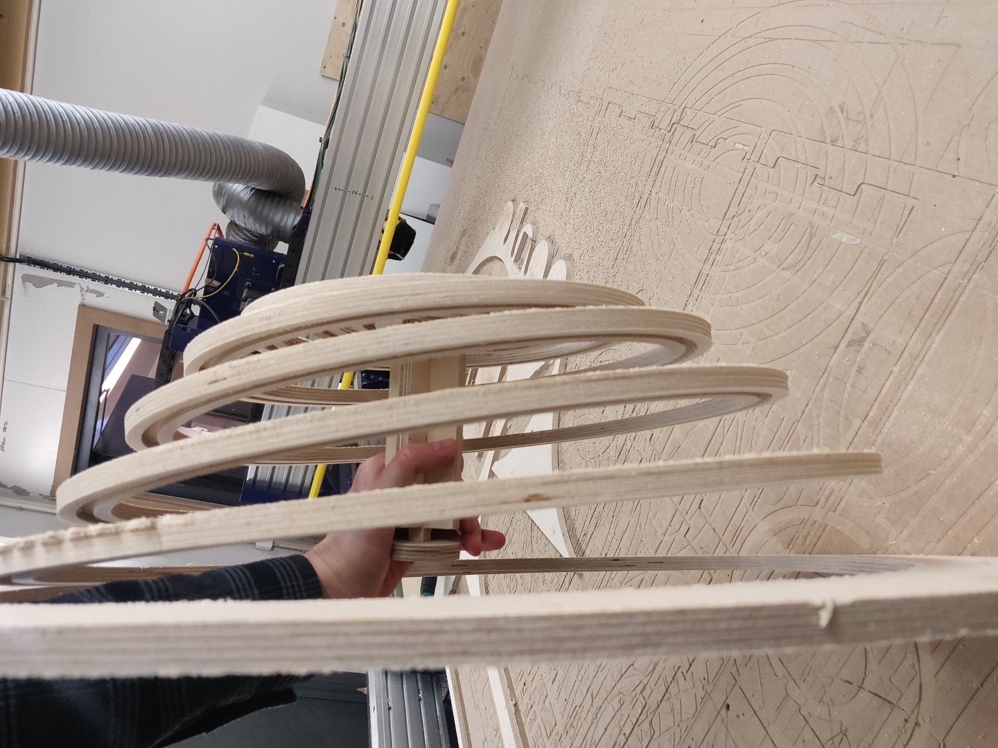
At this point, it was time to remove the screws and check out the result.
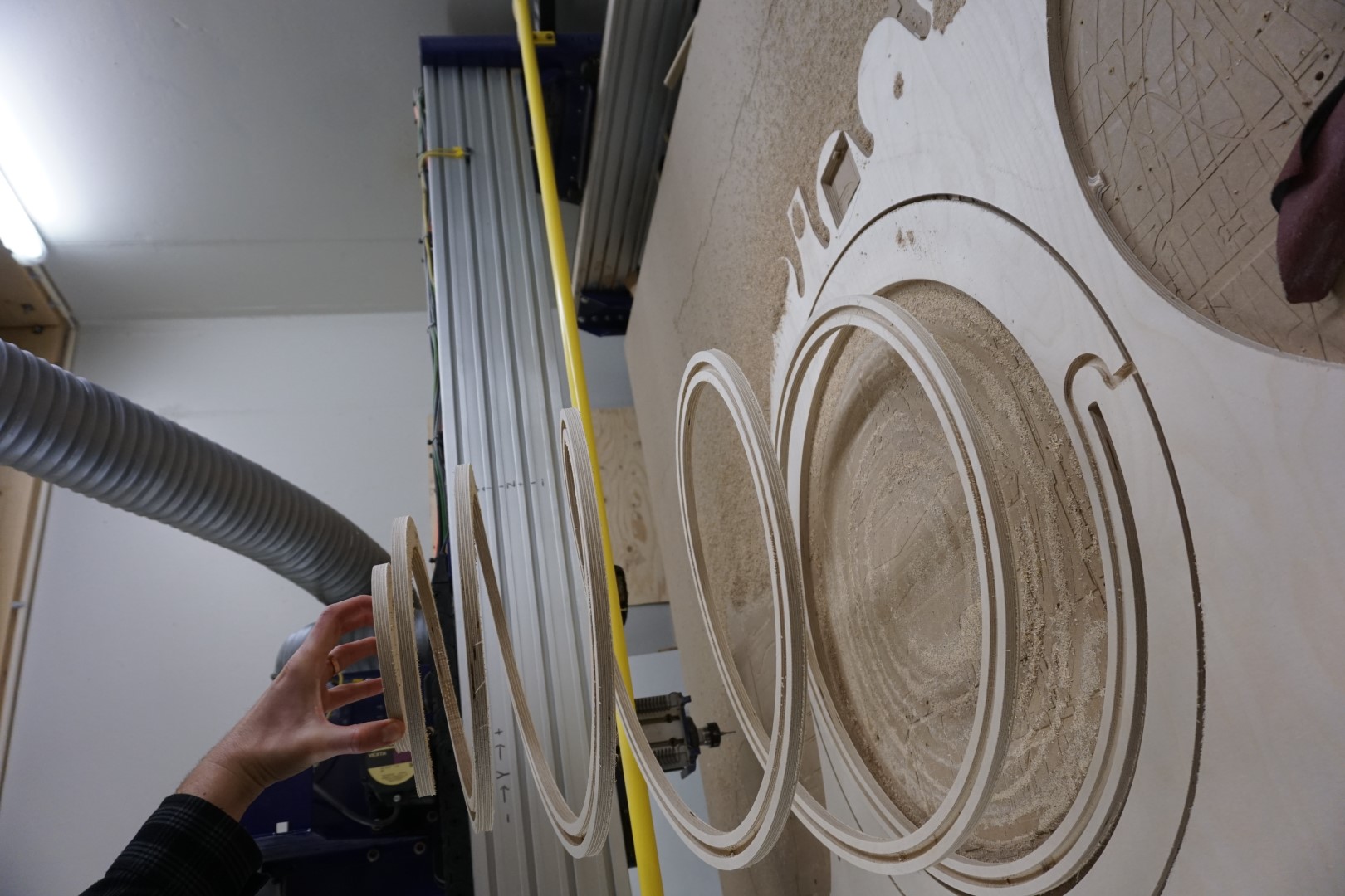
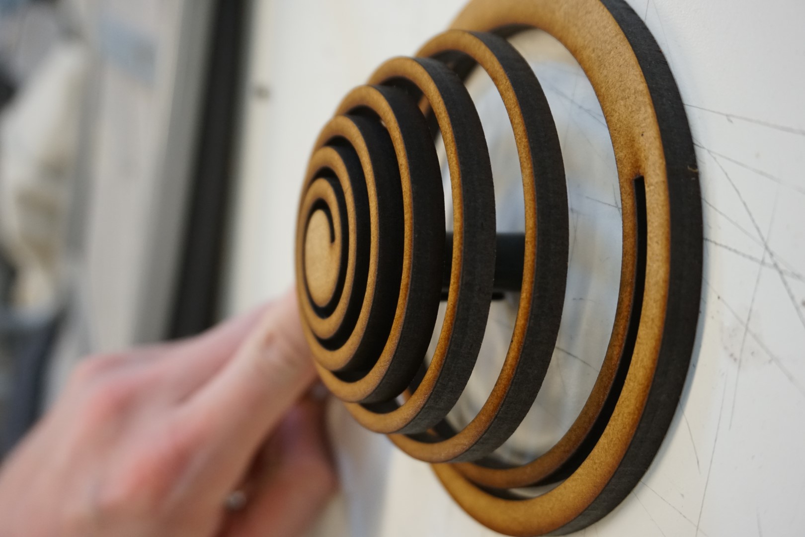
As shown in the photo above, the spiral is quite flexible. In fact, it’s way more flexible than I had expected.
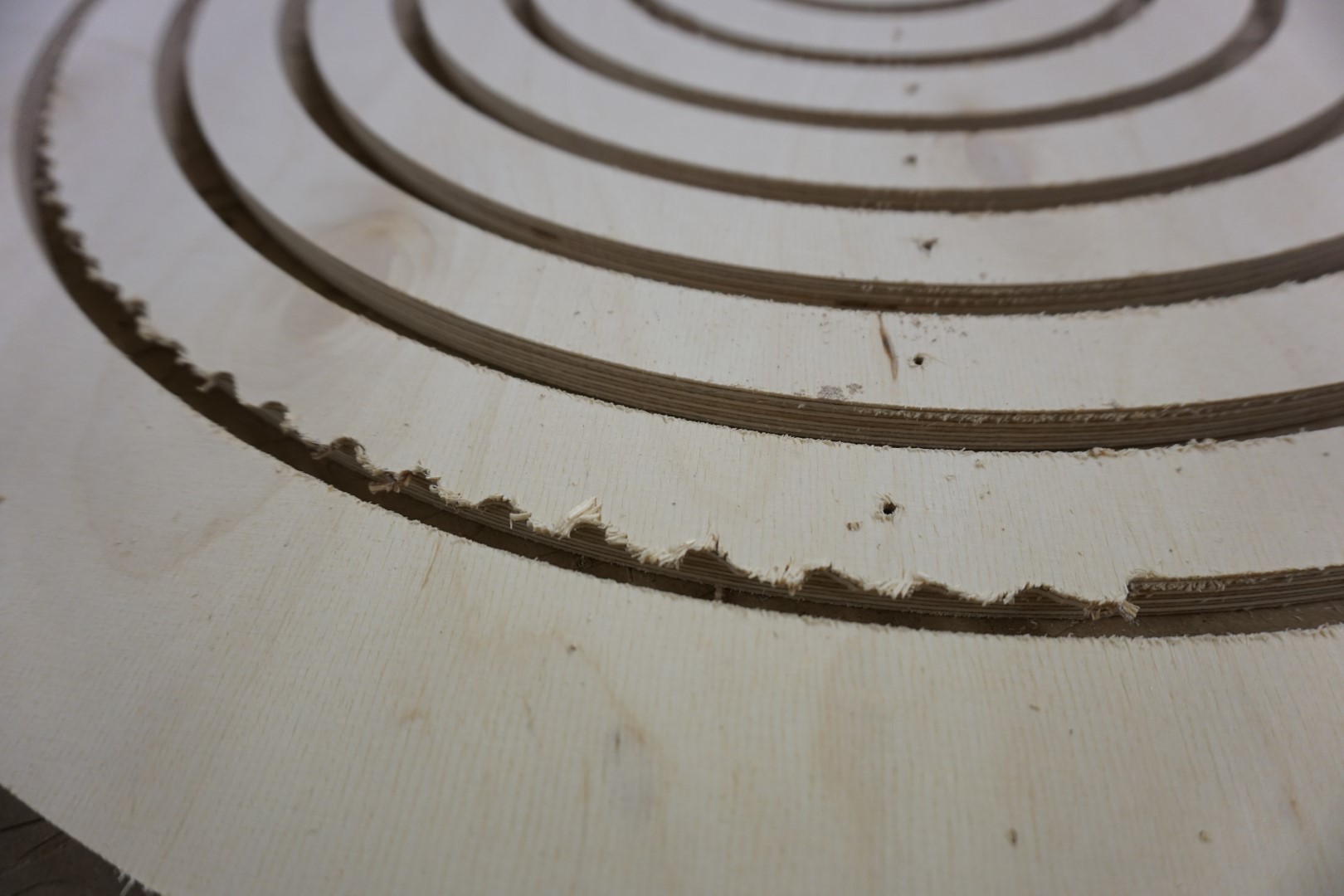
Here the damage from where the spiral vibrated is clearly visible. This can be sanded down and the end result should not suffer too badly.
Also visible are the holes left from the screws.
The cutting/mounting process needs the done differently if another piece is to be cut.
The prop-up-joint
As the spiral is meant to be mounted vertically on a wall, it needs something to prop up/out the spiral.
For this part, I added a dogboned joint and a circular wall mount to the design.
Milling
Yet again, finding a scrap piece of wood to use, I mounted it to the machine and ran the milling job. This time I used a 1/8” bit.
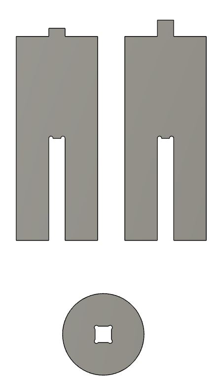
One of the joints has a small mount on top while the other has a larger one. The one with the smaller mount is meant to join with the spiral center, where the joint is a pocket but not cut through the material, while the larger one is meant to join with the wall mount.
Fail
Here I ran into a teachable moment. I put tabs into the toolpath but they were too weak to hold the circle when milling the center mount. The circle came loose and the joint was not usable.
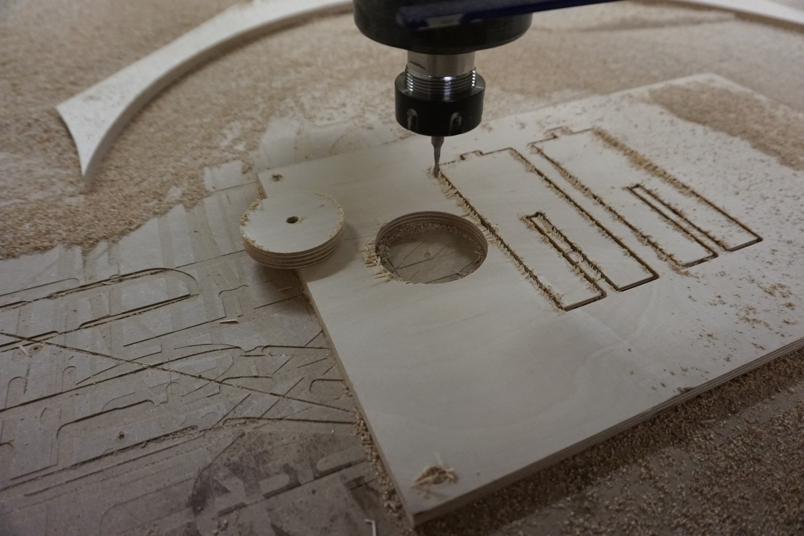
I then adjusted the program to just cut out a new circle, this time joining the two jobs of cutting the outline and the center mount, but in the wrong order! So again, the circle came loose before it finished the joint!
Again I created two jobs, one for the outline and one for the center mount. This time I made sure to run the center mount cut first, then the outline!
Success!
Finally having the prop piece ready, I could sand it down a bit and test it out
Testing the joint, it was really snug!
Test fitting the joint to the back side (not fully pressed in).
Test fitting horizontally, where gravity plays too much of a role!
And finally, vertically “mounted”, the spiral seems to find a nice form!
The CNC project itself
Judgment day
For the CNC part of this week, I’m content with this project. It remains to be seen if my instructor and Fab-Academy higher ups feel the same but I’ll await judgment confidently!
Taking it further
What remains to be done to make this a viable wall mounted light is to find a suitable light source. I’m thinking to either attach four LED strips to the prop up joint, in the crevices so to speak, or on the back side of the spiral, where the wire cut out is.
Feeds and speeds
With the tools I used above, most of the settings were defaults. One option to find the optimal feeds and speeds for the machine and tools you are using is using G-Wizard.
It is a powerful tool that can help you navigate the often complicating process of setting up the optimal milling job!
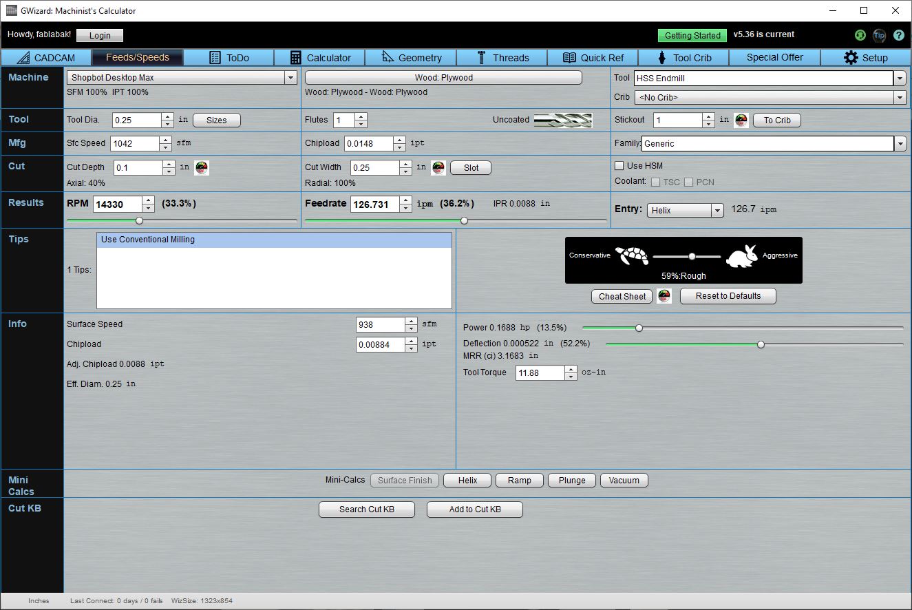
In the screenshot above, I have set up some settings to show the basic functionality. You can set the material, tool bit and the adjust the various options. It automatically calculates the impact they have, offers suggestions and highlights values that are way off.
I’m excited to try to mill aluminum and other tougher materials and once I try that, I’m certain I’ll be using G-Wizard to guide me.
Attention: You have to buy G-Wizard. My Fab Lab owns a copy.
This weeks files
| File | Description |
|---|---|
| Spiral | Fusion 360 public link |
| MDF spiral | PDF for MDF prototype |
| Test piece | Test piece(VCarve) |