13. Input devices
Hello again!
Boards and equipment
As I’m so concerned with not creating too much E-waste, I’ll be upcycling the board I made in week 11, the output device week.
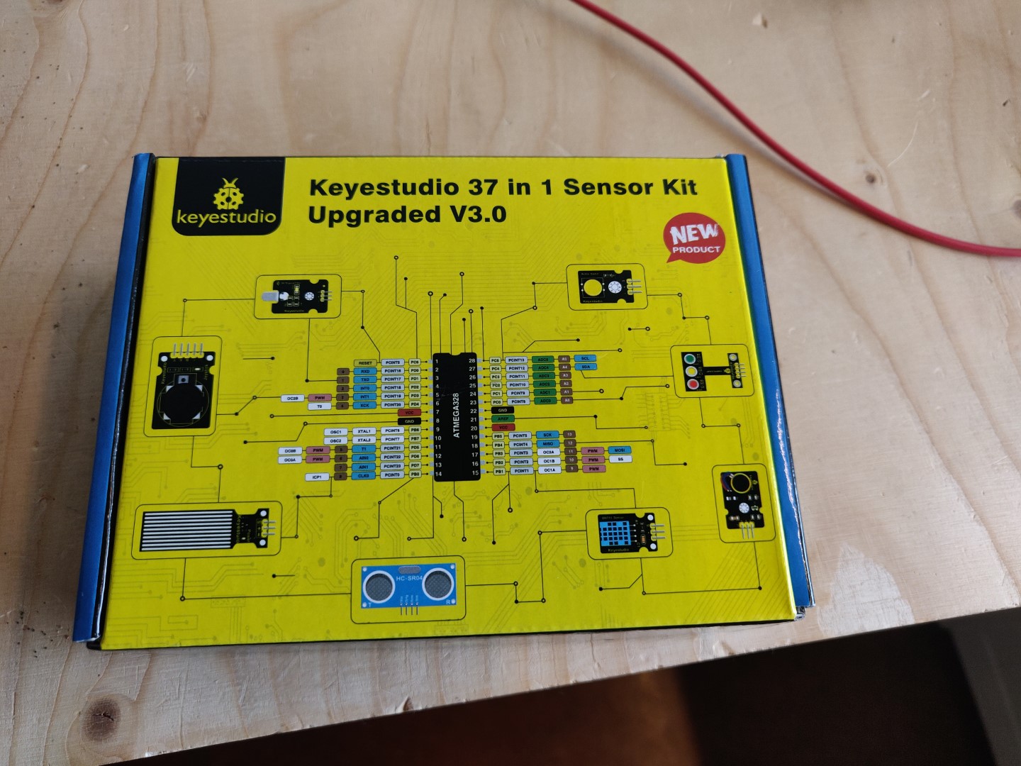
In the Ísafjörður Fab lab, I found a box containing a bunch of sensors. I’m going to test some of those sensors. This minimizes the amount of E-waste, as I can use my own board and the sensors can reused later for teaching or other projects. This makes the earth happy.
A new PlatformIO project
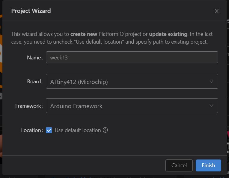
Again, I will be using VSCode and PlatformIO to write and upload the code. Like before, I create a project within the VSCode workspace and specify the ATtiny412 microchip as the target board.
As before, I modify the platform.ini file with configuration I used before:
[env:ATtiny412]
platform = atmelmegaavr
board = ATtiny412
framework = arduino
upload_speed = 115200
upload_flags =
    -d
    attiny412
    -c
    $UPLOAD_PORT
    -b
    $UPLOAD_SPEED
    -v
upload_command = pyupdi $UPLOAD_FLAGS -v -f $SOURCE
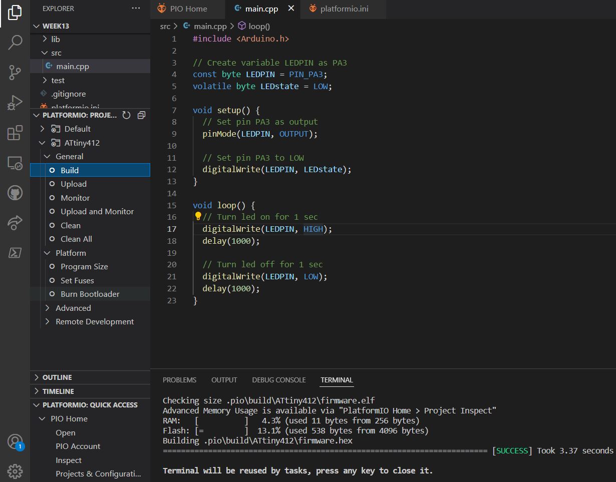
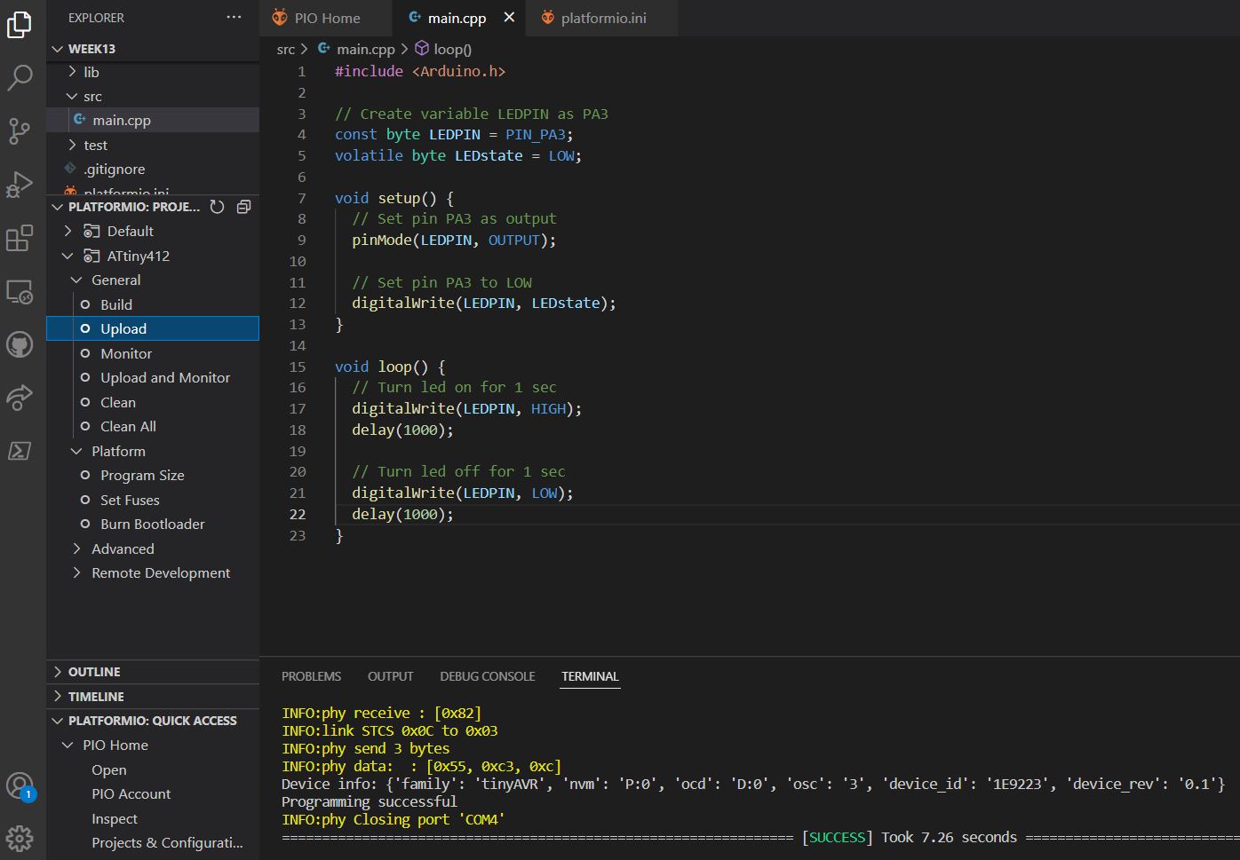
To make sure everything works correctly, I again put in a test code to blink the LED every second.
#include <Arduino.h>

// Create variable LEDPIN as PA3
const byte LEDPIN = PIN_PA3;
volatile byte LEDstate = LOW;

void setup() {
  // Set pin PA3 as output
  pinMode(LEDPIN, OUTPUT);

  // Set pin PA3 to LOW
  digitalWrite(LEDPIN, LEDstate);
}

void loop() {
  // Turn led on for 1 sec
  digitalWrite(LEDPIN, HIGH);
  delay(1000);

  // Turn led off for 1 sec
  digitalWrite(LEDPIN, LOW);
  delay(1000);
}
I hit the build command and am presented with the wonderful SUCCESS.
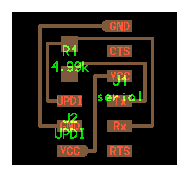
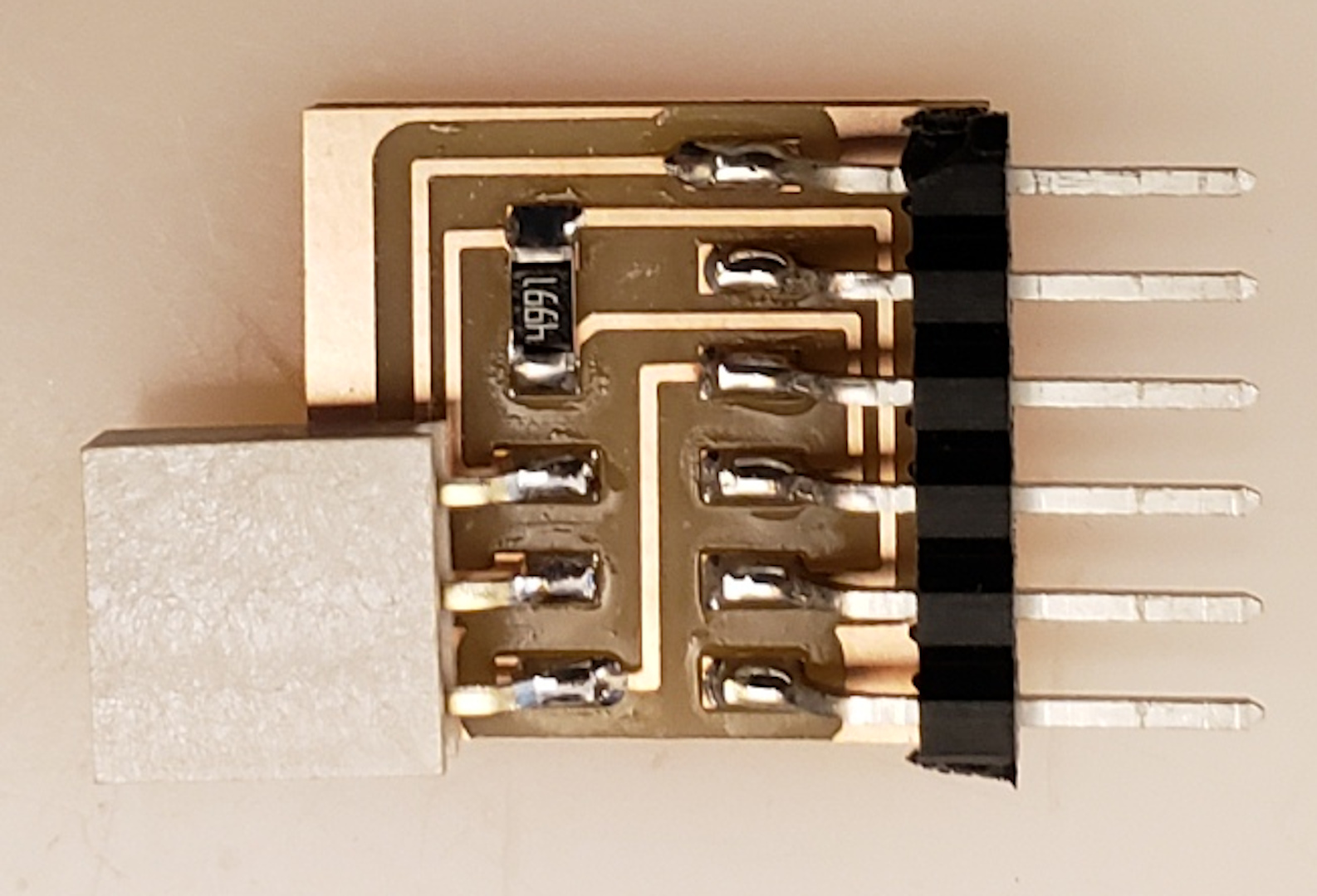
I am using the USB FTDI cable with the FTDI to UPDI converter board, mentioned on the embedded programming site of the Fab Academy. I include the Fab Academy picture and traces here for prosperity.
I hit the upload command and am presented with even more SUCCESS. How successful is this!?!
Inputs
Now, lets try some inputs!
Crash sensor
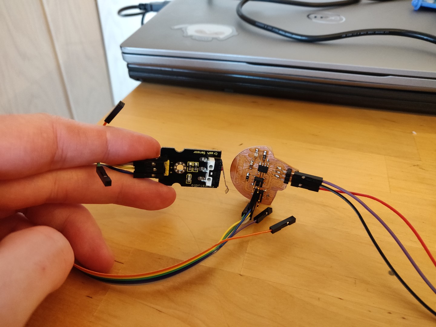
I started rummaging through the box and looking at the components. The boards have marked connector terminals, making connections nice and easy. Many of them also include a descriptive name on the board. One of them caught my eye, named Crash sensor. How interesting!
Turned out it’s just a simple switch. Let’s try it out.
Using the same pins I used for +, - and (s)ignal for the Servos in week 11, I connect to +, - and S on the switch. Then, adjusting the sample code from the site to one I had previously written, I end up with this:
#include <Arduino.h>

// Set LED pin
int LED=PIN_PA3;

// Set sensor/crash/shock pin
int SHOCK=PIN_PA1;

// Variable for reading/storing state
int val;

void setup()
{
  // Set LED pin as output
  pinMode(LED,OUTPUT);

  // Set collision sensor pin as input
  pinMode(SHOCK,INPUT);
}

void loop()
{
  // Read the value and store it
  val=digitalRead(SHOCK);

  // When collision sensor detects a signal, LED turns on.
  if(val==HIGH){
    digitalWrite(LED,LOW);
  } else  {
    digitalWrite(LED,HIGH);
  }
}
And the the glory in mp4 format:
Touch sensitive button
Next I wanted to try the capacitive touch button. With minimal changes to the above code, we can now order pizza!
#include <Arduino.h>

// Set LED pin
int LED=PIN_PA3;

// Set touch pin
int TOUCH=PIN_PA1;

// Variable for reading/storing state
int val;

void setup()
{
  // Set LED pin as output
  pinMode(LED,OUTPUT);

  // Set collision sensor pin as input
  pinMode(TOUCH,INPUT);
}

void loop()
{
  // Read the value and store it
  val=digitalRead(TOUCH);

  // When touched, LED turns on.
  if(val==HIGH){
    digitalWrite(LED,HIGH);
  } else  {
    digitalWrite(LED,LOW);
  }
}
As can be seen, it detects the touch through cardboard. This can add impressive depth to projects, by embedding buttons below the surface.
Ultra sonic sensor
Next I found this ultra sonic sensor. I’ve often seen them, but never connected them before. They are a bit funny looking, the transmitter and receiver kind of look like eyes which is fun because this module can be used to let robots detect obstacles and thus their surroundings.
I adjust the sample code to work with my board, like this:
#include <Arduino.h>

// Set LED pin
int LED=PIN_PA3;

// Set ultrasonic signal receiver pin ECHO to digital pin 6
int inputPin=PIN_PA6;

// Set ultrasonic signal transmitter pin TRIG to digital pin 7
int outputPin=PIN_PA7;

void setup()
{
  pinMode(inputPin, INPUT);
  pinMode(outputPin, OUTPUT);
  pinMode(LED, OUTPUT);
}

void loop()
{
  digitalWrite(outputPin, LOW);
  delayMicroseconds(2);

  // Pulse for 10μ s to trigger ultrasonic detection
  digitalWrite(outputPin, HIGH);
  delayMicroseconds(10);
  digitalWrite(outputPin, LOW);

  // Read receiver pulse time
  int distance = pulseIn(inputPin, HIGH);
  distance= distance/58; // Transform pulse time to distance

  if (distance < 5) {
    digitalWrite(LED, HIGH);
  } else {
    digitalWrite(LED, LOW);
  }
  delay(50);
}
Line tracking sensor
Next interesting one was this line tracking sensor. It’s supposed to be able to detect going from white to black or vice versa. I found it on the Keyestudio wiki. Again this is something I have not tested before. I grabbed a A4 printer paper and a black coloring pencil and made a box. It detected the changes when I moved it just fine!
I used the following code to test it out:
#include <Arduino.h>

// Set LED pin
int LED=PIN_PA3;

// Set line detection sensor to digital pin 2
int inputPin=PIN_PA2;

void setup()
{
  pinMode(inputPin, INPUT);
  pinMode(LED, OUTPUT);
}

void loop()
{
  // Read the input pin
  int sensorValue = digitalRead(inputPin);

  // If the sensor reports 1, turn on the LED
  if (sensorValue == 1) {
    digitalWrite(LED, HIGH);
  } else {
    digitalWrite(LED, LOW);
  }
  delay(50);
}
End of input
I’m going to call it a day for now.
Probing
Next up, a bit of probing around!
Setup
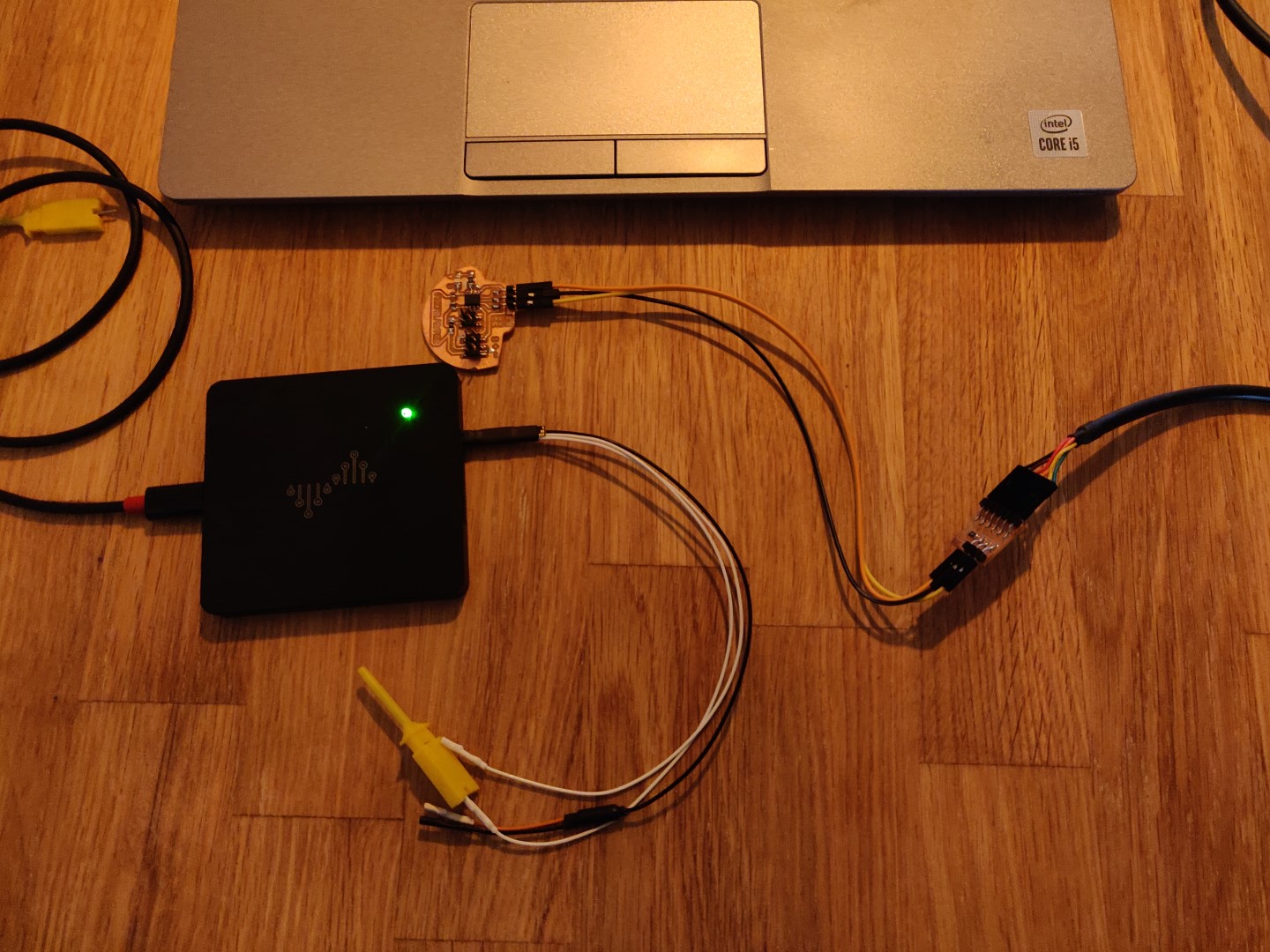
For this part, I borrowed a DSLogic Plus analyzer from my instructor.
It’s a 16 channel analyzer with a USB-C to USB-A cable for PC connection.
I fetched the latest Windows software from their download site and set it up.
Next I connected the analyzer to my laptop, along with my board and the programmer cable.
Trying it out
Since I had disconnected the last sensors I used, I figured I’d try to make some sense of the probe with just the board.
So after familiarizing myself with the layout of the software I wanted to try to take some measurements.
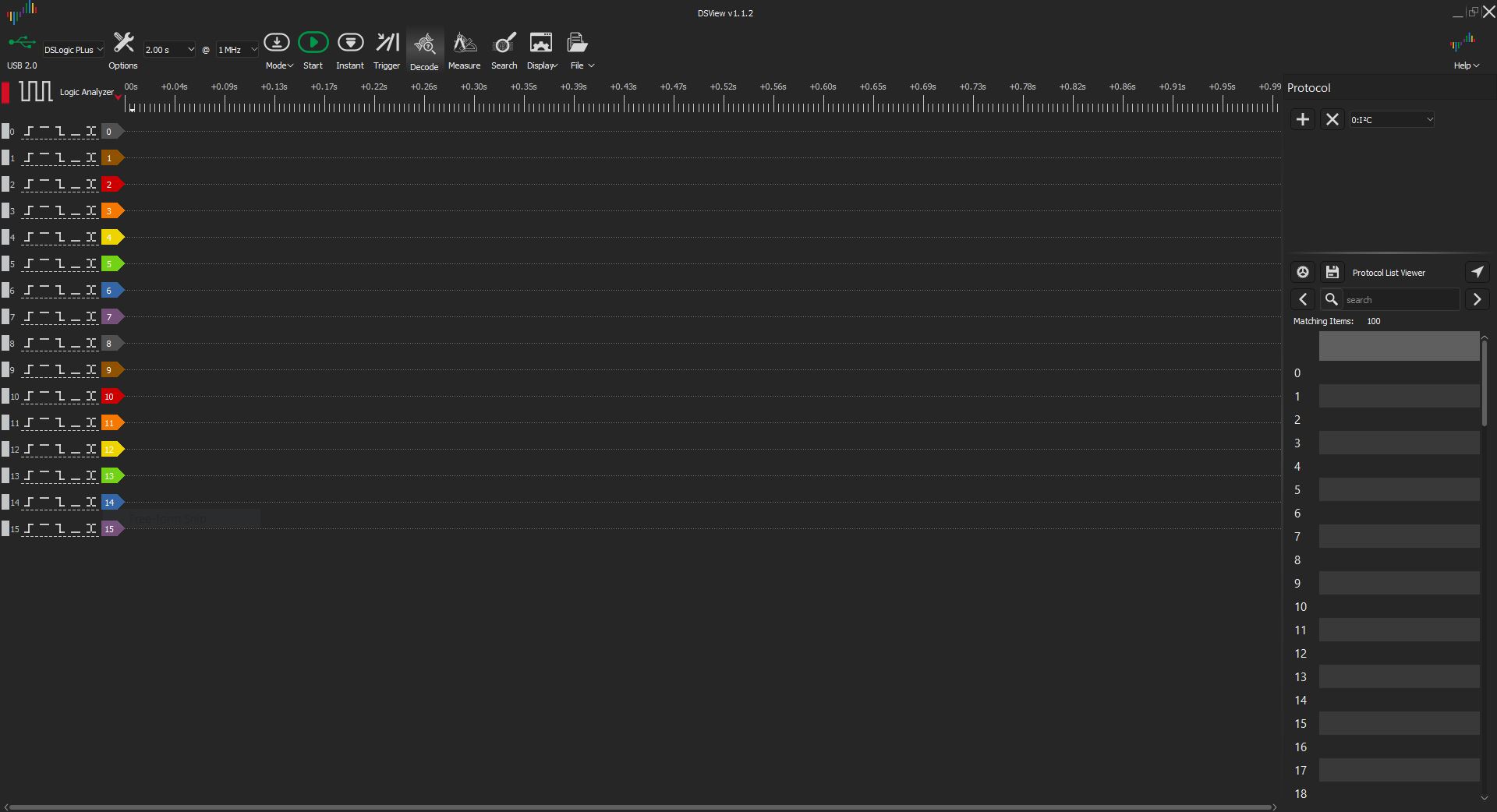
In the main area, we have the 16 channels, labeled 0 to 15.
Above the main field, we have the DSLogic Plus USB device selected, the duration (2 second) and the MHz. I left the Mhz setting at the default 1MHz.
After exploring the options, I found the PWM option within the Decode tab. I selected the PWM and the channel to measure. After a bit of testing, I found that I was using Chanel 1.
On the ATtiny412 I put the following code to test:
#include <Arduino.h>

int PWM_PIN = PIN_PA2;

void setup()
{
  pinMode(PWM_PIN, OUTPUT);
}

void loop()
{
  analogWrite(PWM_PIN, 127);
}
This is a simple PWM signal, set at half the maximum value of 255 (0-255).
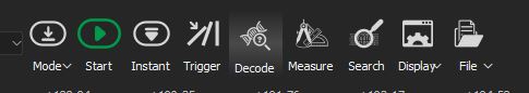
Uploading the code and connecting the probe to pin PA2, I got the following output after hitting Start within DSView:
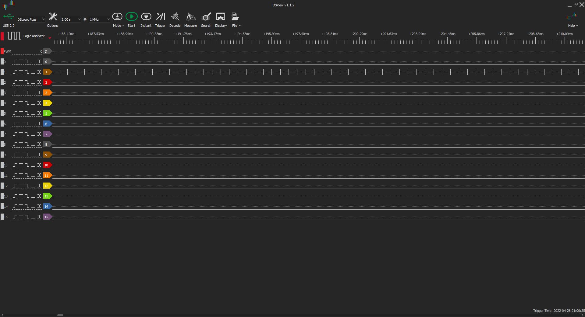
Zooming in and using the Measure tab, we see that part of a frame, for lack of a better term, has the approximately the same values or:
| Width | Period | Frequency | Duty Cycle |
|---|---|---|---|
| ~410μs | 820μs | 1.22KHz | ~50% |
So, we can see it’s actually at 50%! Neat!
Modifying the code above, dropping the percentage down from 50% to 10% or value of 25, we get the following output:

First of the frame:
| Width | Period | Frequency | Duty Cycle |
|---|---|---|---|
| 80μs | 819μs | 1.22KHz | ~9.77% |
| Width | Period | Frequency | Duty Cycle |
|---|---|---|---|
| 739μs | 819μs | 1.22KHz | ~90.23% |
10% confirmed!
Sensor and LED
Next I added this analog rotation sensor to the board. Per the specifications, the voltages from the sensor are interpreted as 0-1023. I map the values to 0-255 and write those values to the LED.
I connect the probe to the LED pin of the chip and record while I turn the sensor clockwise.
Not so informative, lets zoom in at the beginning, the middle and the end of the recording.
Protip: In DSView, you can right click and drag to select a part of the recording to zoom in on, very handy!
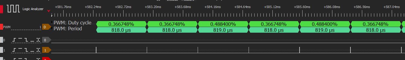
Here we are looking at some of the very first frames. As we can see on the PWM: Duty Cycle, it’s less than 1%, so not much light from the LED!
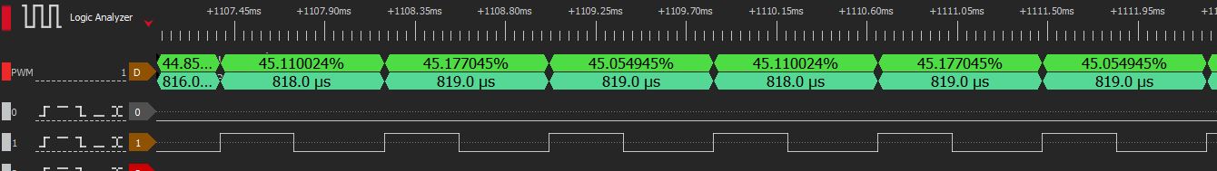
Zooming in on the approximate middle of the recording, we that the pulses and duty cycle are now around 45%. At this point, the LED is on at about half strength.

And here we are! Just about 100% duty cycle and the LED is on at full strength.
Conclusion
Sensors are fun. Probing is fun.
I need to invest in a good logic analyzer and gain experience with it when I get a chance.
Cheers!
Notes
I found this site, videosmaller.com, to be an excellent tool to compress videos. VLC gave me a bit of trouble compressing videos so for the last video I tried this site and it compressed the file from 14.27MB to 267.56kB, or by 98.17%.
This makes GitLab and Neil happy.