3. CAD: Computer aided design
This week’s mission is to learn how to use CAD software to design and build objects. I aim to test different CAD software and see how they work. I am familiar with some of them, but not all.
I followed along with the Wednesday lecture and alongside work, I tried to attend the Central European workshops and caught some introduction into FreeCAD and OpenSCAD.
My instructor laid out the weeks mission as so:
- Vector image of last week’s sketch (with possible updates/ideas?)
- Model a simple part in multiple 3D programs
- Find grab cad model
- Render in blender
- Edit in photo editor
First mission: Vector of the sketch
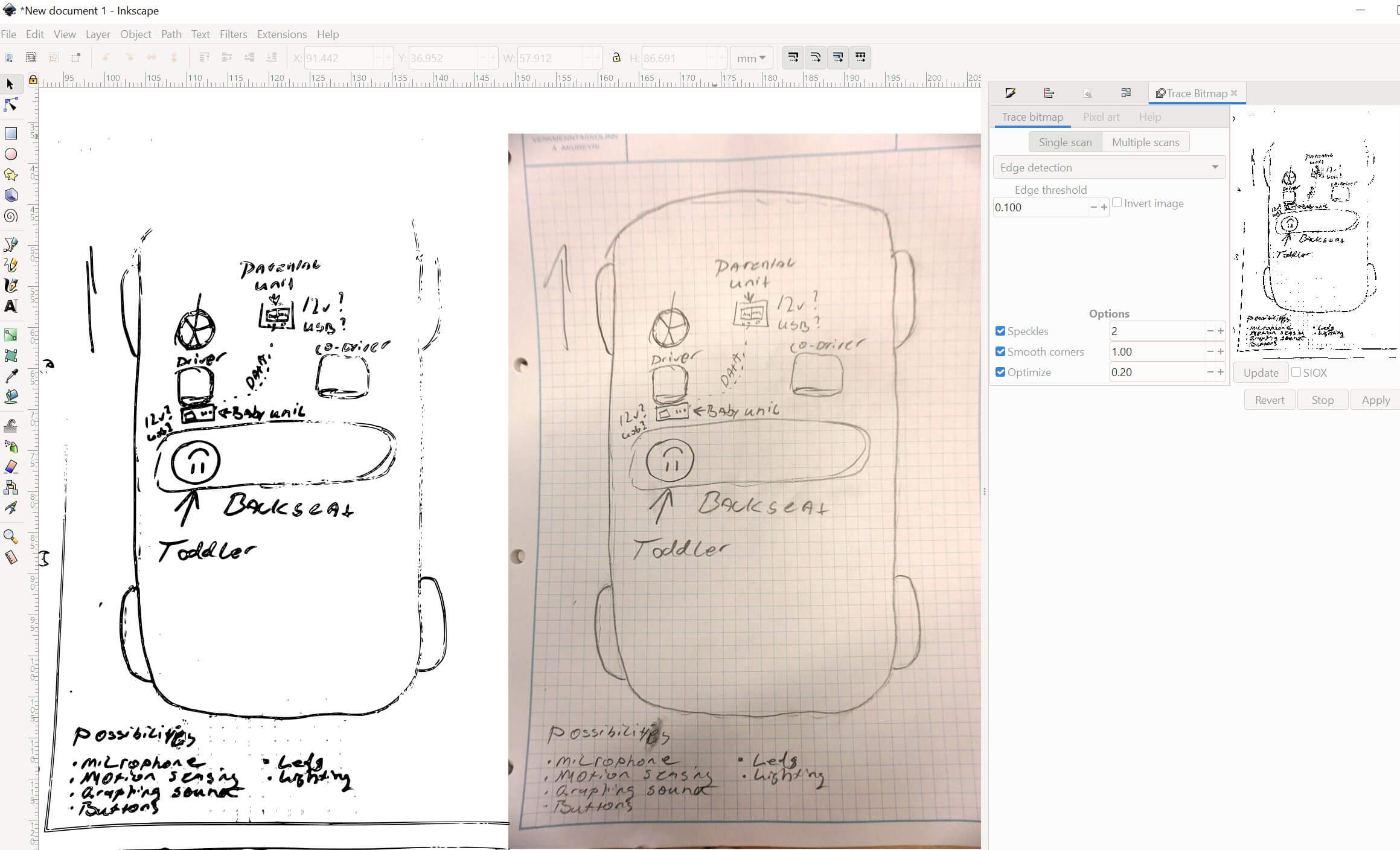
I’ve never really imported an hand-drawn image to a computer before, at least not to do any work with it. The thought has often crossed my mind though, so now I wanted to test it.
I used the image I took last week and imported it to Inkscape. I used the trace bitmap tool to trace the image. But no matter what I fiddled with the settings, it did not turn out great.
But now, the first batch of problems!
Saving for web
Oh boy oh boy!
Neil has put heavy emphasis on compressing images. Before I have written my own bash scripts for that exact purpose so I wanted to check something else out. I recall that Photoshop had a save for web function but I do not have Photoshop on my computers. I opted for Gimp, which I have only used a little.
I googled Save for web gimp and found a match, Save for web - Plugin.
But, OH NO! 404 which is computer speak for file not found. Turns out the so called plugin registry for gimp is dead?
But at the bottom it said that there is an old backup on GitHub.
When I navigated the repo, the list of plugins was truncated and I could not find the plugin I was looking for. Turns out there isn’t a nice way to get the whole list in the browser so I cloned the repo on my Windows work computer.
Oh no!
I tried the suggested command: git restore --source=HEAD :/ which gave me a ton of errors like: error: invalid path 'registry.gimp.org/user/login?destination=comment%2Freply%2F9129%23comment-form'
Oh come on!
So switched to my Ubuntu virtual machine and cloned the repo, it was a success.
I entered the files directory and using ls | grep save I found the plugin.
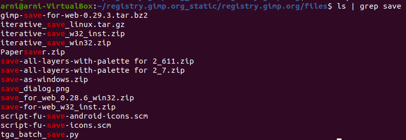
I installed the plugin per the README, simply extracting the .exe to the plugins directory.
After turning the quality down to 70% and testing a few settings, I saved the image and checked the results.
| Image | Size |
|---|---|
| Before | 1880 KB |
| After | 310 KB |
Comparing the images I saw no difference.
Great success!
On the the vector work.
Using a thicker pen and a paper without any background lines, I doodled a new sketch. I photographed it with a DSLR that I have dedicated to my Fab Academy work.
I imported the image into Gimp, rotated it, cropped it and touched it up a little.
Vector scan outcome
Then I imported the image into Inkscape and used the Trace bitmap function on the image.
This resulted in a much nicer vector image!
Below is the vector image I created. I was curious to see if simply pasting the code into the .md file would work. Well, it did! But since I have modified the site to have a dark background, the image did not display nicely. So I checked if the svg tag had a background property and it did! This grew the .md file to ~ 1.8 MB, which is the size of the SVG, since it’s simply text.
Just for fun, I used wc -m sketch.svg to count the number of characters in the file: 1.907.176 characters!
Input from instructor
My instructor was happy with the experimentation but gave the following pointer:
- When using the
Trace bitmapfunction, at least for this particular case, use theColor quantizationand set it to a low value.3gave a good result. This will remove gradients and create solid lines.
This provided a much better result, lesson learned!
Additional mission: Create vector image of final project
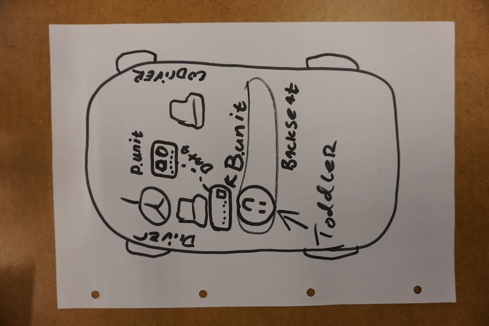
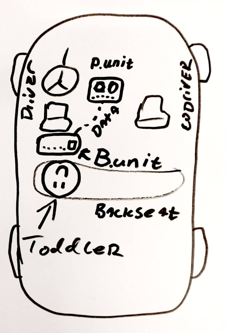
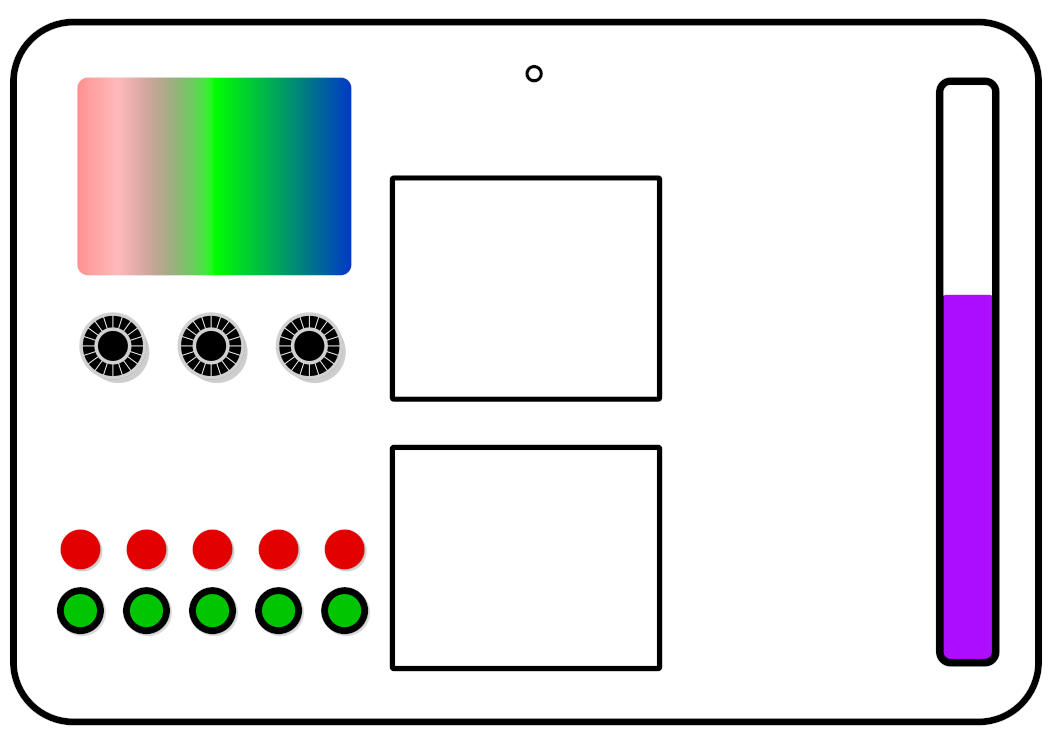
For this part, I created a vector image of the child unit of my final project. I use Inkscape for this work. It’s not intended as something finalized, but will hopefully act as a inspiration for thing to come.
It’s crudely made in Inkscape. Top left shows controllable RGB leds/strip/screen. Knobs below reprisent R - G - B.
Below that are buttons to play lightwar, where parental and child unit fight to turn leds on/off.
In the top middle is a mic input. Below them are screens showing Gyro and soundlevels.
On the right is a countdown/timer that displays travel time to child (controlled by parent unit).
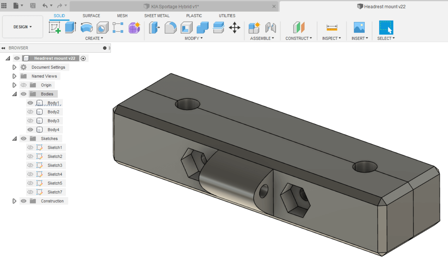
Second mission: Design parts in 3D programs
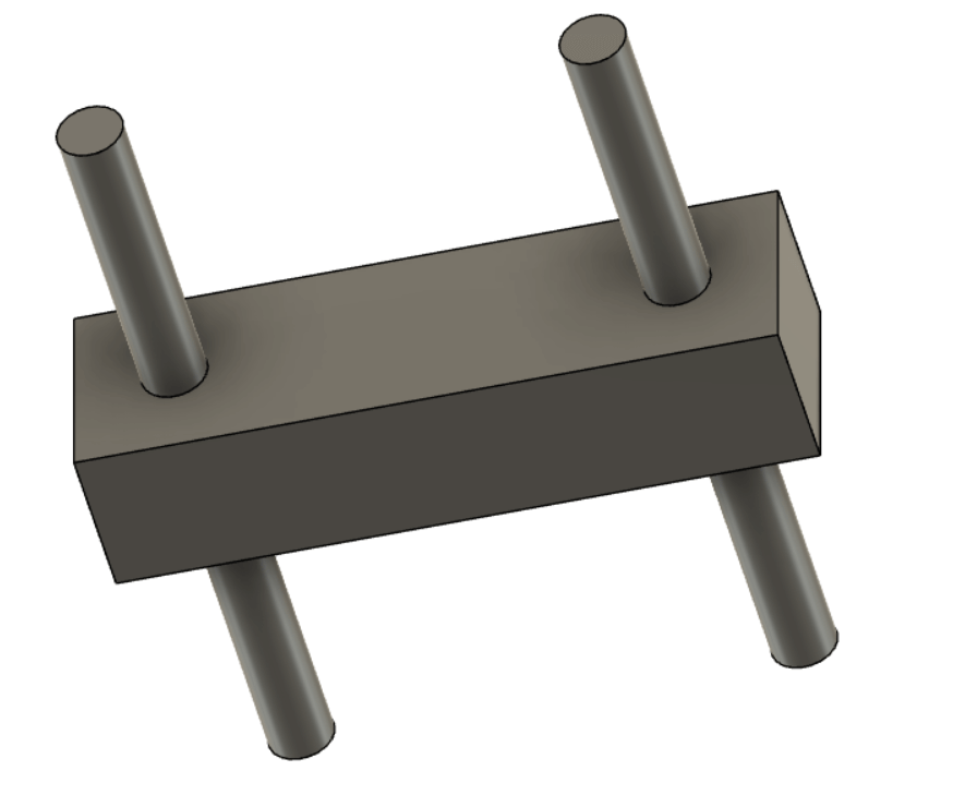
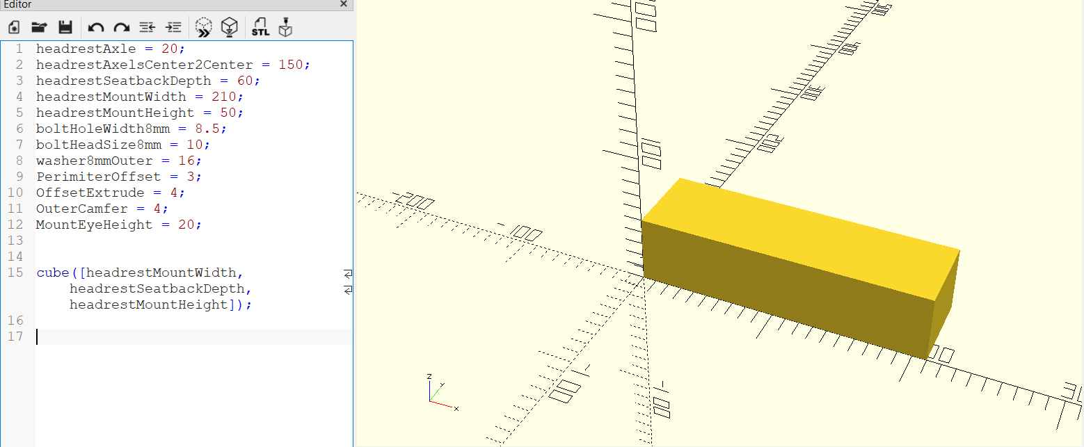
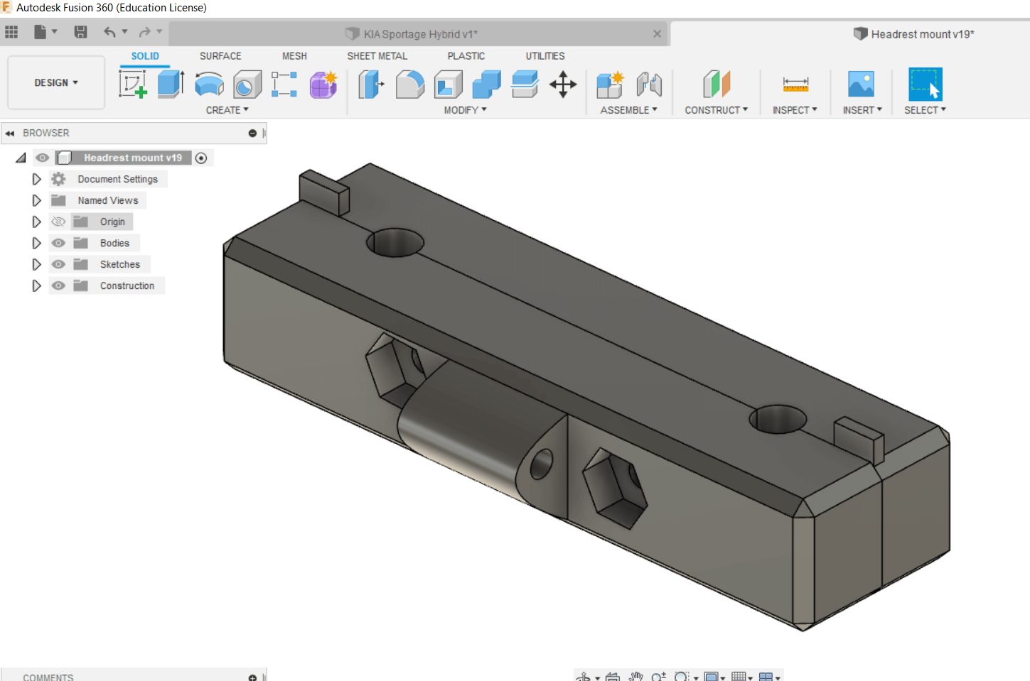
I started by using Fusion360 as I have some experience with it. The thing I start by making is something that might be useful for the final project. The units will be mounted on the back of the drivers seat and somewhere in the front. Final configurations/measurements are not ready so I thought this would be a good example of a parametric design.
The goal is to design a headrest mount for the unit. I’ll start with something basic but with parameters, so once I have a chance to measure the headrest properly, updating the design should a breeze.
The axles represent the steel rods that adjust the height of the headrest.
Below is the first fusion sketch, using only parameters.

Then, after extruding the basic form.
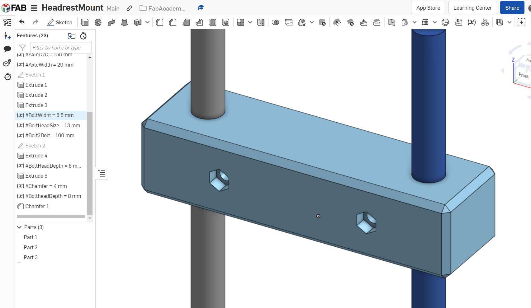
The model after countersyncing for the bolt heads and nuts (on the other side) and splitting the body.
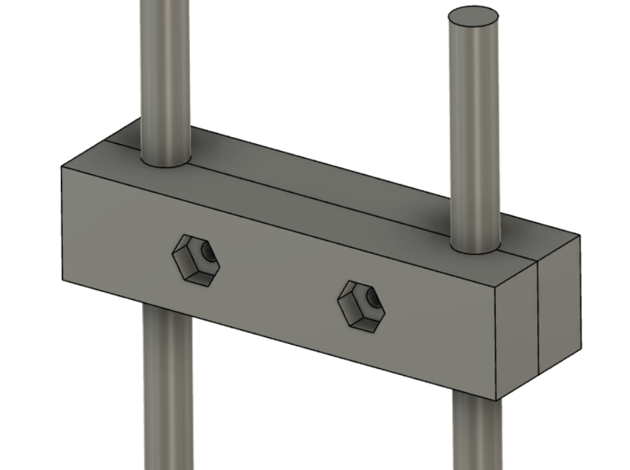
After splitting, I made a rim on the faces that meet, extruded outwards on one body an inward on the other. That way they should hold together somewhat nicely.
On the body that should face the child, I added a mount in the center for the child unit.
As a last touch, I chamfered the outer edges.
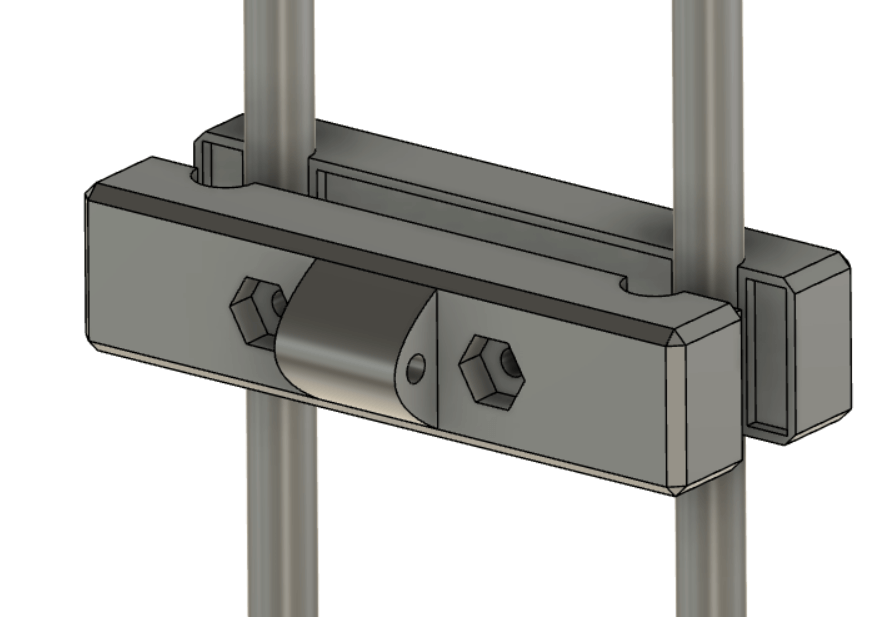
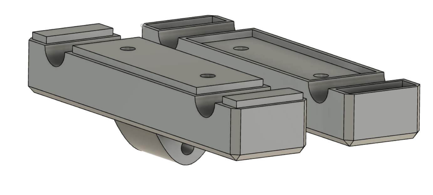
Last view, layed down showing the faces that meet.
My Fusion360 file (6.feb 2022)
That’s it for now with Fusion 360. Next up, something different!
OpenSCAD
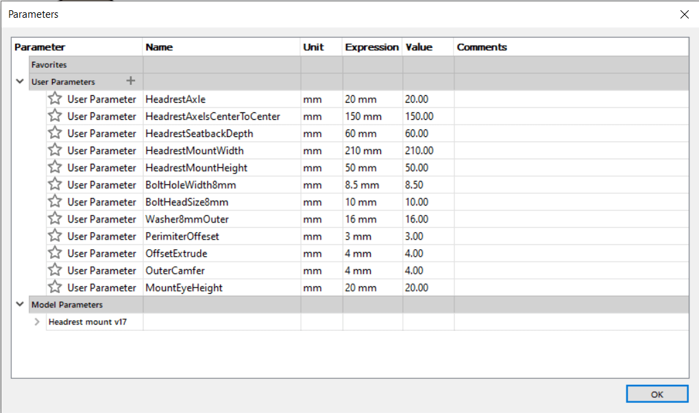
I saw a bit of the OpenSCAD extra lecture and found it interesting. Since I used parameters in the last design, I figured I’d give OpenSCAD a go with parameters. Below are the parameters from the previous design.
First OpenSCAD problem
I started setting up parameters and when I saved the program ran into a path problem. I had saved the project in my Onedrive folder, whose path includes both spaces and special characters (default from my organization!). When moved to a folder on the root of C-drive, saving worked properly.
After just a short bit of trial and error I got going. I created a box, simulated the holes for the axles before rotating and adding bolt holes and hexagonal counter syncs for the bolt heads.
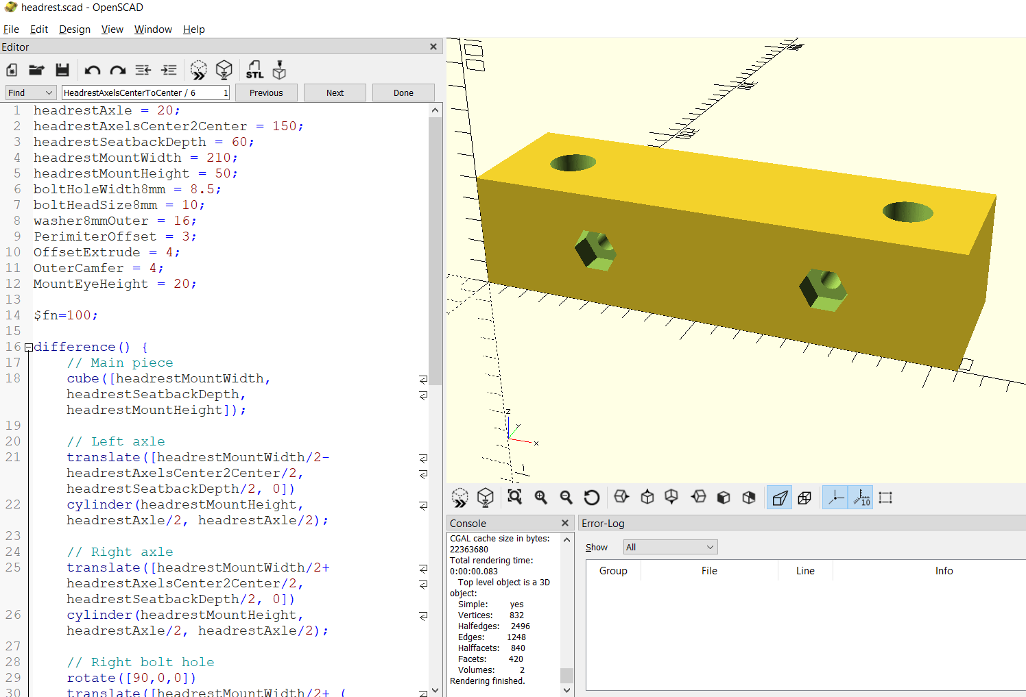
I decided that this was enough testing of OpenSCAD. I quite like it, it definitely does require a different mindset than CAD programs that put drawing first. But I can certainly see that it can be a smart fit for certain problems.
My OpenSCAD file (7.feb 2022)
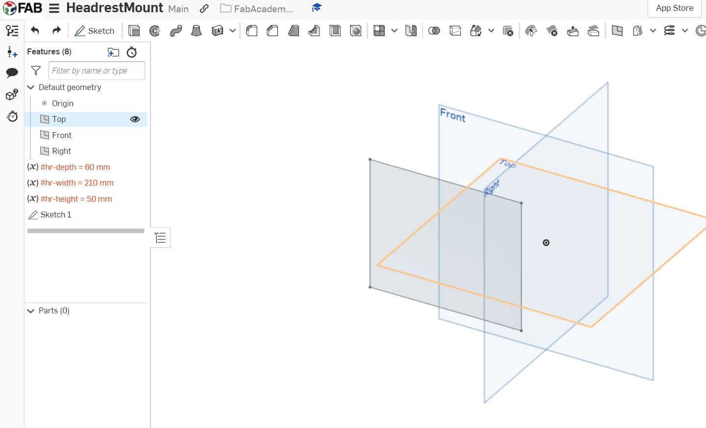
Onshape
Next up, Onshape. I recently heard about this at work. One of the teachers mentioned this to me. Anyways, I signed up using fab.onshape.com and created a new folder and a document inside it. So far, so good.
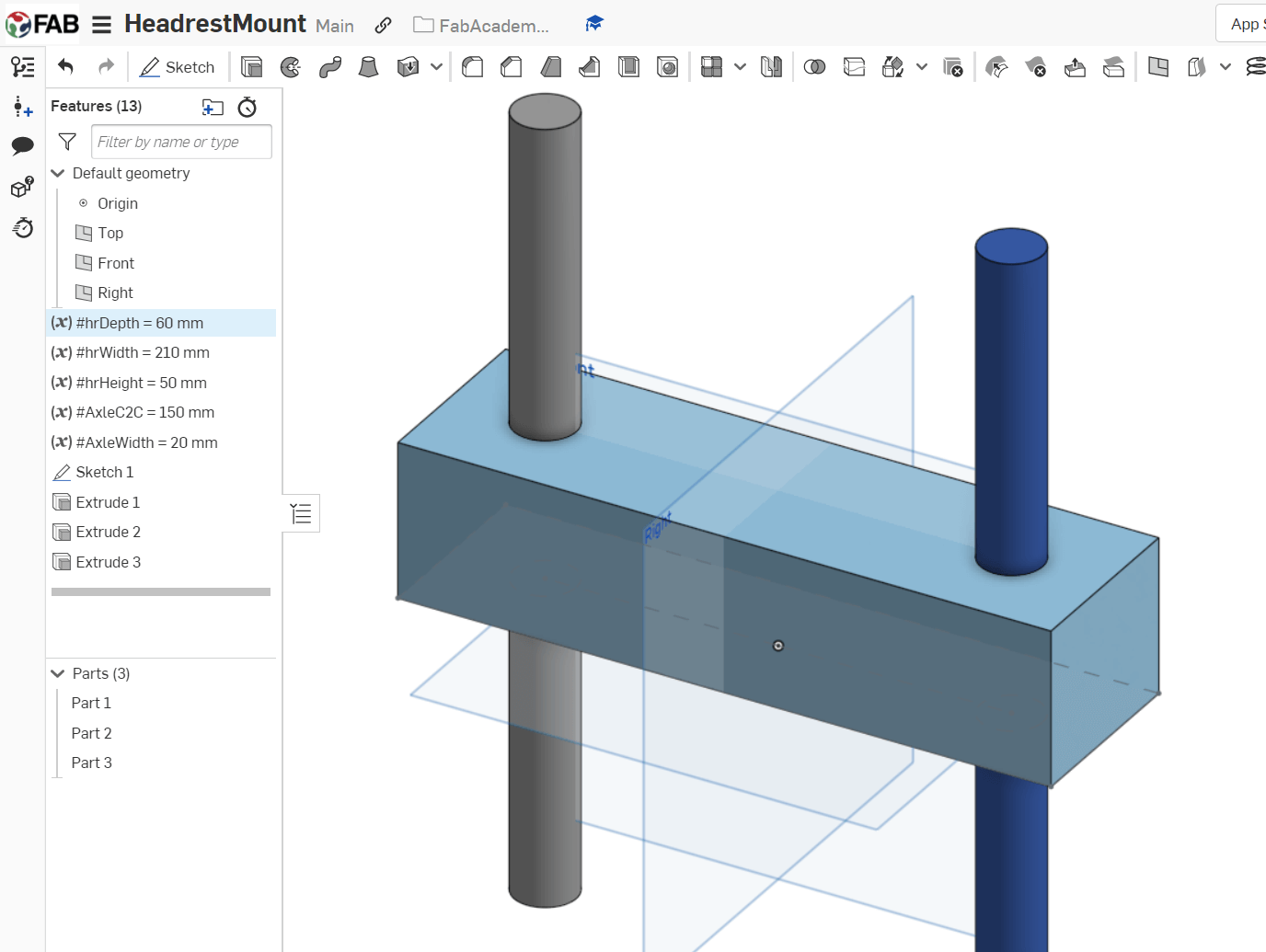
Before started, I wanted to see if I could continue using parametric design. So I quickly found the variables option and put in height, depth and height.
First trouble
I had some trouble trying to use the variables. I created a rectangle and wanted to set the dimensions to the variables, but had no luck. That was until I noticed the actual variables were marked in red, as shown in the picture.
Turns out it was the ‘-‘ I had put in the variables name. I shortened headrestMountWidth to hr-width. Changing that to hrWidth increased happiness!
After finally figuring out how to add dimensions to sides/objects (pushing the d key or using the dimension icon!) it was smooth sailing! I find the look and feel quite similar to Fusion360.
Finding a flaw and possibly contracting COVID-19?
I continued adding variables and testing the software. I find it to be really nice, quite incredible considering it being completely in browser. My laptop is no powerhouse but it seems this takes less resources than having mkdocs serve running in VSCode.
At this point I’m happy with the results and I discovered a flaw in previous designs. I had used 10mm for the boltheadsize variable both in Fusion360 and in OpenSCAD. That’s wrong, as it should be 13mm. In Fusion360 it was also assigned as radius of the bolt head size, instead of diameter. In both designs, thanks to the parameters, fixing this is really easy.
So whats left here is to split the body and create the strengthening form to the mating faces.
But since I’m currently sick (possibly covid, waiting for a test), I’m very happy with this outcome (and finding the mistake).
CAD model
First stop was GrabCAD, which my instructor recommended. I had never heard of that site before.
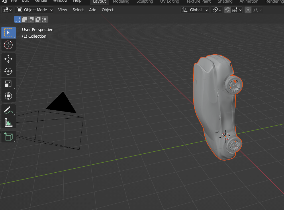
I grabbed a car model and found that it it’s a step filetype. I had never worked with a step file before, so I Googled that it opens in Fusion360. Once my computer had finished loading the model I found that it seems to be modelled as Kia in freefall =)
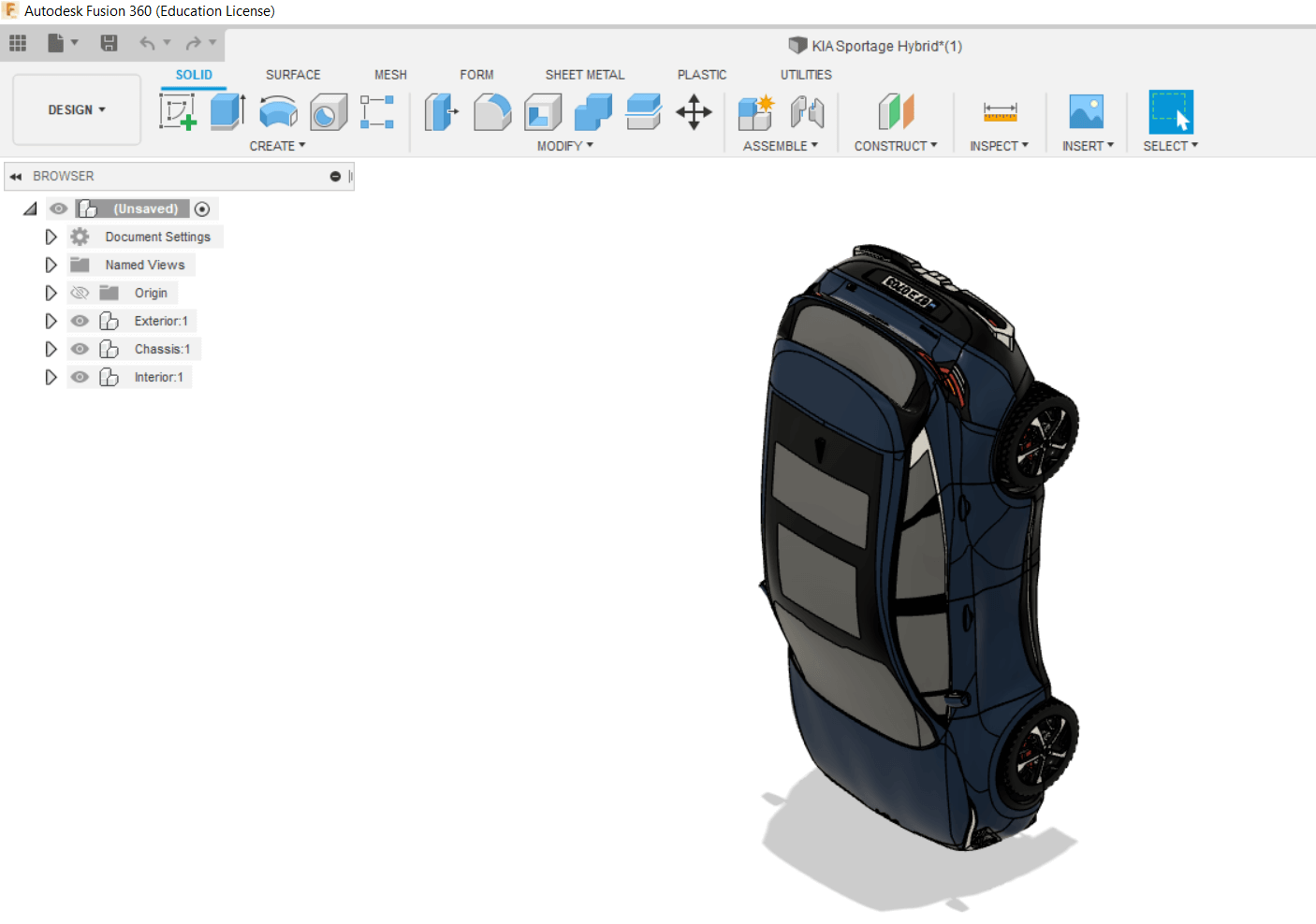
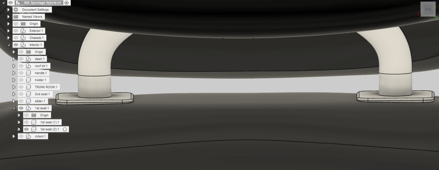
This is where things got interesting. The model is divided into Interior, Exterior and Chassis.
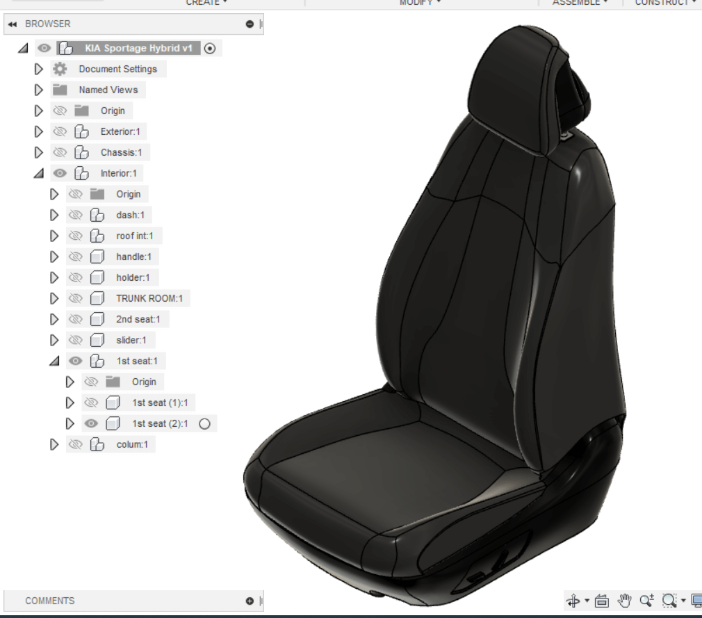
Furthermore, the interior is divided into many components so that I could hide all items other than the drivers seat.
So for fun, and so that I don’t have to wade the deep snow right now, I’ll use this newfound information to update my parametric headrest design!
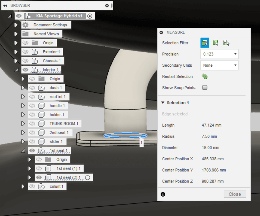
Zooming in, I got this nice view.
Using the Inspect tool, I got nice measurements.
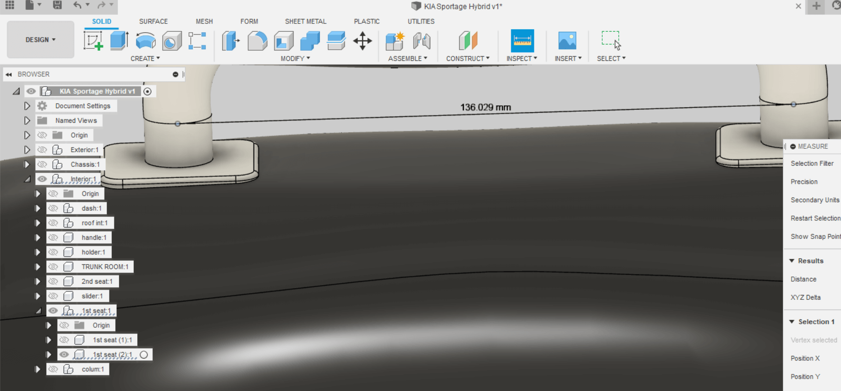
Updated measurments
| Dimension | Before | After |
|---|---|---|
| Height | 50 | 40 |
| Axle | 20 | 15 |
| Axle2Axle | 150 | 136 |
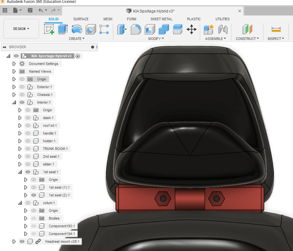
Uh oh!
Turns out I need more exercise in parametric design and CAD over all. Once I updated the parameters, the model was mostly good, but there were faults. I guess most of them are related to mixups when using projections that then get messed up when I change parameters. This is something I need to practice more, but it shows the importance of parametric design over non-parametric design.
Main faults are:
- Two parts protruding out of the joining faces.
- Bolt holes have turned
- Mount is skewed
Quickly fixing these things, the model was good enough to continue.
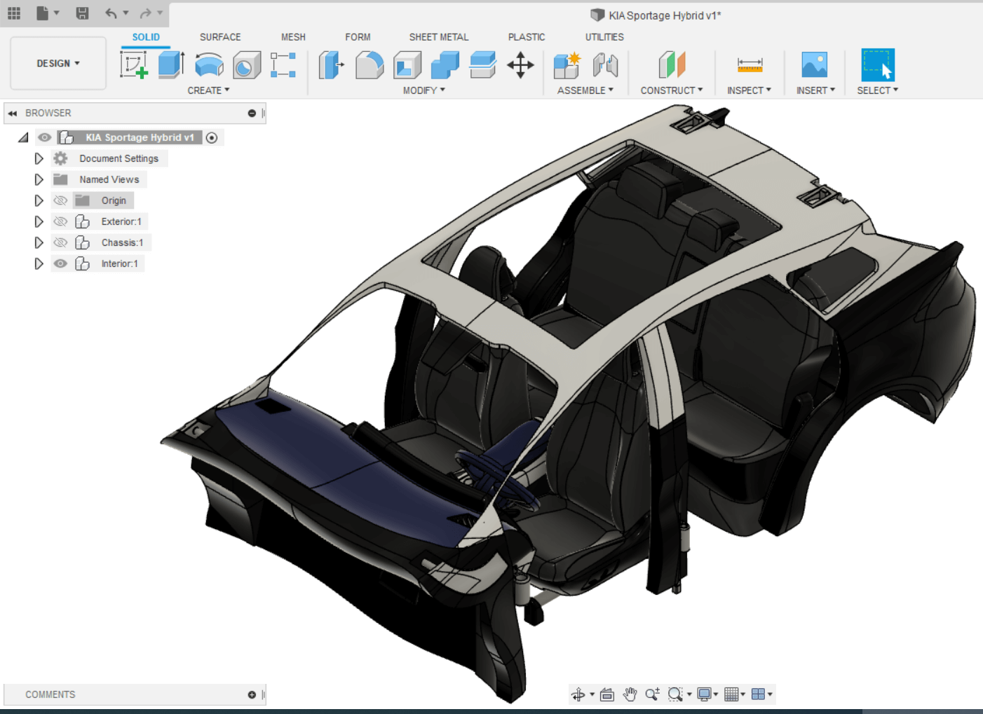
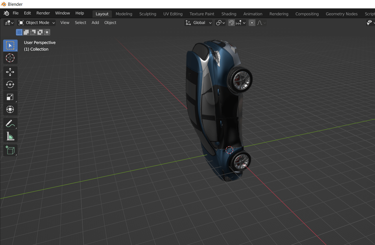
Now for the really interesting stuff! I loaded my model into the Kia model and arranged the mount on the headrest axles!
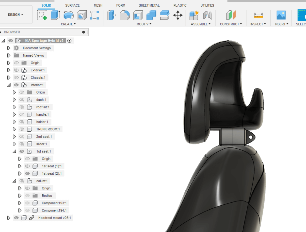
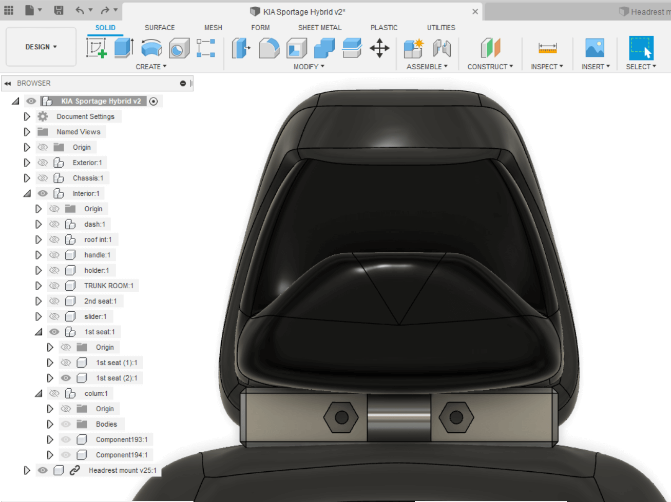
In my original model, I added a red plastic texture and simply updated the version in the Kia model.
I then un-hid all the items in the model and exported it as a .obj. This required a cloud upload/convertion which probably took good 10 minutes.
I link to the public project instead of providing the download file, since it's size far exceededs the storage constraints of the Fab Lab repo.
Blender
Finally, it’s time to try out Blender. When importing the .obj file, it turned out to be huuuuge. A quick search taught me about the clamp setting, which is a scaling option. I set that to 20 and imported again, with success.
No textures!
Well, what I learned now is that the textures did not import with the model. After a discussion with my instructor, I exported the model from Fusion again, now as a FBX filetype. Again the cloud conversion took quite some time, so having knowledge of which filetype you want to work with is good.
Again I imported with clamp set to 20.
First thing I did then was to rescue the vehicle from freefall and place it on the ground.
I then positioned the camera so that it pointed into to rear right passengers windows and hit F12 to render.
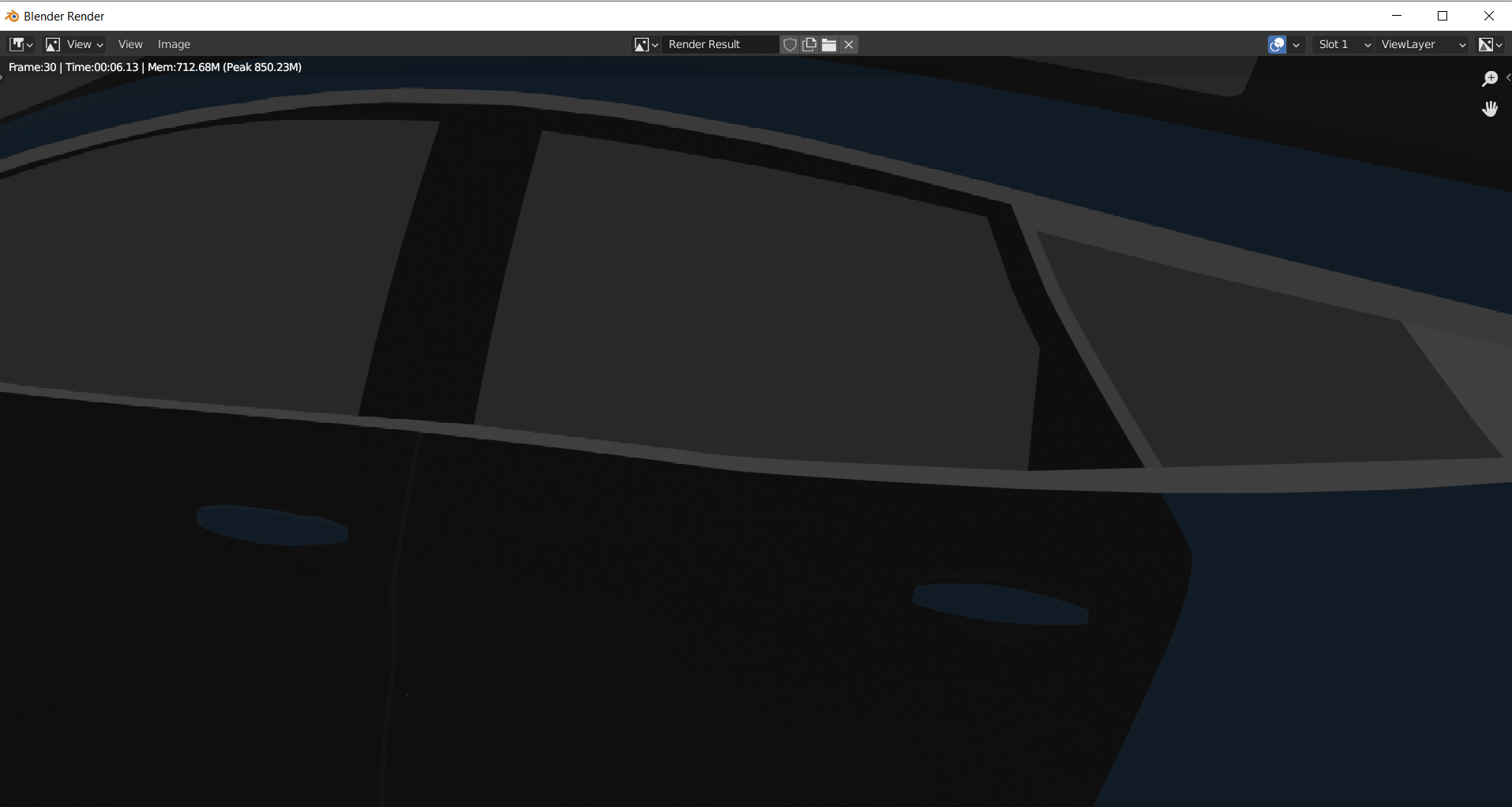
A bit of a disappointment that the windows are opaque (also a huge safety issue, we should let Kia Motors know).
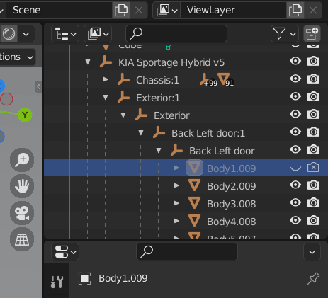
But drilling down in the models components, I found which item is the back window and hid it. This put the headrest mount in plain view, which was a delight. This also shows the importance of structuring models and having a good naming convention for components.
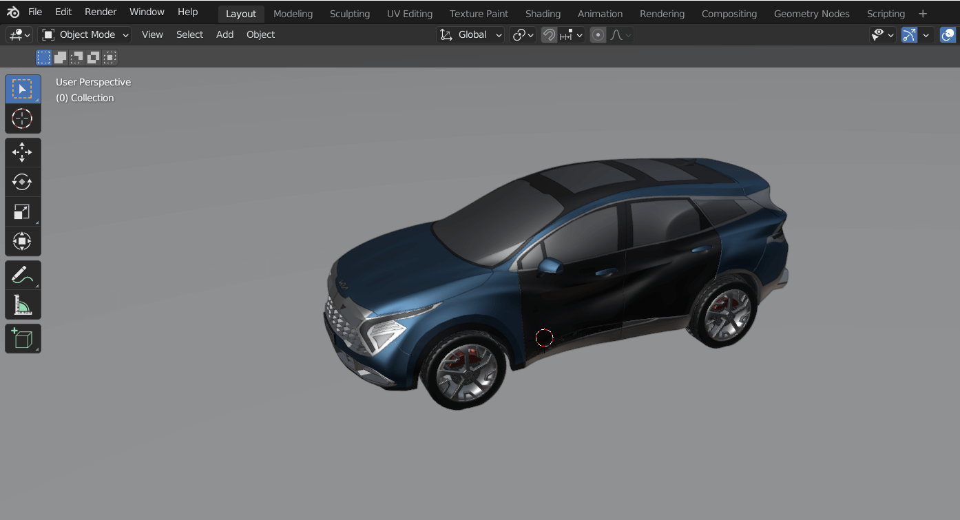
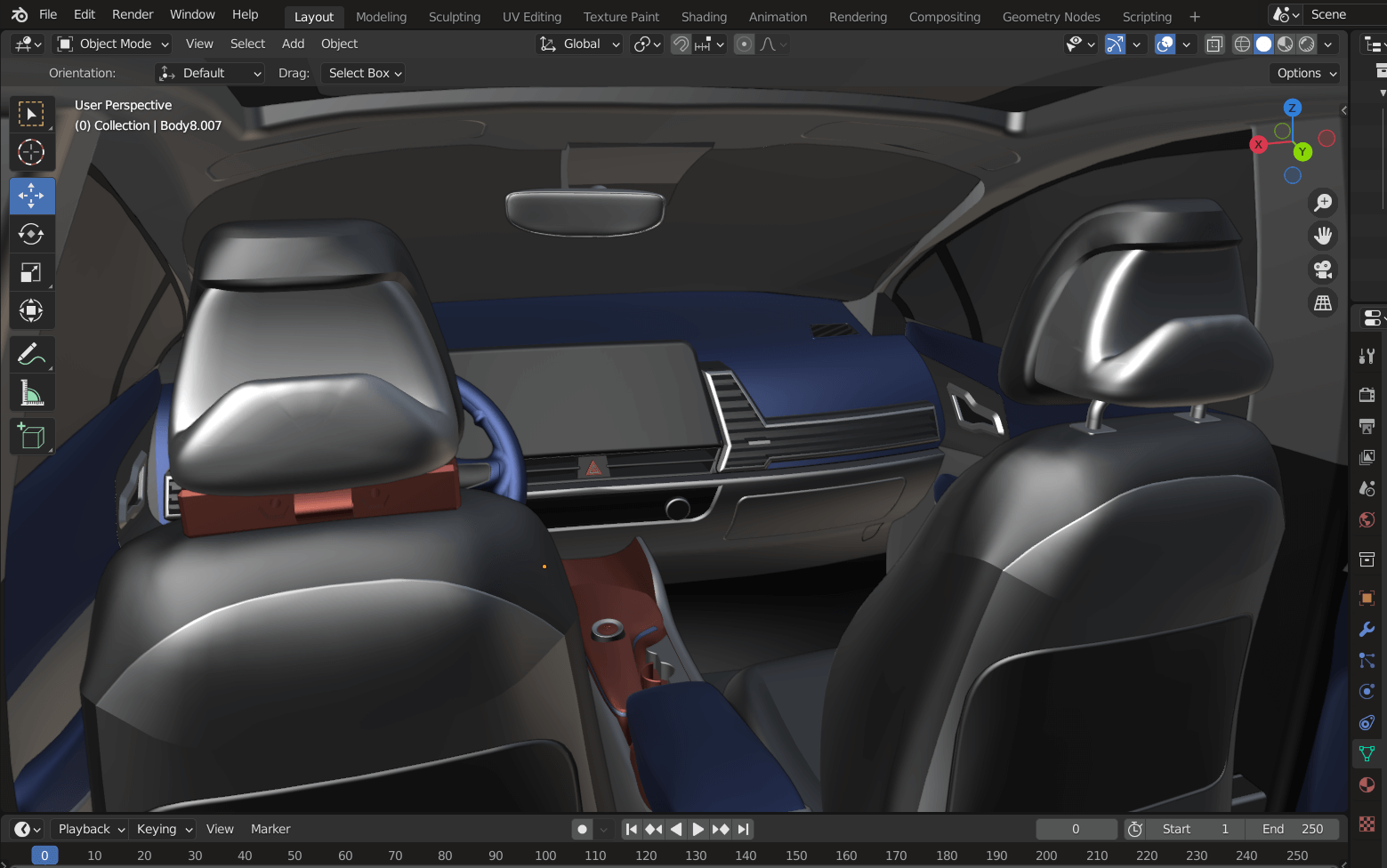
I repositioned the camera and tried adding a new light source but no luck, the renders turned out ugly. The layout view is better, I’m not sure if the is a issue with the model/software (doubtful) or the user (highly likely).

I’ll include a screenshot of the layout view in Blender, which actually much nicer.
I do not include a download link to the Blender project, for the same reason with the Fusion 360 project. It’s around 100mb in size!
Btw, using this all only with the touchpad on a laptop is faaaaar from ideal!