6. 3D Scanning and Printing
Previous work
The 3D printers in the lab are probably the tools I’ve spent the most time on since I started working here. When I started, we had two Ultimaker 2+. They are pretty old and worn and we spent a long time trying to get them to work properly.
One of the things I did, was to install OctoPrint on a spare computer, hoping to get more milage out of them. OctoPrint turned out to be quite the nice tool for us, but we wound up buying a new Prusa i3 MK3S+, what a machine!
Nice features of this printer include:
- Filament sensor to detect filament run out or is inserted
- Power loss recovery
- Automatic bed leveling
- Very detailed and fun instructions, if you select the DIY assembly kit from the maker, which saves you a few bucks.
We own the multi-material addon but we have yet to install it. We made a dry box for filaments and attached above the printer. When we have the multi-material addon installed, we can easily route all materials to the printer.
These two models are the only ones I have personal experience with. The comparison between old and worn printers vs a brand new one is not really fair, but given the price of a new Prusa($$) vs a new updated Ultimaker($$$$), I don’t need think much about that decision.
Design rules
I already know our new printer is way more capable than the older ones, with the self-adjusting print bed being a major factor. We have on display a few test prints of design rules from when my colleague was in Fab Academy. It’s time for a new set of prints!
After checking out the .stl models on the Fab Academy site and browsing the web for various 3D printer stress tests I found this site on GitHub: 3D Printing Stress Tests. It has a subdirectory for FDM printers.
Disclaimer before printing: The site notes a specific filament type which I don’t have available. I’ll just use what I have and know works well. The result will be interesting either way. I hope!
At this moment of writing, there is a large print job running so I’ll have to wait for the print test. So I’ll just get the model and check it out in Prusa slicer.
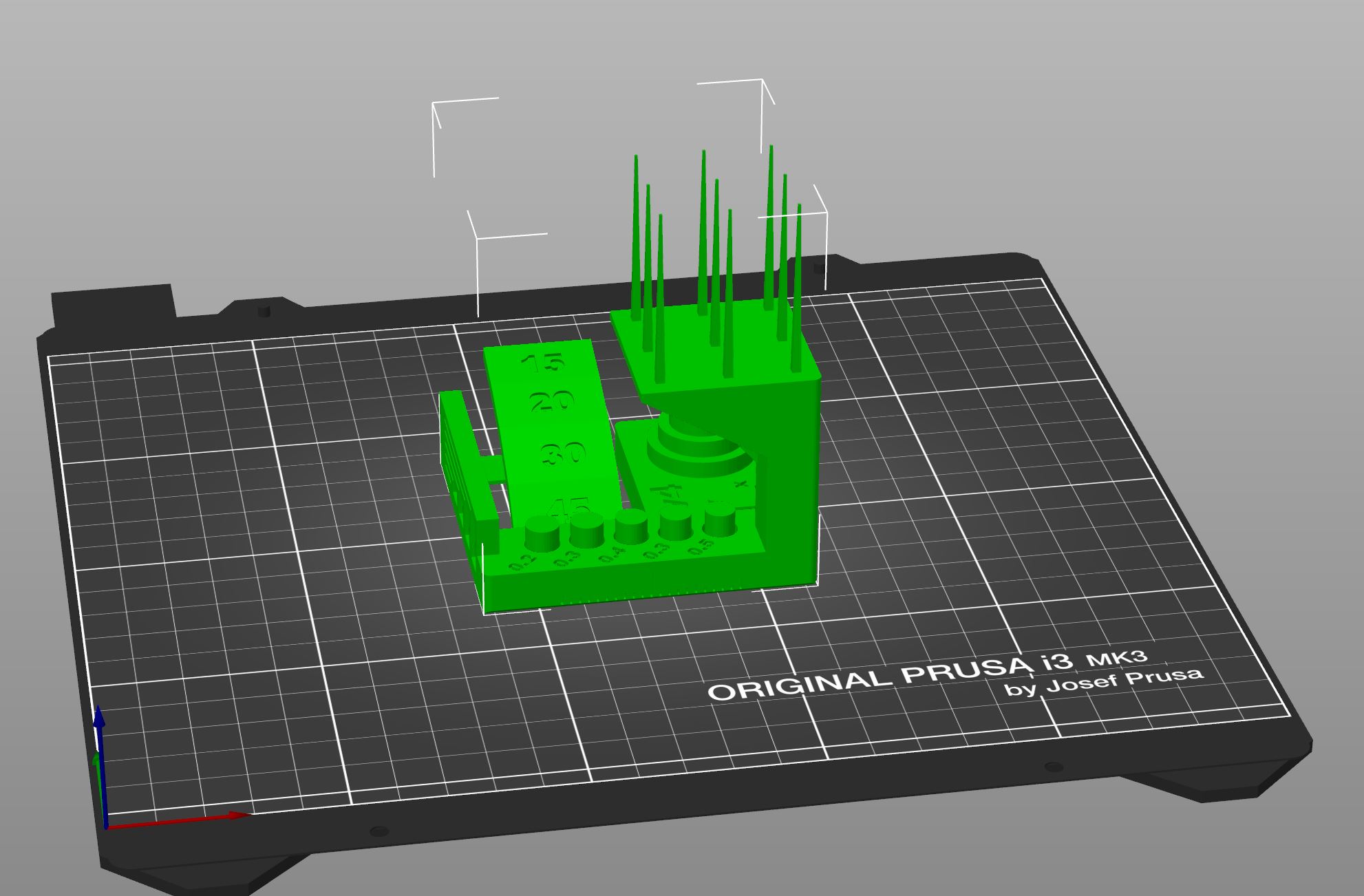
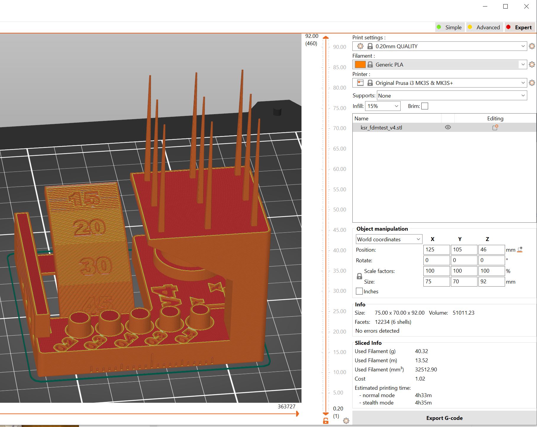
Per instruction on the repo I used “default” settings.
| Stress test file |
|---|
| ksr_fdmtest |
Now we must wait for the printer to be available.
After the printer became available, I started the print job. It took about 4 hours on 0.2mm layer height.
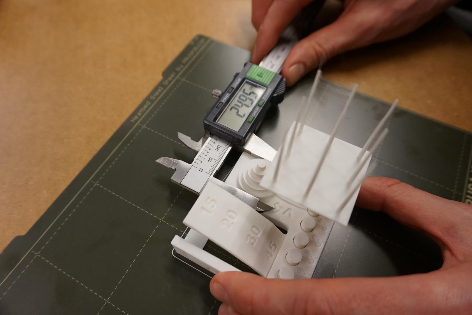
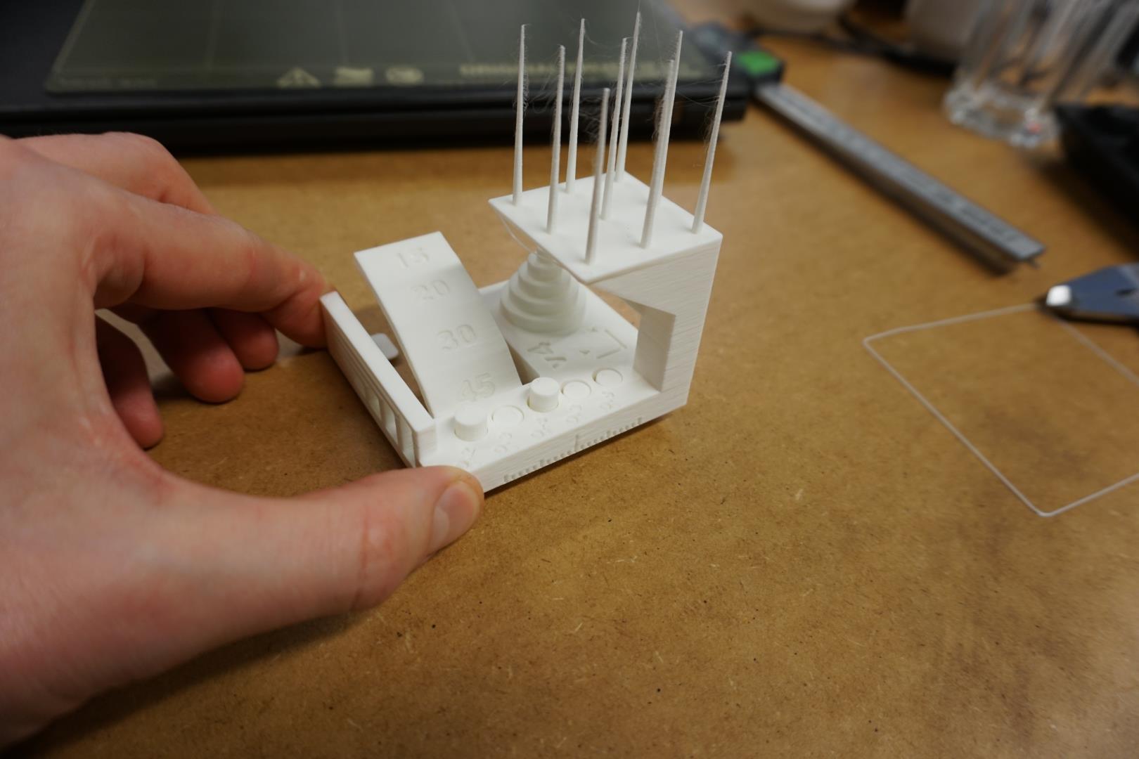
Taking the test as described on the site, I got the following results:
1. Dimensional Accuracy
| Target | Measured X | Measured Y | X Error | Y Error |
|---|---|---|---|---|
| 25mm | 24.95 | 24.96mm | 0.05mm | 0.04mm |
| 20mm | 20.00 | 19.89mm | 0.0mm | 0.11mm |
| 15mm | 14.99 | 14.93mm | 0.01mm | 0.07mm |
| 10mm | 9.96 | 9.99mm | 0.04mm | 0.01mm |
| 5mm | 4.99 | 4.93mm | 0.01mm | 0.07mm |
| Avg. Err: | 0.022mm | 0.06mm | ||
| Average of avg. X and avg. Y error | 0.041 | |||
| Difference between avg. X and avg. Y error | 0.038 |
This is top result, scoring a 5.
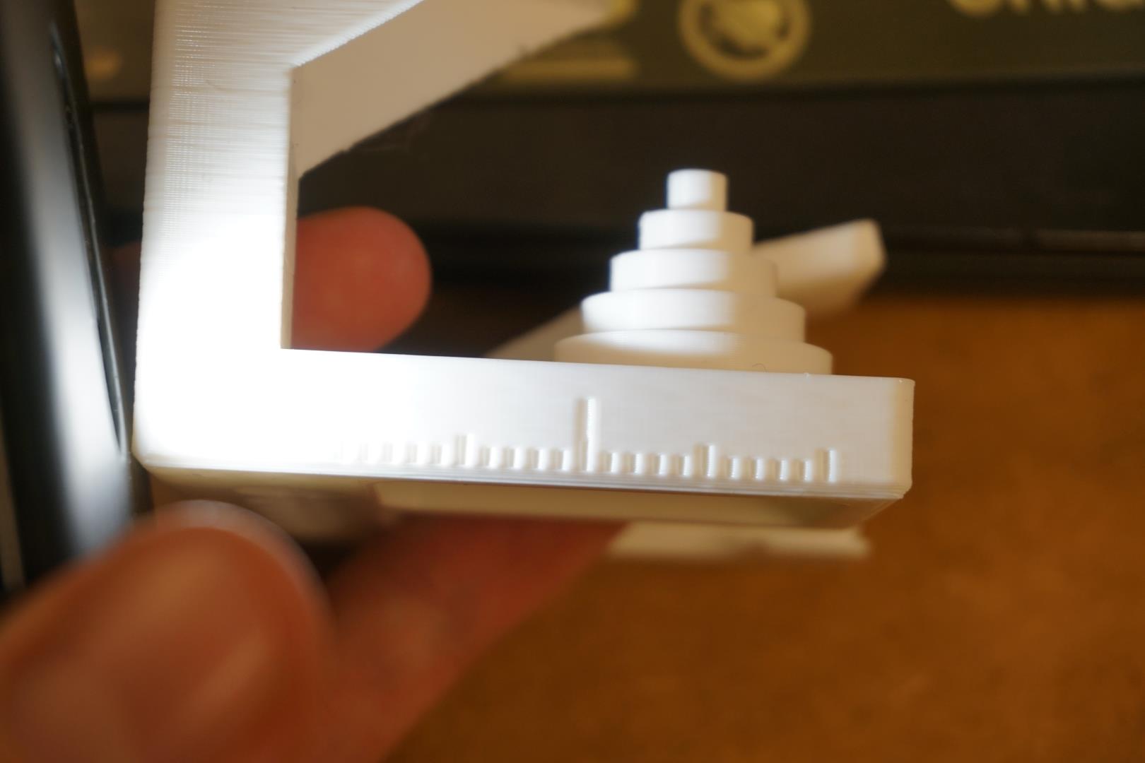
2. Fine Flow Control
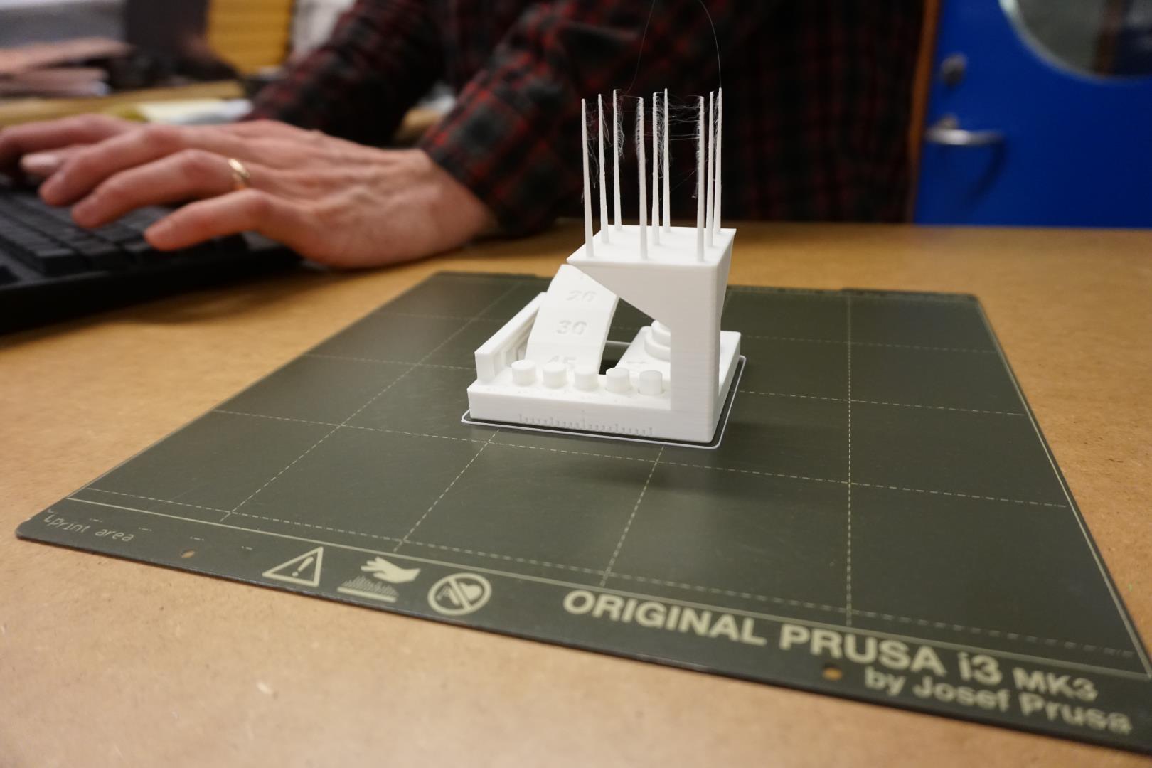
I actually broke a small piece of one the towers, but I noticed it was quite sturdy. It made a singing noise when I broke it and they are very well formed.
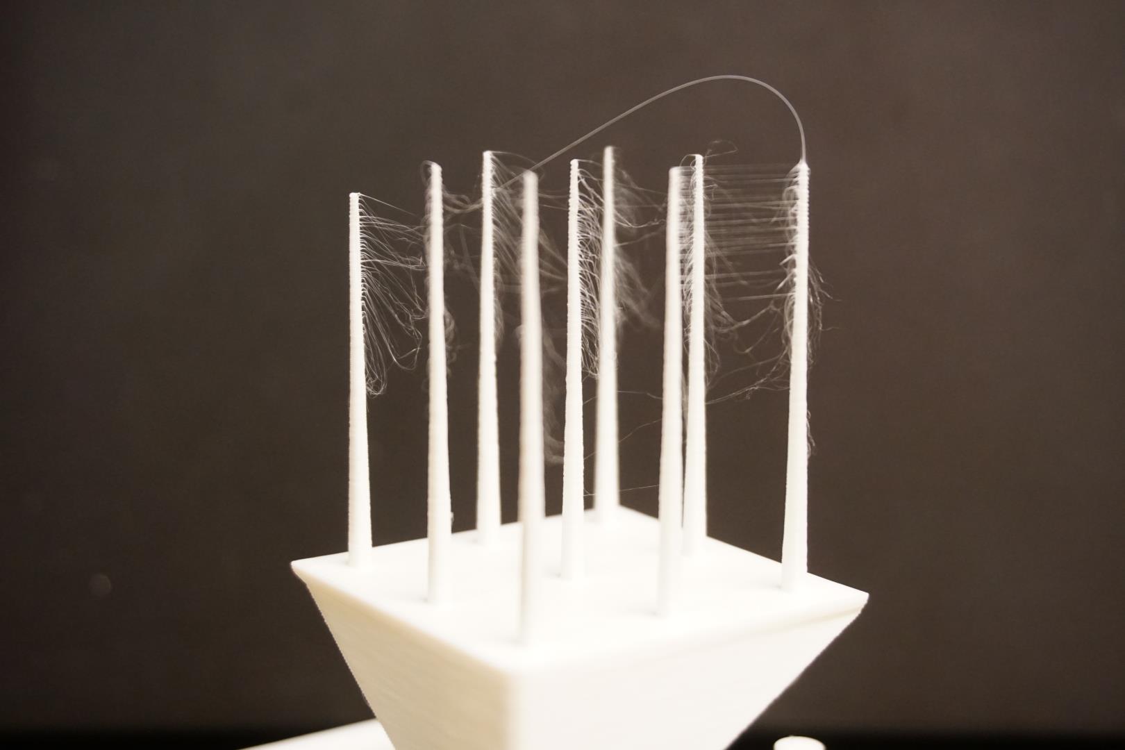
I inspected them and they are very uniform. The stringing is basically angel hair and basically disappears when you breath at it. But, stringing is stringing, so it a 2.5. (Giving this a 5 would really be fair also). Lets call it 3.75.
3. Fine Negative Features
Three of the pins simply fell out when removing the print from the plate. Fourth one popped out when barely touching it and the last one needed a slight pressure from one finger to remove. Brilliant!
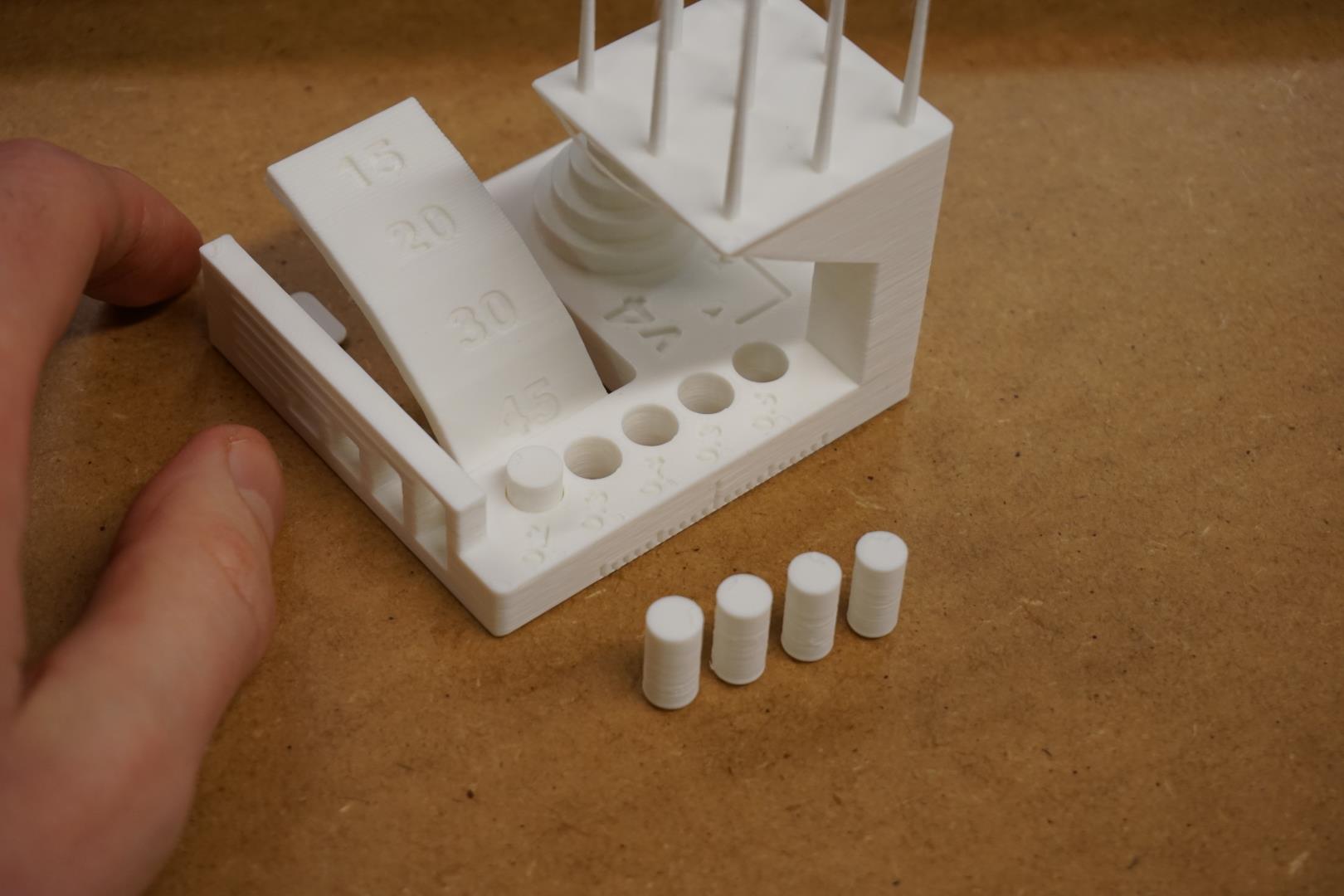
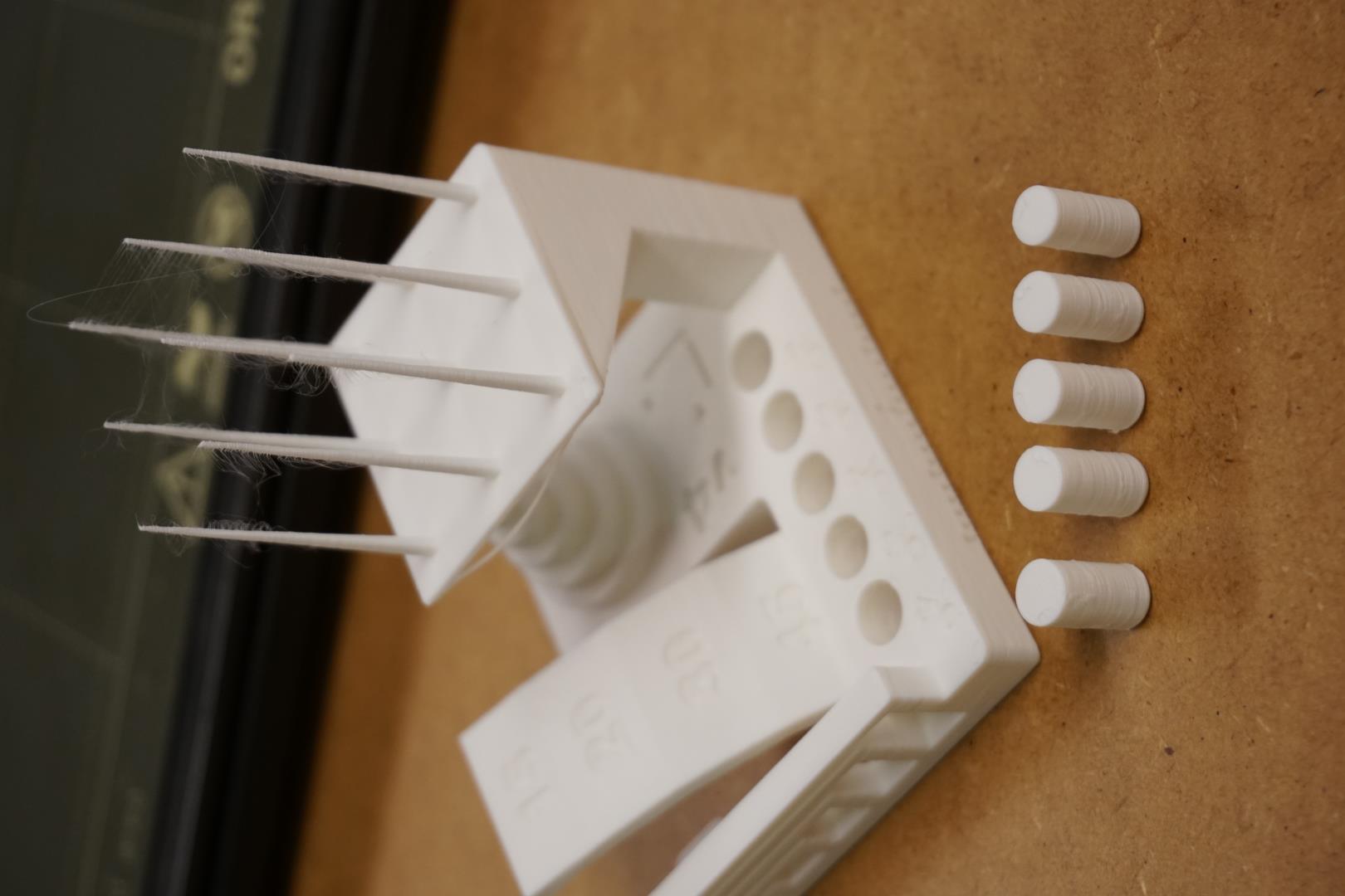
Thats a 5!
4. Overhangs
There is mainly a slight difference between the 15° overhang and the rest. If I had set the printer to a finer setting it probably would have been a bit more uniform.
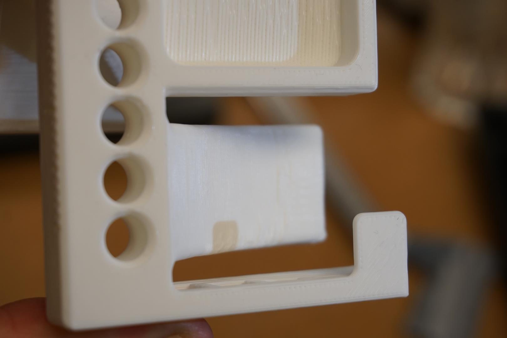
Thats a 4.
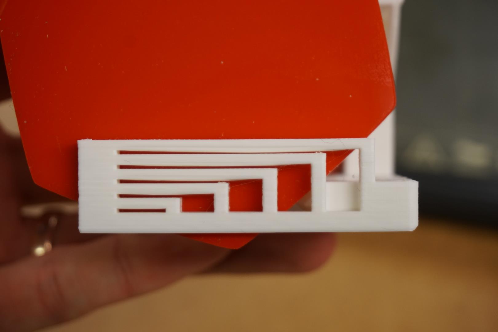
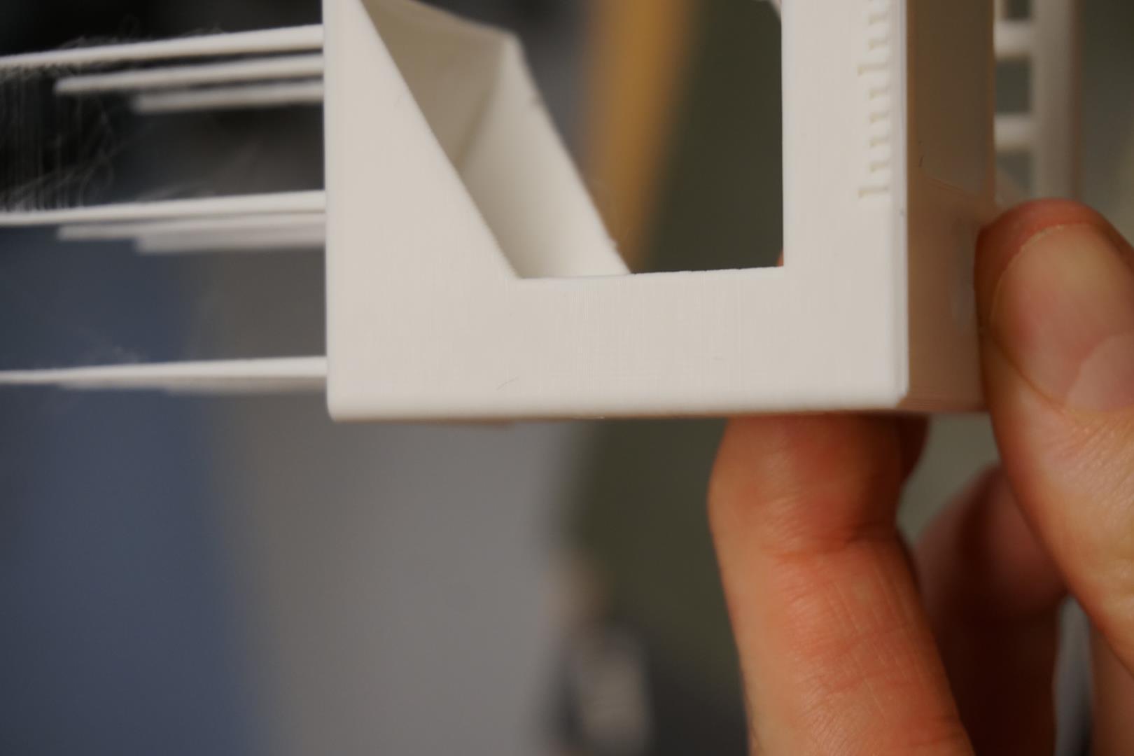
5. Bridging
The bridging was brilliant. No parts touch each other, scoring a 5. There is slight drooping on the longest ones though.
6. XY Resonance
There was no evidence of ringing in the print: 2.5
7. Z-axis alignment
The text is a bit unclear to me, but if I understand it correctly, the score is 2.5.
Test results
The total score is: (5+3.75+5+4+2.5+2.5) = 22.75
That’s on par with another Prusa result mentioned on the site. I’m very happy with the result.
Designing an additive only object
During the lecture I had an idea. Maracas!
I wanted to keep the design simple since time is limited and I may also try to work towards my final project during this week. I figured I’d start with a dodecahedron (took me a while to figure this word out) and just skip the grip/shaft.
I started poking around Fusion360 and Youtube but kind of found the ways I found a bit convoluted. So, I found a way to make use of the tools we used in Week 3.
I found this code to create a dodecahedron using OpenSCAD, included below:
module box(size) {
cube([2*size, 2*size, size], center = true);
}
module dodecahedron(size) {
dihedral = 116.565;
intersection(){
box(size);
intersection_for(i=[1:5]) {
rotate([dihedral, 0, 360 / 5 * i]) box(size);
}
}
}
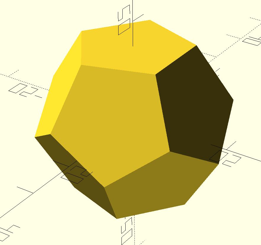
dodecahedron(20);
Running it resulted in this nice dodecahedron!
Next I wanted to export this to Fusion360 to do some further work the model. I tried using .stl and .3mf filetypes but these imported as a mesh which I had trouble converting to solid body in Fusion.
I found this thread and followed that path. I exported again, this time to .CSG.
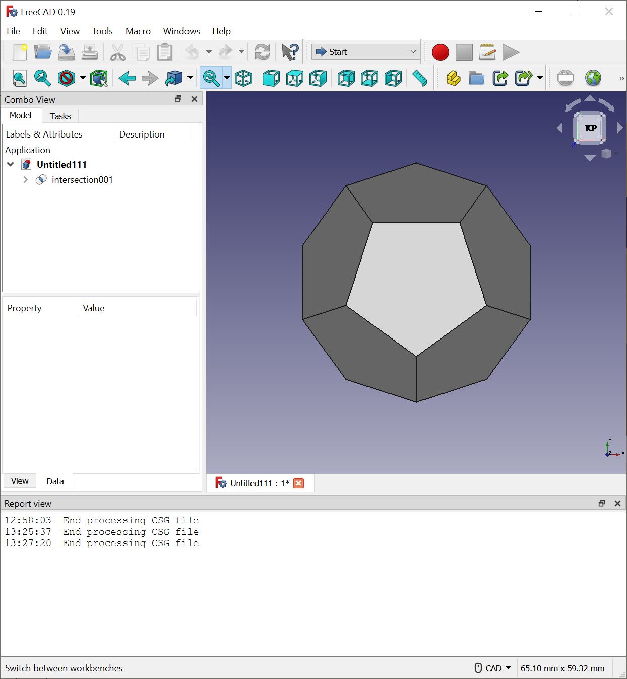
That file I opened in FreeCAD and exported as STEP.
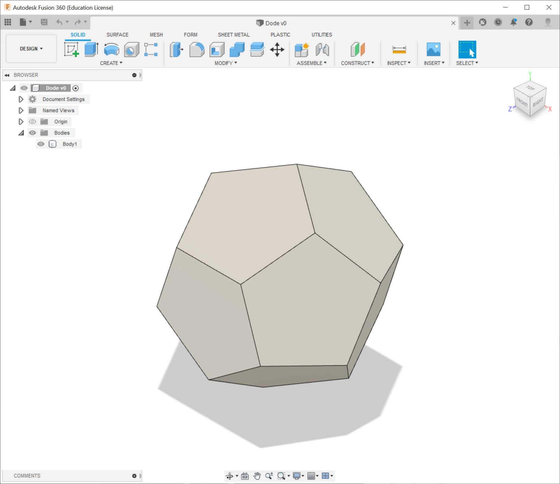
Once I opened that in Fusion, I had this nice solid body!
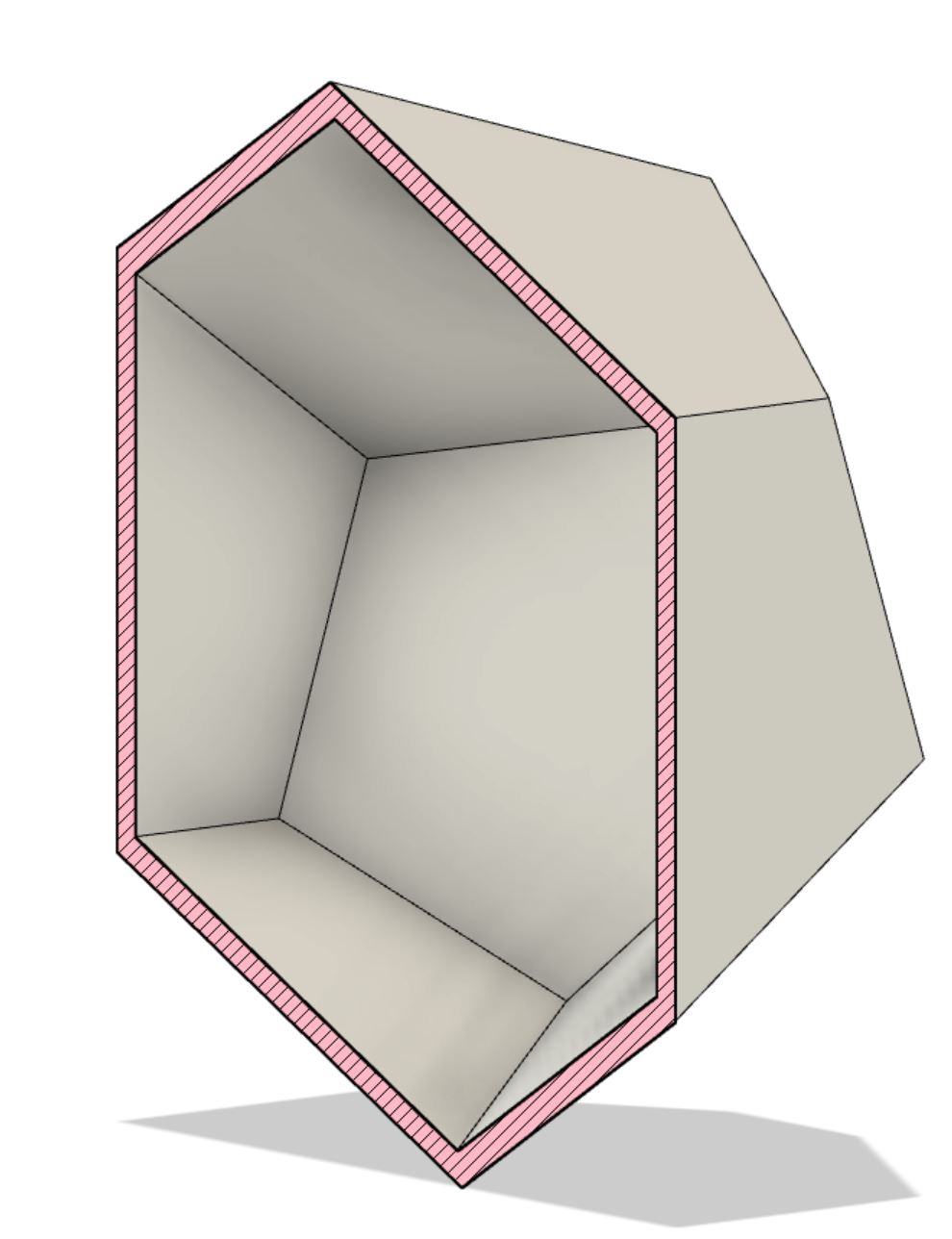
Using the shell command, I hollowed out the body and set the wall width to 2mm.
I then added section analysis to the body and verified the result.
For this simple version, I wanted to utilize a property within Prusa slicer, which is to add a pause to the print. So I’ll simply add a pause mid-print, add rice or other material for making noise, and then resume printing!
You add the pause by right clicking the layer-viewer-arrow-plus-thing.
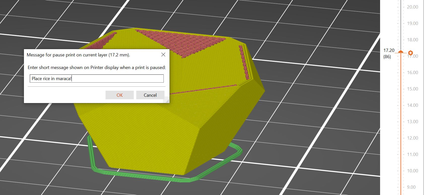
This option is extremely handy, for example to make a bearing, adding nuts or magnets to a project.
You pause the print at specific layer height and add the parts and continue.
| Simple - dodecahedron files |
|---|
| CSG |
| SCAD |
| STEP |
| STL |
| gcode |
| Fusion360 |
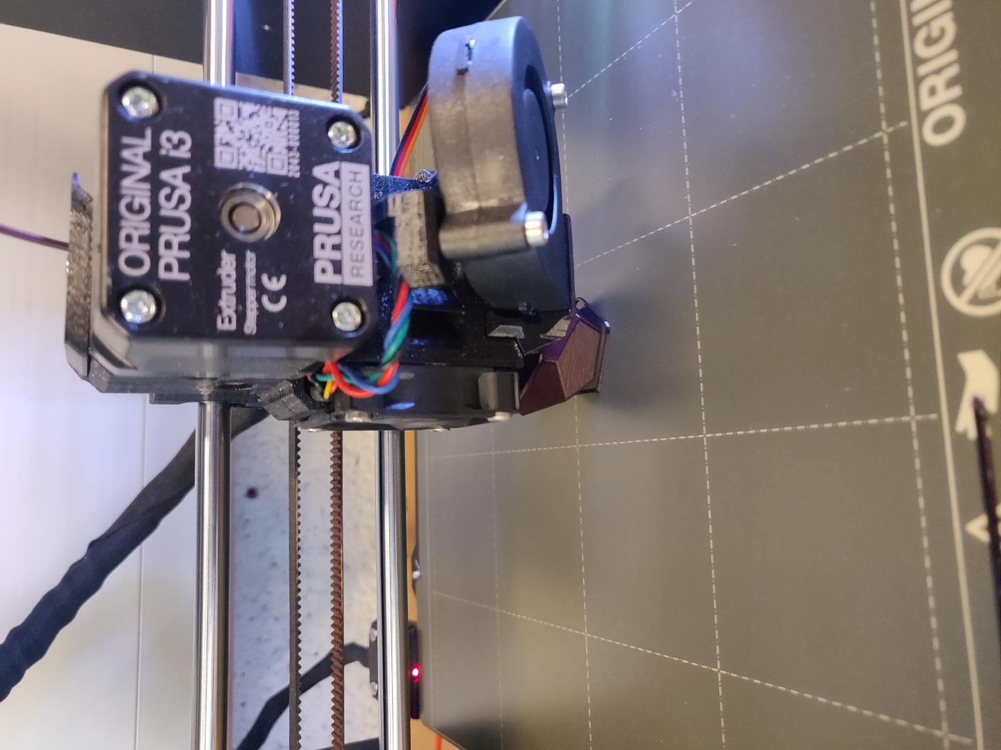
Printing the dodecahedron
Next up, printing the little shaker. I’m so lucky that next door to the Fab Lab is the culinary department of the school, so getting some rice is no problem.
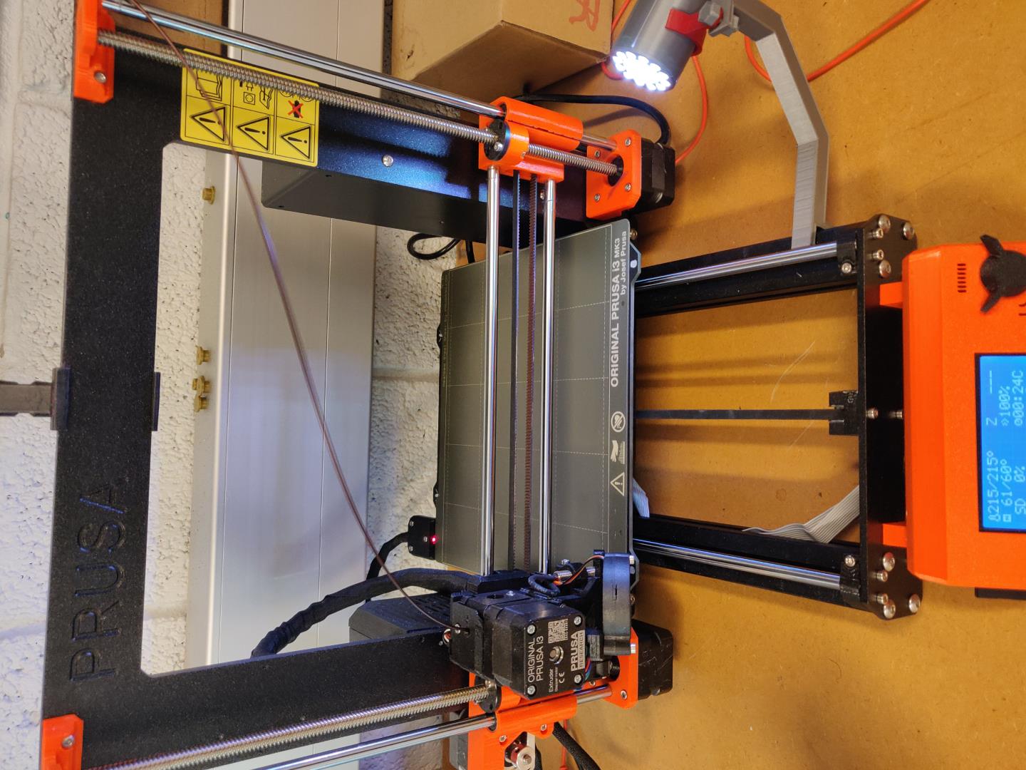
I load the gcode to the printer and start printing.
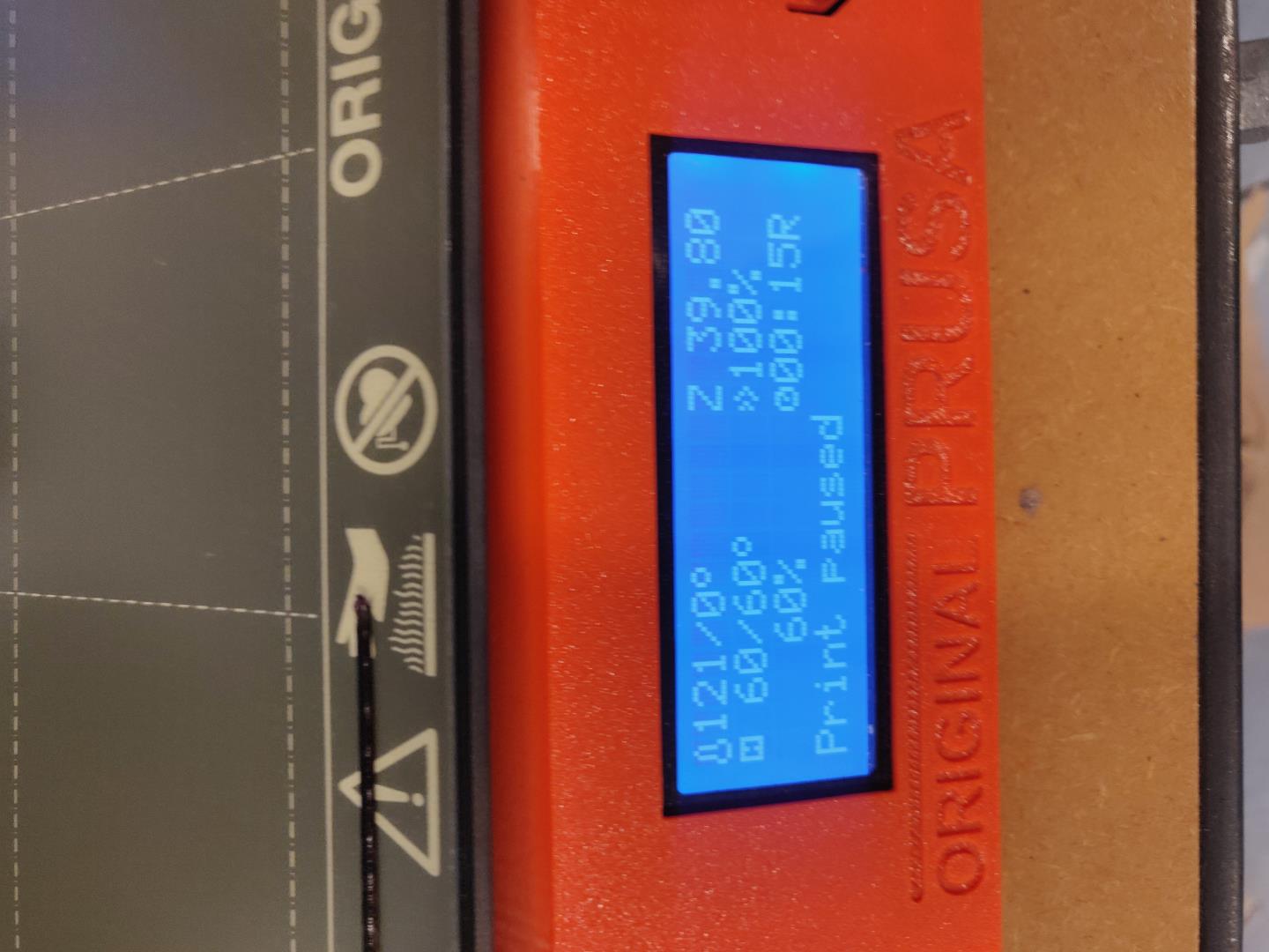
After about 25 minutes, the printer notifies that me there is a pause. It moves the print head away from the object and waits.
I add rice and resume printing.
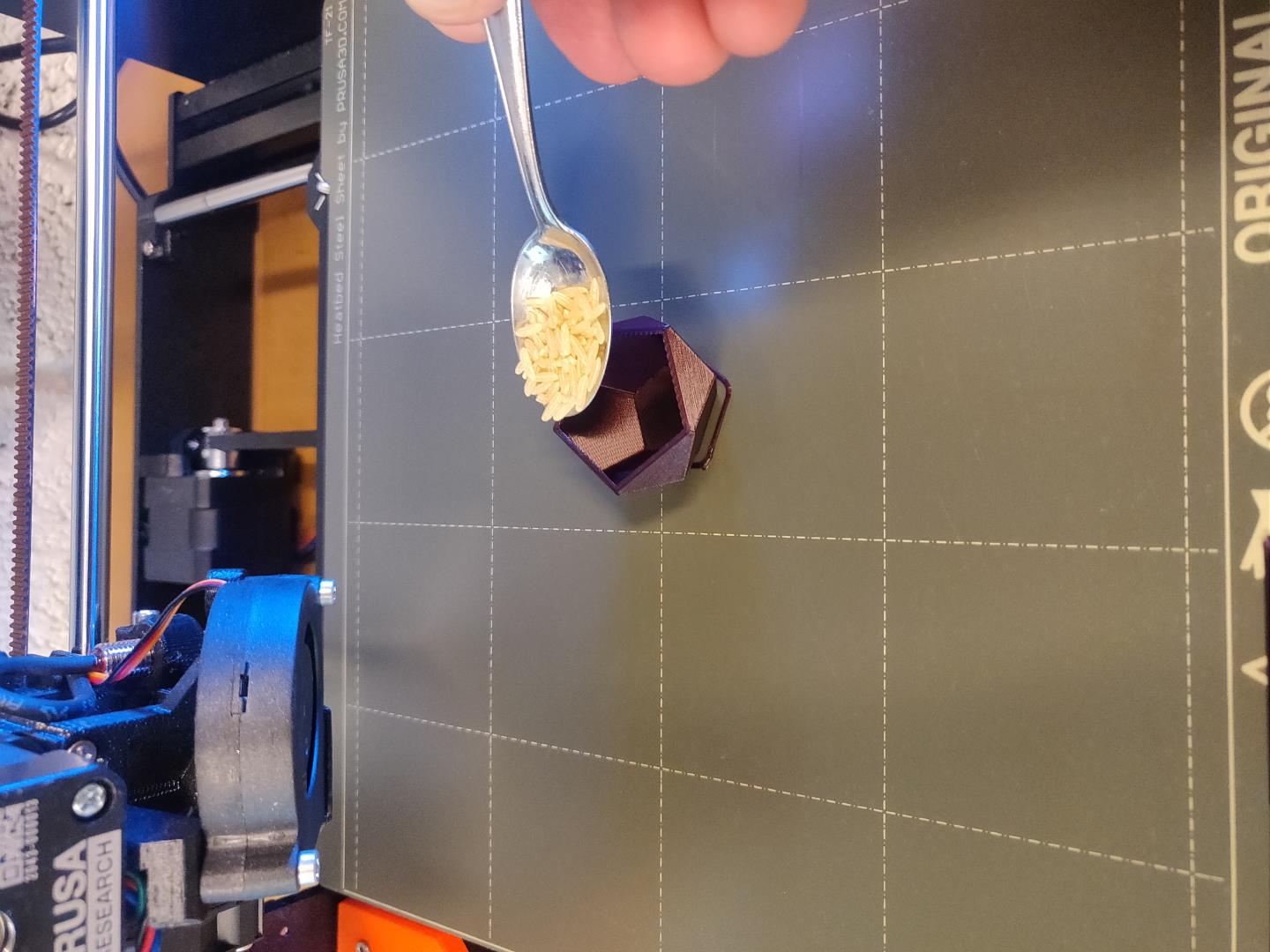
It resumes the progress without a hitch!
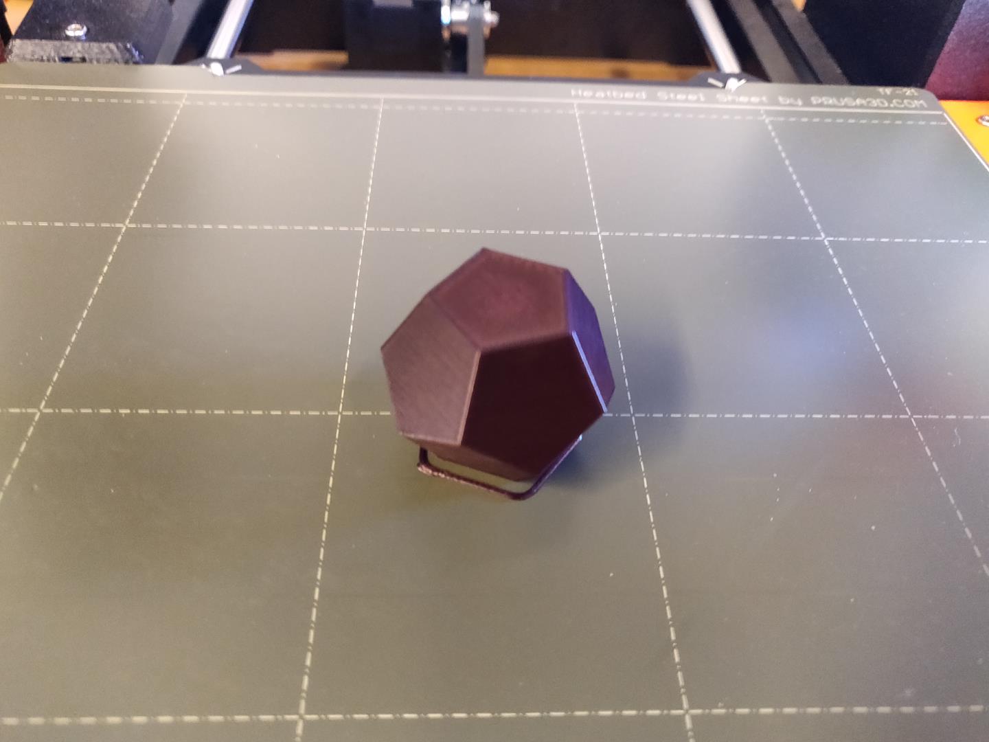
And the money shot is here:
| Compression | ||
|---|---|---|
| Original | After | Reduction |
13.16MB |
717.77KB |
-94.68% |
Thanks videosmaller!
OpenSCAD revisited
My brilliant instructor noted that maybe I should have explored OpenSCAD a bit more, with the aim of shortening the toolchain. Well, that makes sense. Creating the “shelled” Dodecahedron within OpenSCAD was a breeze! I just used the difference function and crated two objects, one larger and one smaller. This then hollowed out the larger object.
Then it’s as simple as 1,2,3 to get an .stl object. Well actually its F5(preview), F6(render), F7(export)! F8 is direct to print, if you are setup for that!
Brilliant!
module box(size) {
    cube([2*size, 2*size, size], center = true);
}

module dodecahedron(size) {
      dihedral = 116.565;
      intersection(){
            box(size);
            intersection_for(i=[1:5])  {
                rotate([dihedral, 0, 360 / 5 * i])  box(size);
           }
      }
}

difference(){
    dodecahedron(22);
    dodecahedron(21);
}
Actually designing an additive only object
Turns out I did not actually design anything, so let’s give it another shot!
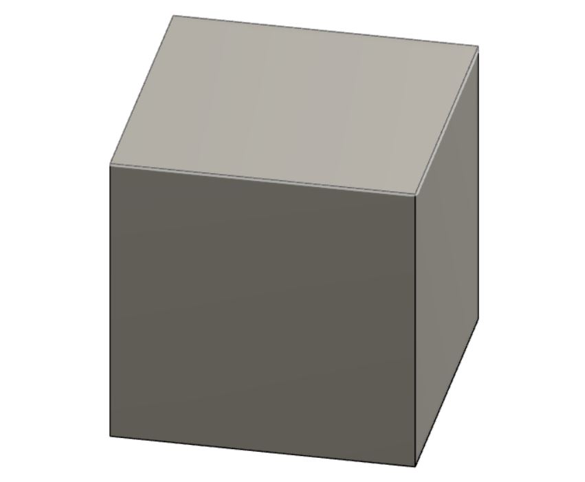
How would you mill a sphere from within a cube? I have no idea! But with 3D printing, no problem!
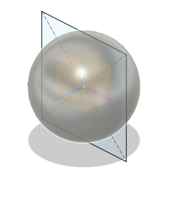
Let’s start with a simple cube. I take care to extract it in two ways, so the origin point of the sketch is the middle. This comes in handy in a moment.
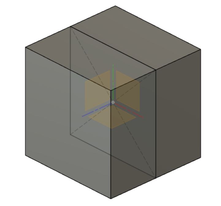
Next, from the origin point we create a sphere. The cube body is hidden during this step.
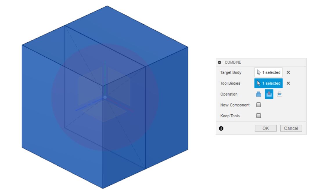
Then we use the “Combine” function to cut the sphere from the cube. Notice the “Keep Tool” option in the dialog. If it’s not selected, the part that’s used to remove from the other (the tool), is discarded. Sometimes that is OK, other times it’s not so good. Please take this into consideration.
Next, just to verify that it’s actually hollow, we use the section analysis to take a peek
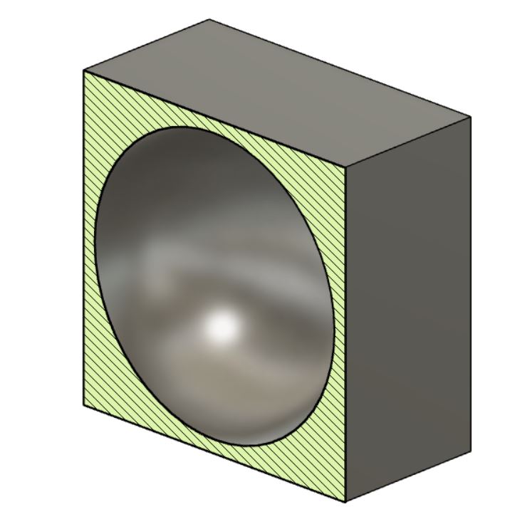
Good luck making this from a solid object on a lathe!
| Design file |
|---|
| Fusion360 |
3D Scanning
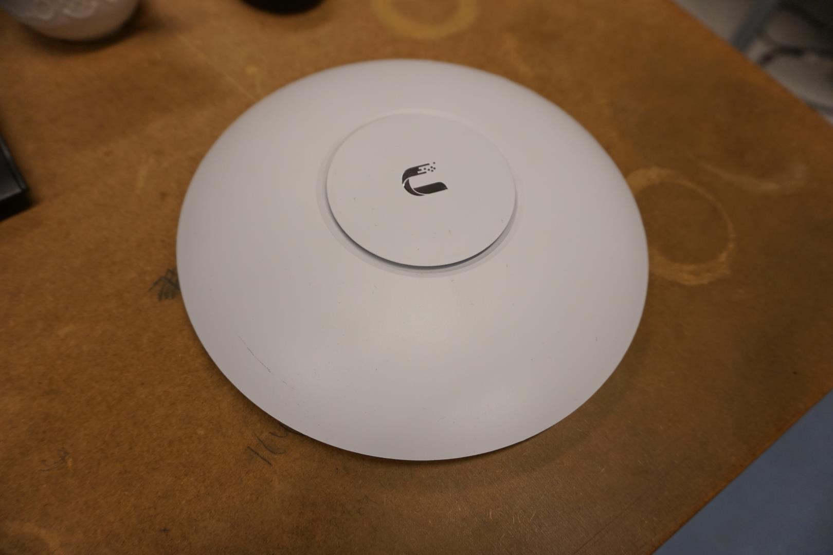
As mentioned on another part of this site, my work is split 50/50 with the Fab Lab and the schools IT service. One of things I needed to get was a new WiFi access point mount. So, instead of ordering stuff online and scanning something just for the sake of it, I decided to squish two flies with one punch and do something useful.
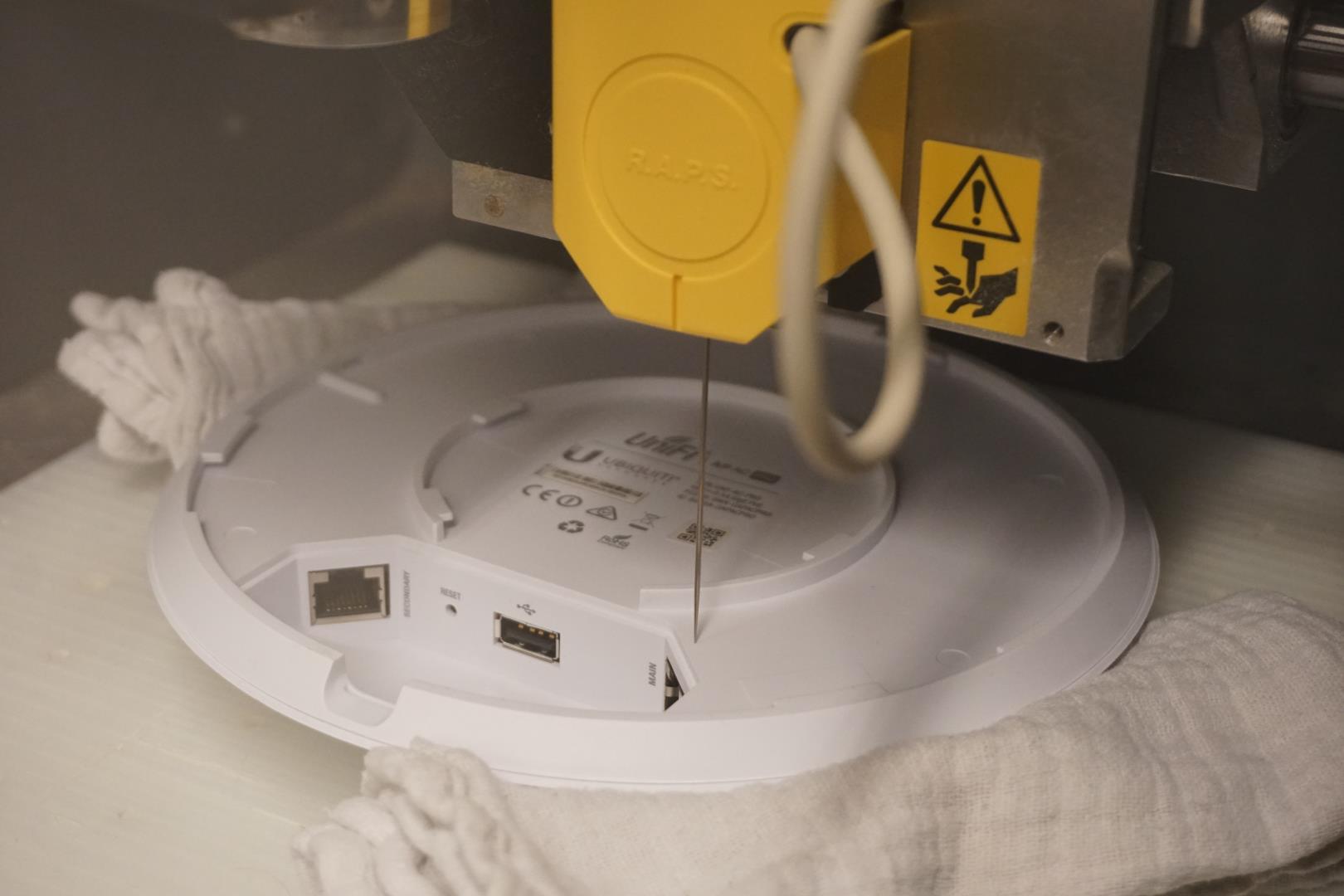
Here I used our Roland MDX40A with the 3D scanning needle attachment.
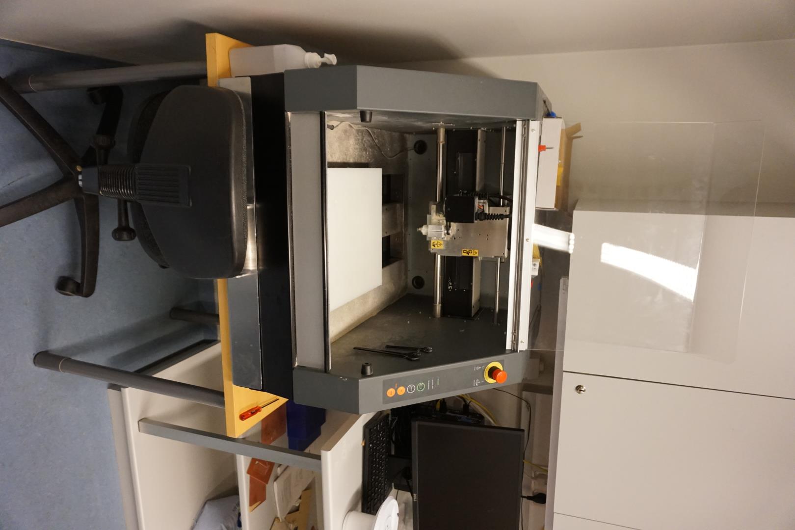
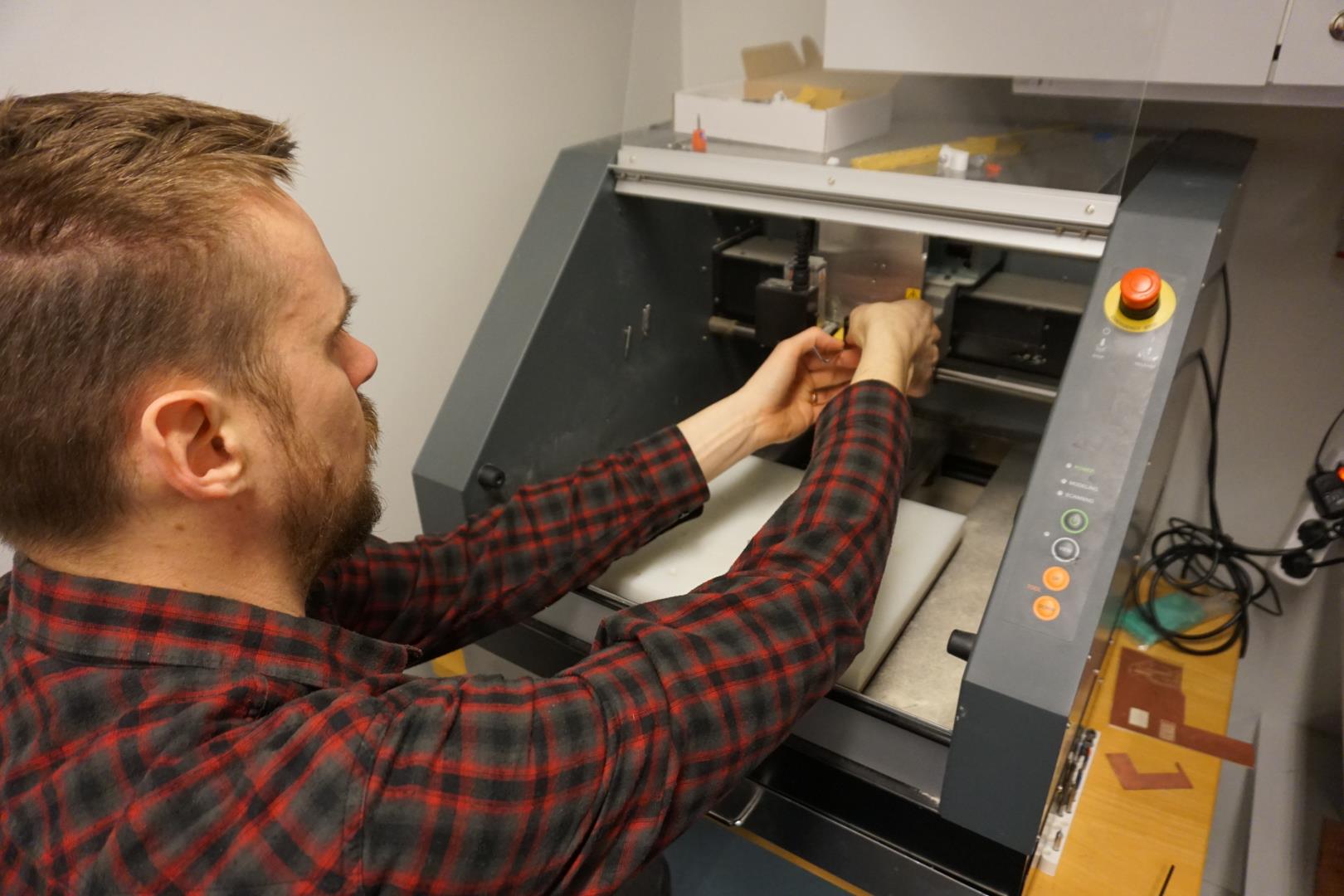
To be able to scan, you need to remove the spindle and attach the scan needle head.
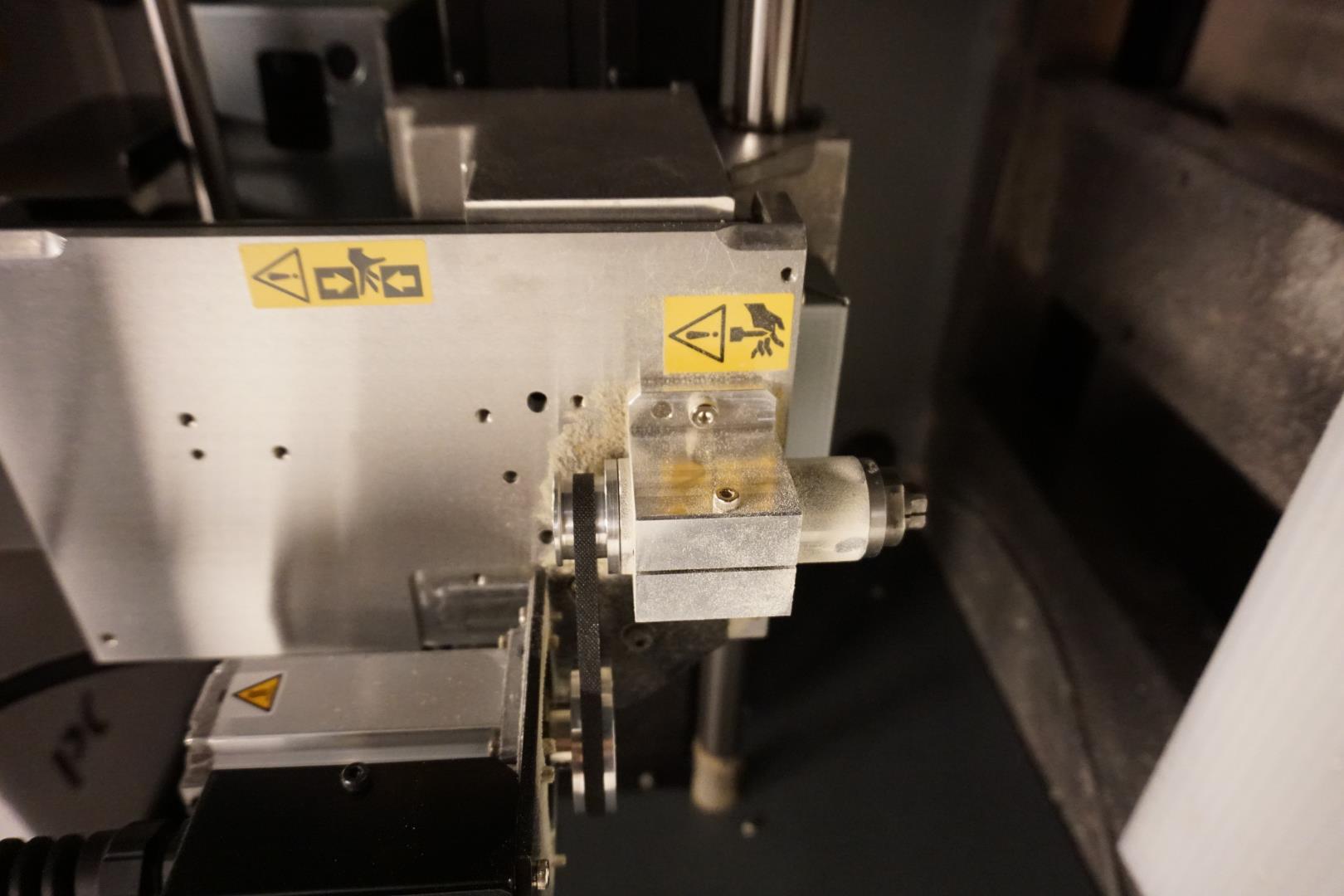
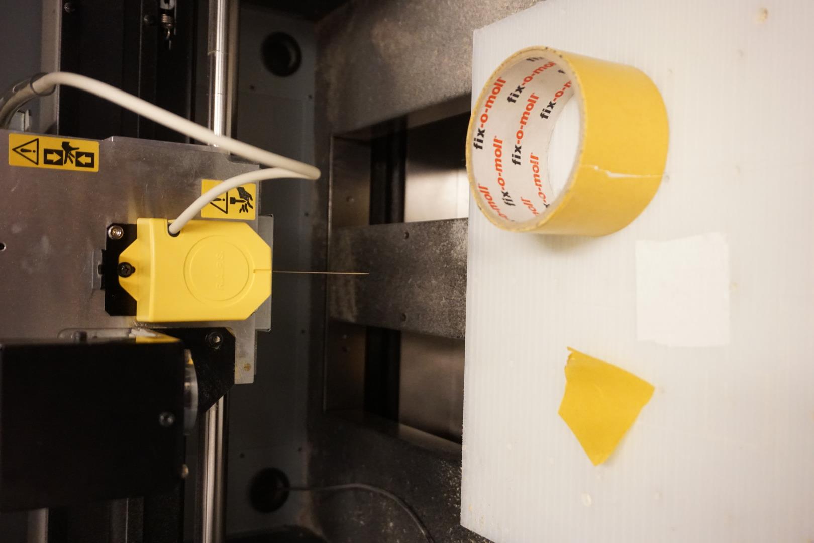
It is held by two screws and is easy to remove. The scan head is then attached. Care needs to be taken not to damage the component. It comes with a protected plate that is recommended to keep on during attachment. You also need to connect wiring from the needle head to the machine.
We used a bit of double tape to get the access point to adhere to the bed and stuffed some rags around it for support.
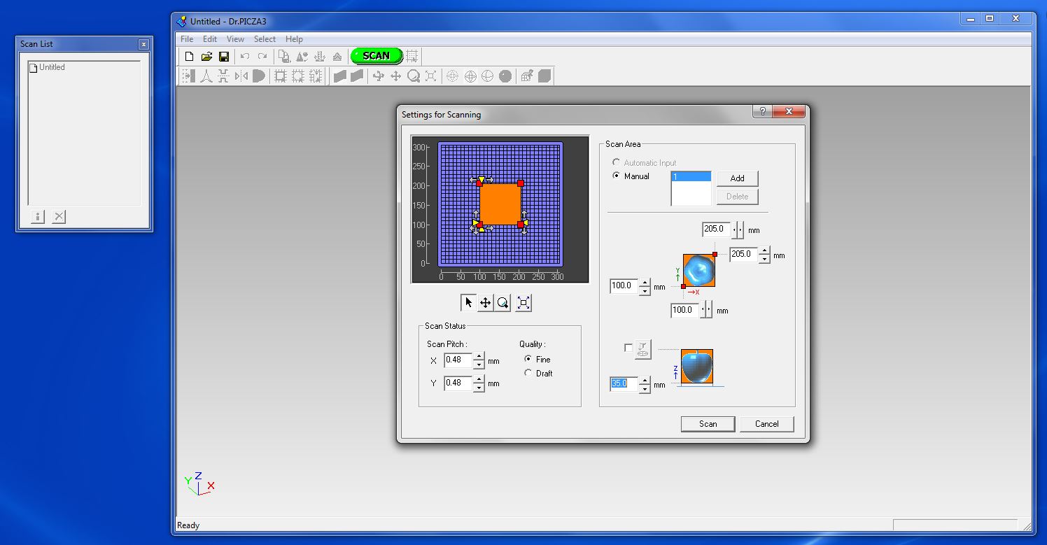
Next I set up the program. To save time we set the scan area and center it on the specific part of the object we want to scan. This is pretty straight forward, but I had to start again because I failed to notice the little box to tick in the lower middle part. That engaged the Z axis zeroing.
This takes a while! But after a bit, we see a 3D model start to form.
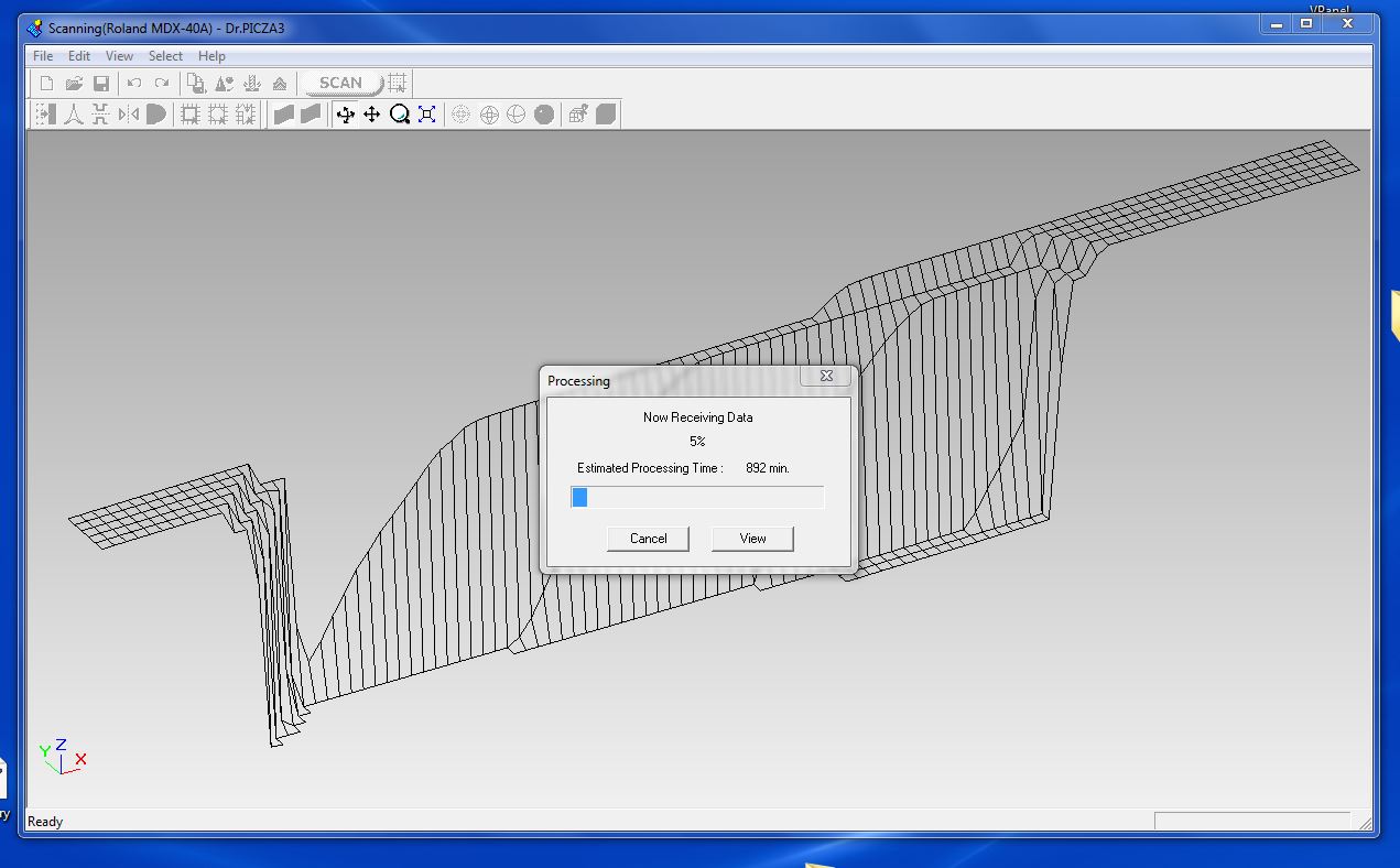
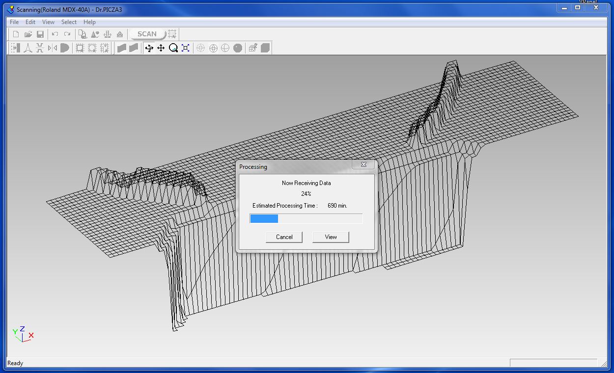
Now, lets leave this to do it’s scanning and call it a day!
Fast-forward over the weekend
Covid!
It’s official! I have COVID-19. The entire family has been feeling sick the last couple of weeks and now it’s my turn to get the virus officially.
Anyways, moving on!
After the weekend, I asked my dear colleague to retrieve the data from the scan send it to me, which he did promptly.
Opening the .stl file in Meshmixer, I see that it turned out rather nice.
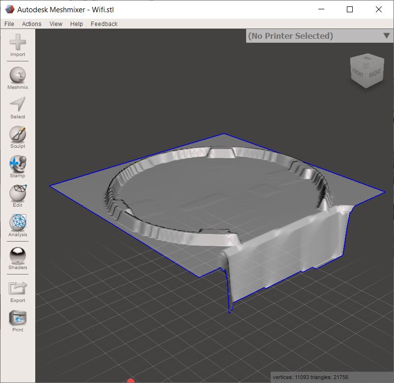
To clean the mesh up, I use Edit and the Plane cut feature. I select the flat part of the mesh and cut it off. Next I aligned the remaining object to the ‘ground’.
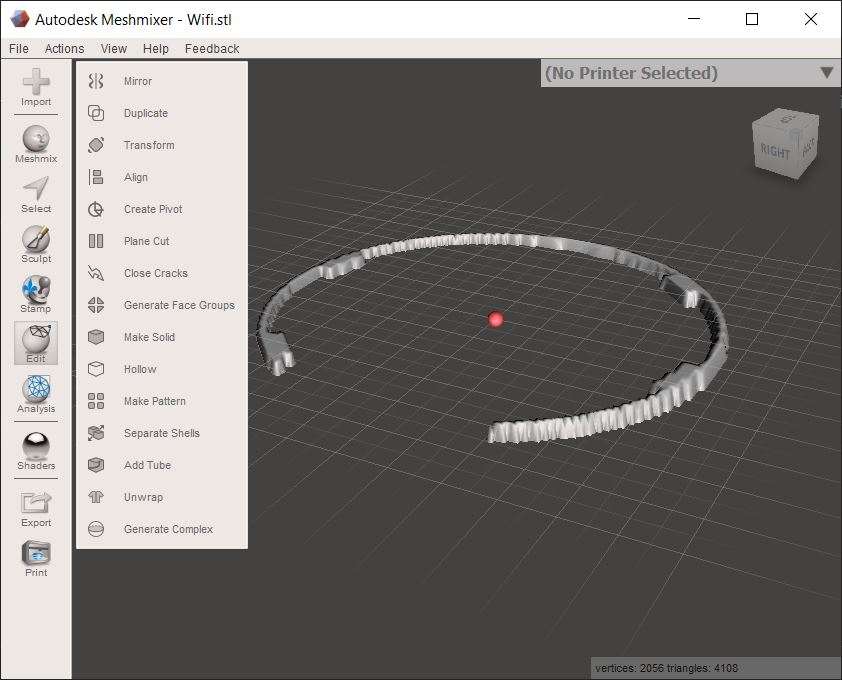
2.5D vs 3D
Now, I must mention that this is not really 3D scanning, it’s 2.5D scanning. Since the needle scanner only scans from the top, it misses all features that are below another surface. The fixture on the WiFi access point has these little tabs that secure it to the mount when you turn it. These show up as solid blocks in the mesh.
As we can see on the picture above, the model is pretty jaggered. So, based on the amount of time and effort spent on this type of scanning, I personally would pursue other ways of modeling what is needed, at least in this case.
But we do see the necessary features of the mount needed and could, create the wall/ceiling mount with this model in hand.
| Scan files |
|---|
| Scan .obj |
| STL file |