Final Project
This is is kind of a build log, written in different times during the class. It may contain invalid information regarding the final outcome.
Project plan
At the beginning, I found the idea of using the weekly assignments to build parts for the final project to be really attractive. I made sure to catch as many of Neil’s live lectures as possible, as also the recitations. Each week my instructor and I would speak, plan and go over the status.
In reality, I did not find it completely possible to use each week to build directly towards towards, though each week added to the much needed skills. Important weeks were the cnc milling, electronic design and production along with embedded programming. These produced boards that functioned as a base for my project.
Early meetings and discussions with my instructor made the idea of the final project rather clear from the start although I kind of waited until after networking and communications week to properly implement the solution.
So in hindsight, the planning was perfect as these step show:
- First weeks of Academy, get acquainted with the Fab Academy and settle into my own workflow.
- Decide on the final project (documented below)
- Study the Academy, gather knowledge to work with confidence.
- Finish the project in time for summer road trips!
Inspiration of final project
From an early age, a couple of my main interests have been computers and cars. Now that I have a family too, which takes precedence over most hobbies, I must find creative ways to mix hobbies and interests with my family.
So I wanted to make my final project involve:
-
My family, with emphasis on children
-
An automobile
-
A toy device with digital interfaces
The pitch
Why buy an ipad for hundreds of thousands of Icelandic krónur (ISK) to prove mindless entertainment when you can make your own digital activity-board for car-rides with a child?
The idea
The idea is to mount two units in a vehicle, one parental unit and one child unit.
The child unit should include some input and output devices, for example LEDs, a display, microphone, switches and/or similar.
The parental unit should include some input and output device, such as a child-loudness-meter.
Right now the exact inputs/outputs are not decided but current ideas include:
- LEDs
- A small display
- G-force/Gyro/Motion sensor
- Microphone
- Buttons/switches (might be hard to reach for child?)
- Illumination from the child unit
- Play sounds
- Play game with co-driver (if possible)
- Shared control over some led/items via communication
Parental unit
The parental unit is to mounted on the dash, in reach for both driver and co-driver.
Functions
- Display loudness of child
- Control LEDs on child unit
- …
- ???
- profit!
Components
| Component | Description |
|---|---|
| LEDs | For interactive fun |
| Display | For visual feedback of child loudness |
| Buttons/switches | For LEDs and more |
Child unit
The child unit is mounted on the back of a front seat. It should be reachable/viewable by the child.
It must not have extremely hard/sharp components on the outside or cause immediate danger to the child in case of a traffic mishap.
Functions
- Display graphically movements/shakes/motion of the vehicle
- Play sounds?
- Play (simple) game with parental unit?
- …
- ???
- profit!
Components
| Component | Description |
|---|---|
| LEDs | For interactive fun |
| Display | Visualize motion of vehicle |
| Microphone | Microphone to record loudness |
| Speaker | Play sounds |
| Buttons/switches | Buttons/switches on the child unit |
Communications
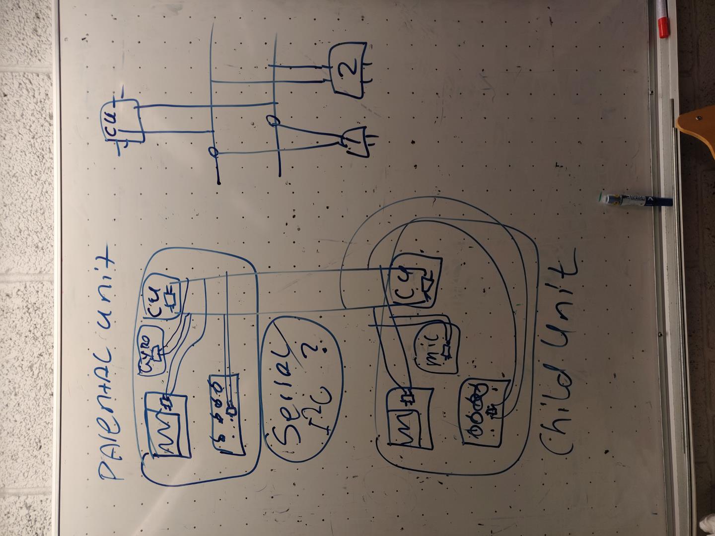
My current thinking is that I have multiple boards, each with their specific purpose. Such as a screen board, a microphone board, a led and button board, etc. Each of them communicate through a protocol such as I2C or Serial.
I’m hoping to get a clearer idea of this during the networking and communications week.
Design considerations
I plan to make a pair of devices, one parental unit and one child unit. It would make sense though to have it set up so that adding more child units is easy. I have two children!
This is something I must research and keep in mind. It would be a very nice feature.
I2c may be an option?
Progression
Note: This is a live document and the timeline might confuse mere mortals.
Child unit
It’s now time to start doing some work on the final project. I start with the child unit, since if life/project spirals out of hand, I can at least hopefully create entertainment for the backseat dwellers and leave out the parental unit or the connectivity between them.
A quick session in Fusion resulted in this. I will be revisiting this in soon, since I have not yet decided on the final design. This drawing is without parameters and is basically just a placeholder.
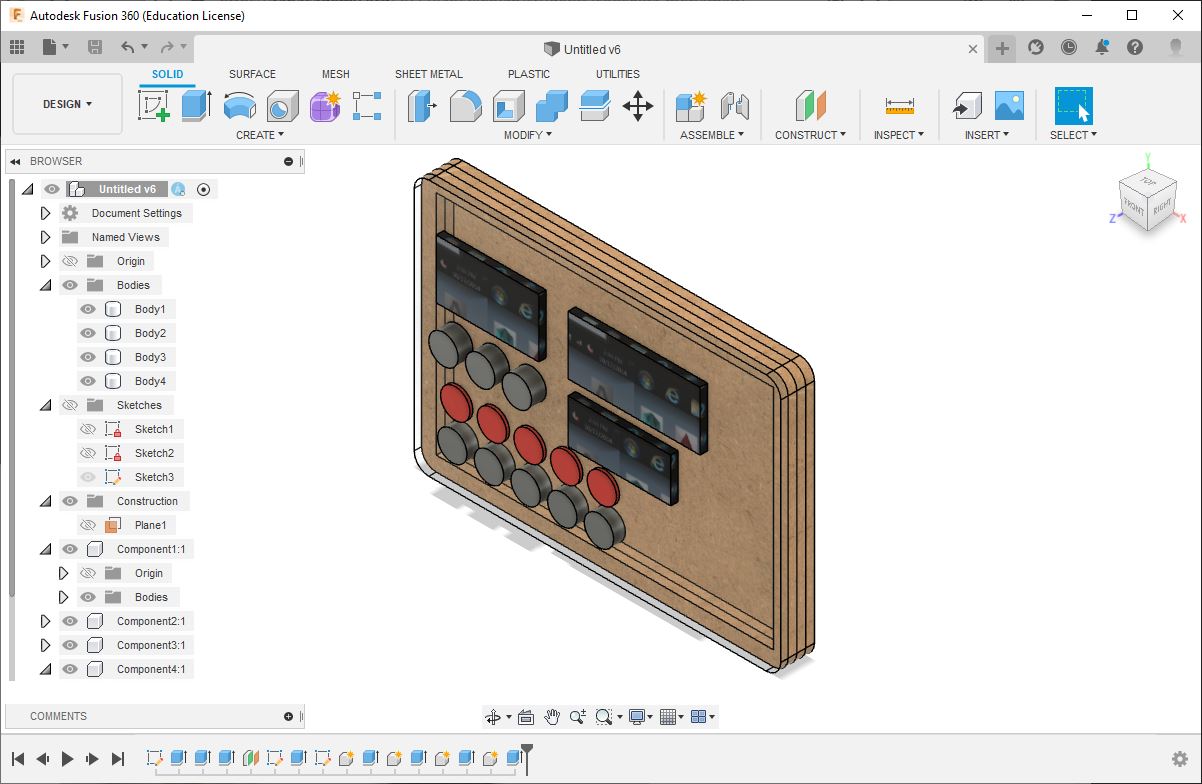
Here it is shown with some screens, buttons and LEDs.
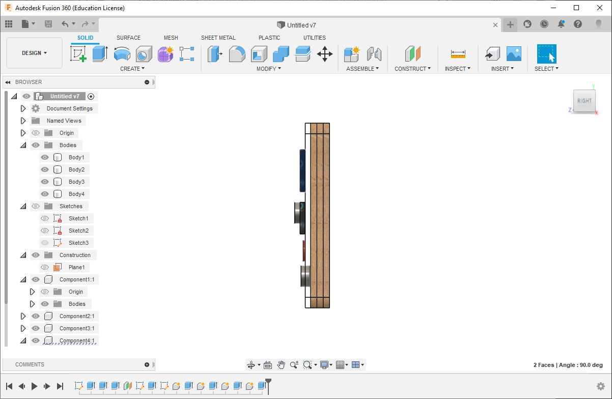
From the side, I’m showing the construction. The idea is to use a clear front panel, to show wiring and boards below, but use wood/MDF for the raiser and back panel. The raisers are meant to create space for wiring and boards.
This I hope would inspire interest in the inner workings of things!
Front mount
During a bit of downtime/caffeine-hyper-activity, and the fact I took my car to work instead of my bike, I eye-balled the measurements needed to mount something to the central console of the family grand-tourer.
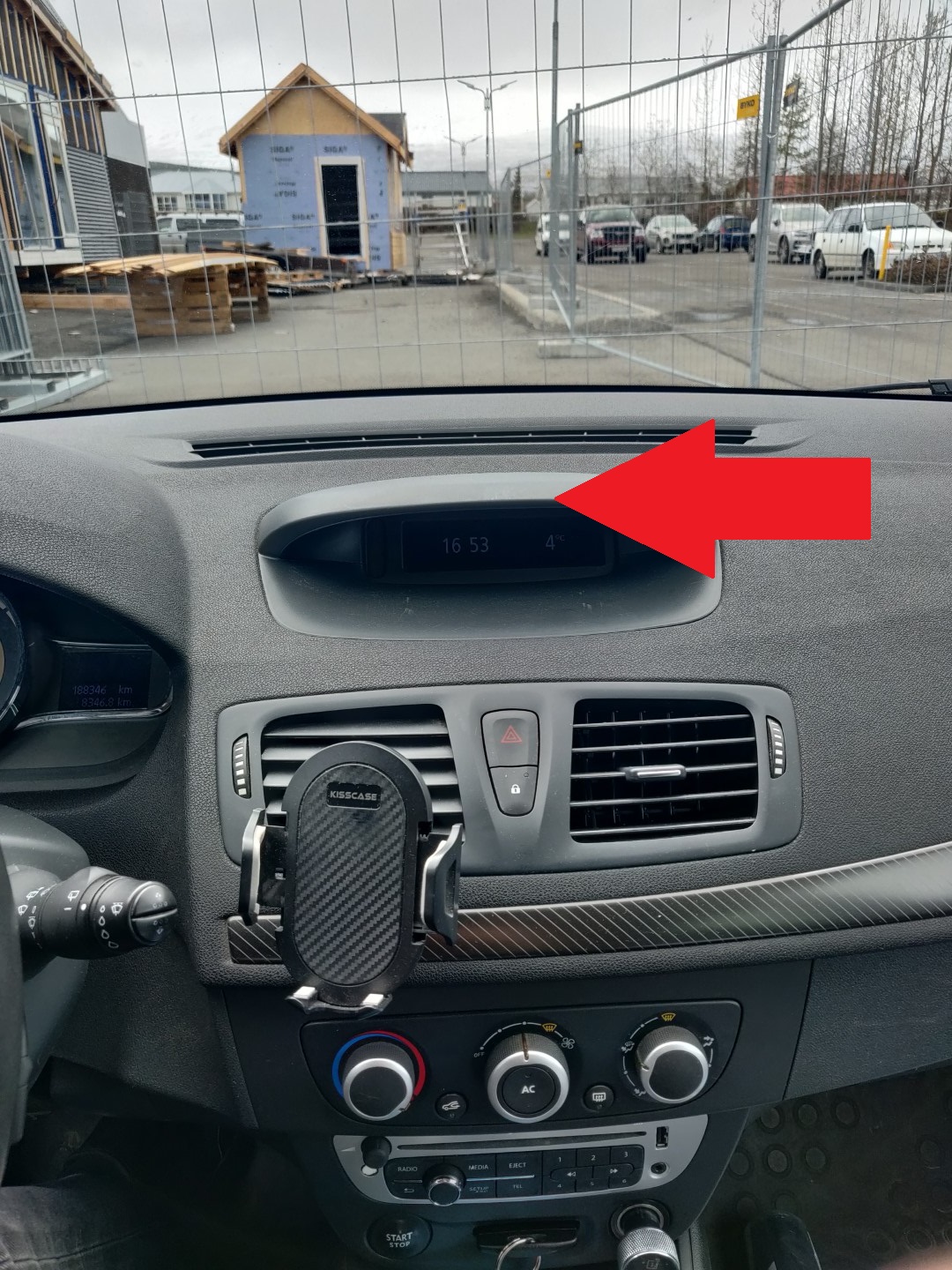
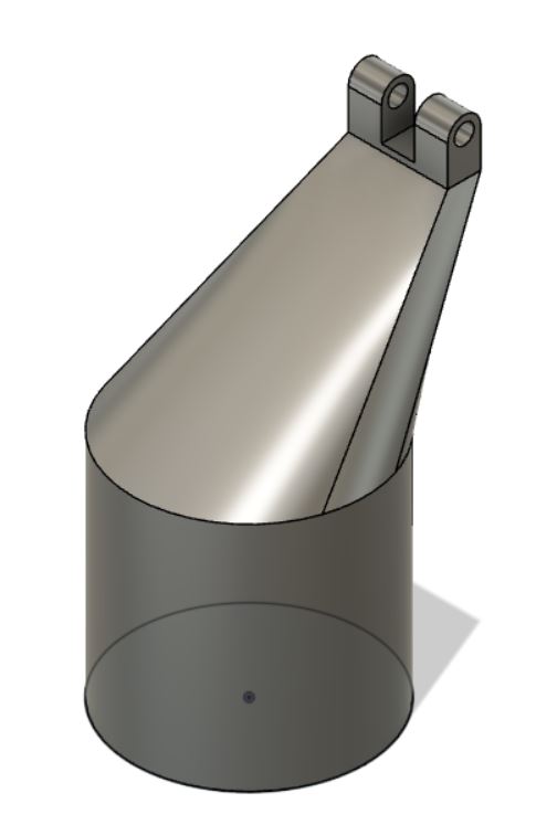
I started sketching something up in Fusion 360 and soon had a semi-nice object in digital form.
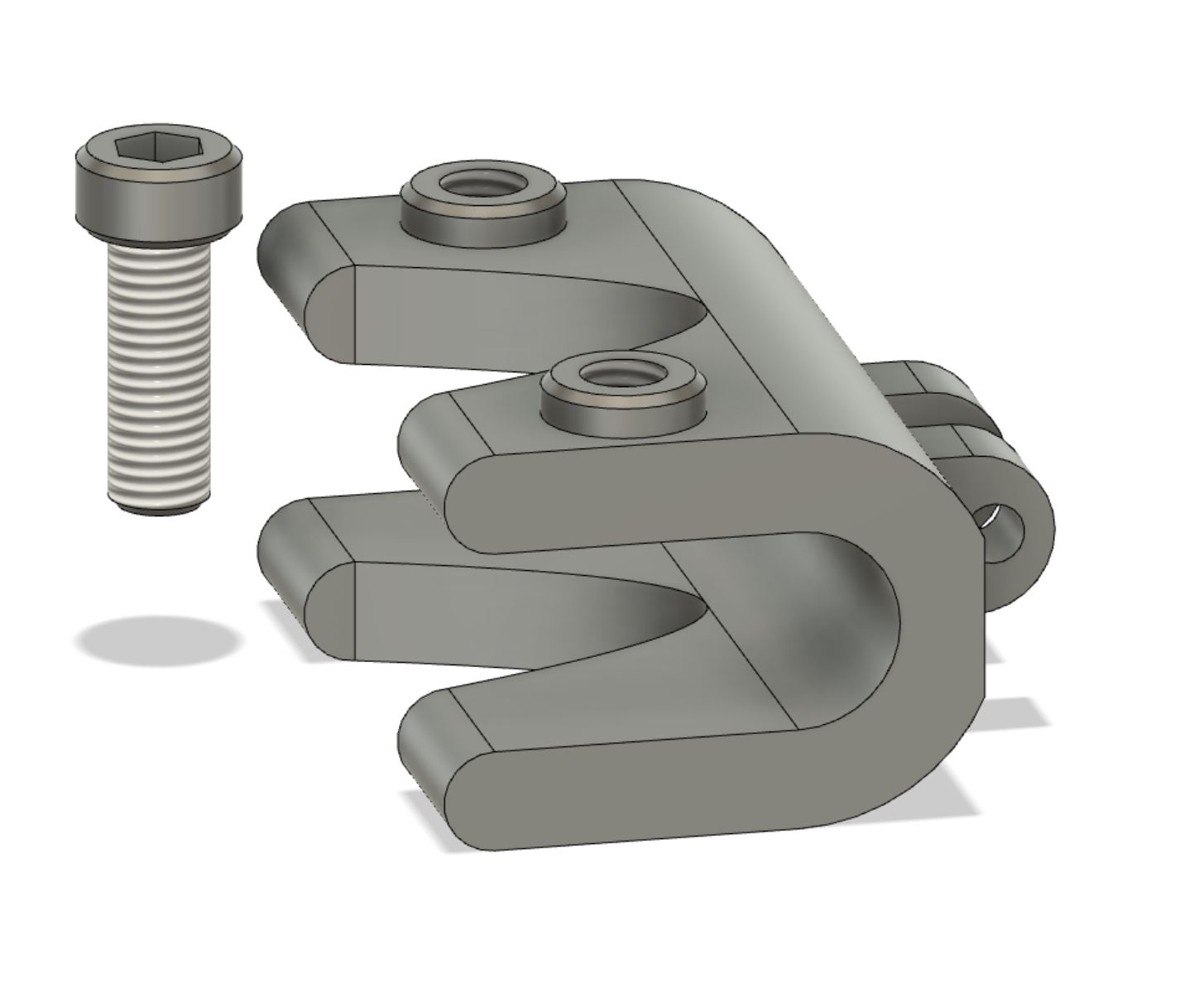
Now, to my amateur eye, this looked perfect! I made a nice threaded bolt with a hexagon head, and a couple of threaded holes in the mount.
I exported these objects, sliced them in Prusa slicer application and then printed them.
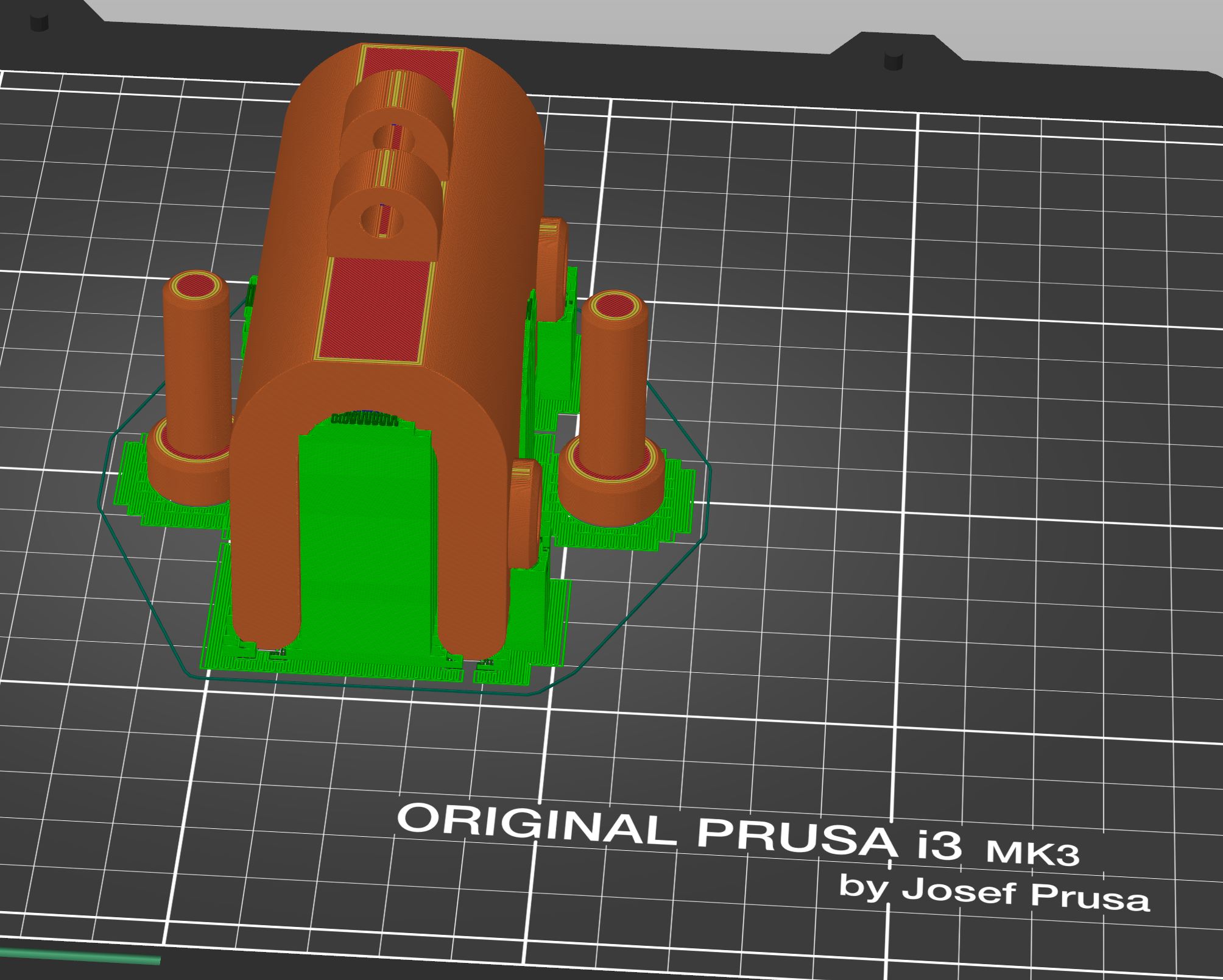
The print took some time and the morning after I realized I had made a mistake! I actually had made this mistake before, and I probably will do it again!
There were no threads! Both the bolts and the holes were completely smooth! Damnit!
As my trusty colleague smugly noted, “You’re supposed to select the modeled option, duh!”. So, for the rest of you, here is the dialog for modeling the actual threads in Fusion360!
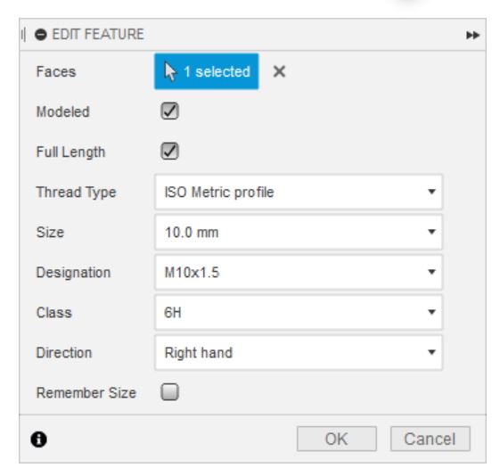
This is very strange behavior…
Below is the render with the thread.
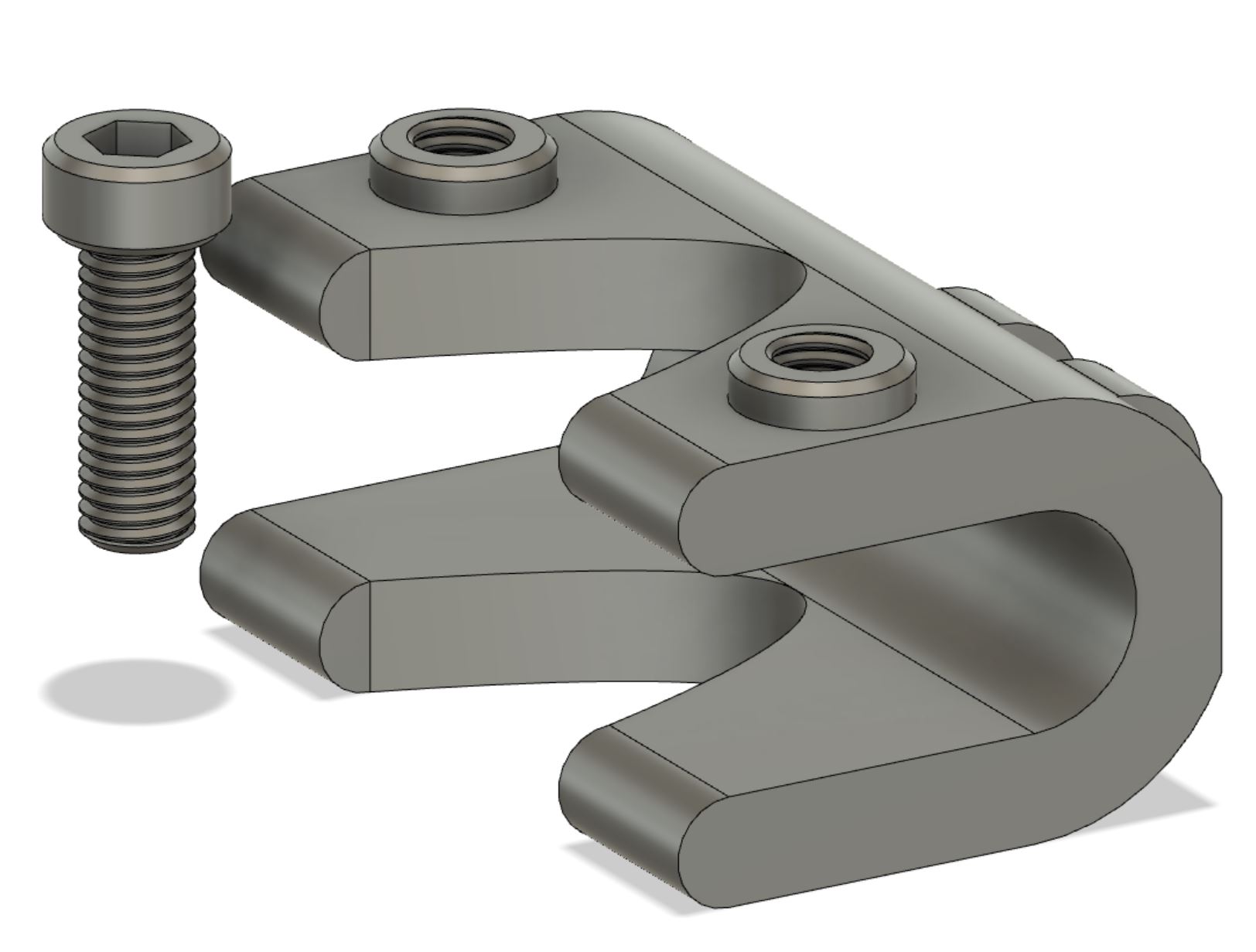
So, to the best of my knowledge, this has to do with rendering performance. I believe this behavior can be made better somehow. Anyways…!
Fortunately, I have a tap and die set and fixed the mount. I’ll then just use proper bolts, though the printed ones were quite nice!
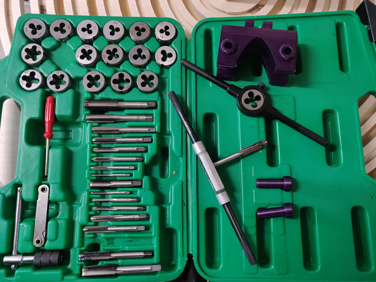
Tapping the mount:
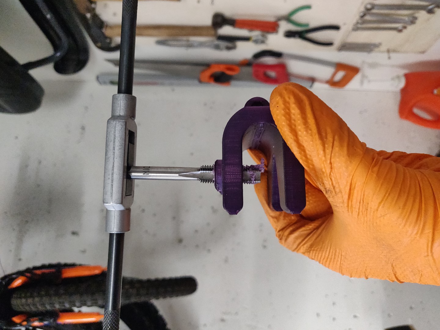
Fixed!
Front mount V2.0
Right before the final presentation, I realized the limitation of my I2C setup, which handled the communications between all boards. I had to shorten the distance between the parental and child units, so I made a new mount which sits in the middle console.
| Fusion file |
|---|
| Cupholder mount |
It sits quite well and fits the same mounts I had already made.
Rear mount
Next up, the rear mount! I grabbed the main measurements of the headrest axles.
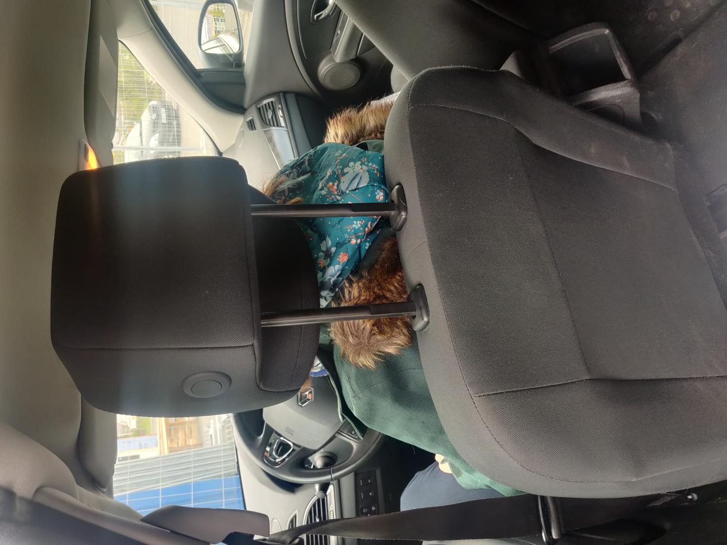
| Item | Measurement |
|---|---|
| Axle width | 14mm |
| Between axles | 110mm |
Here we see offspring V2.0. It can be categorized as a future user.
I would need to make all components water(drool)proof.

I Fusion 360, I made the rear mount.
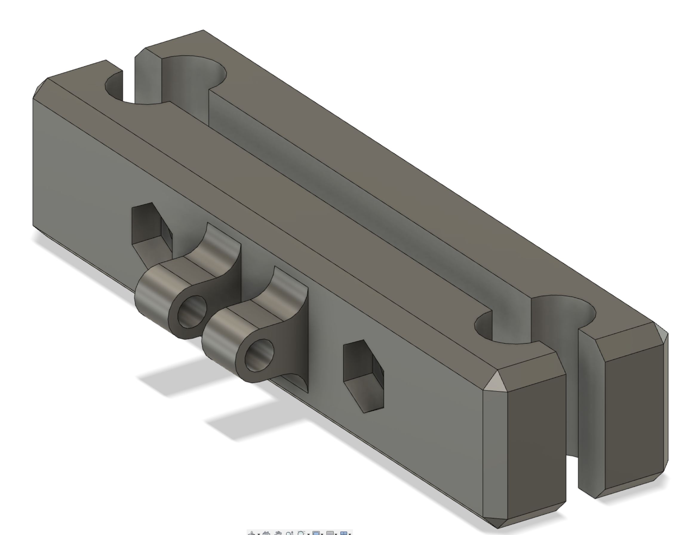
Exported as STLs, here are the files:
| File |
|---|
| Rear mount Front |
| Rear mount Back |
| Fusion360 project file |
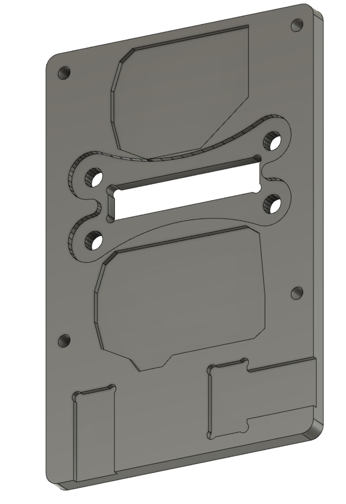
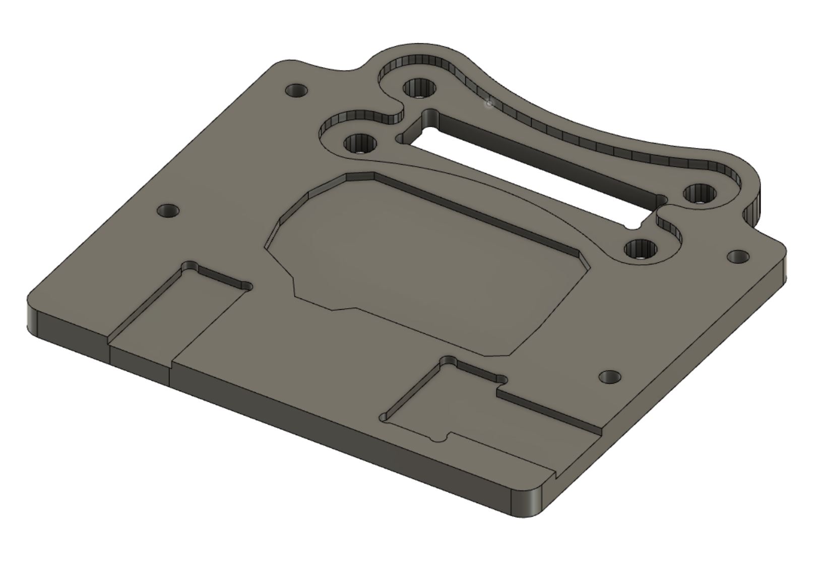
Plate mount
Next I designed this piece. It’s a fitting piece for the rear and front mounts, requiring a 6mm bolt to adjust the angle and tighten. A 50x10mm rectangular shape is cut into each backplate, along with 4 6mm bolt holes. The pieces then slide through the rect and is secured.
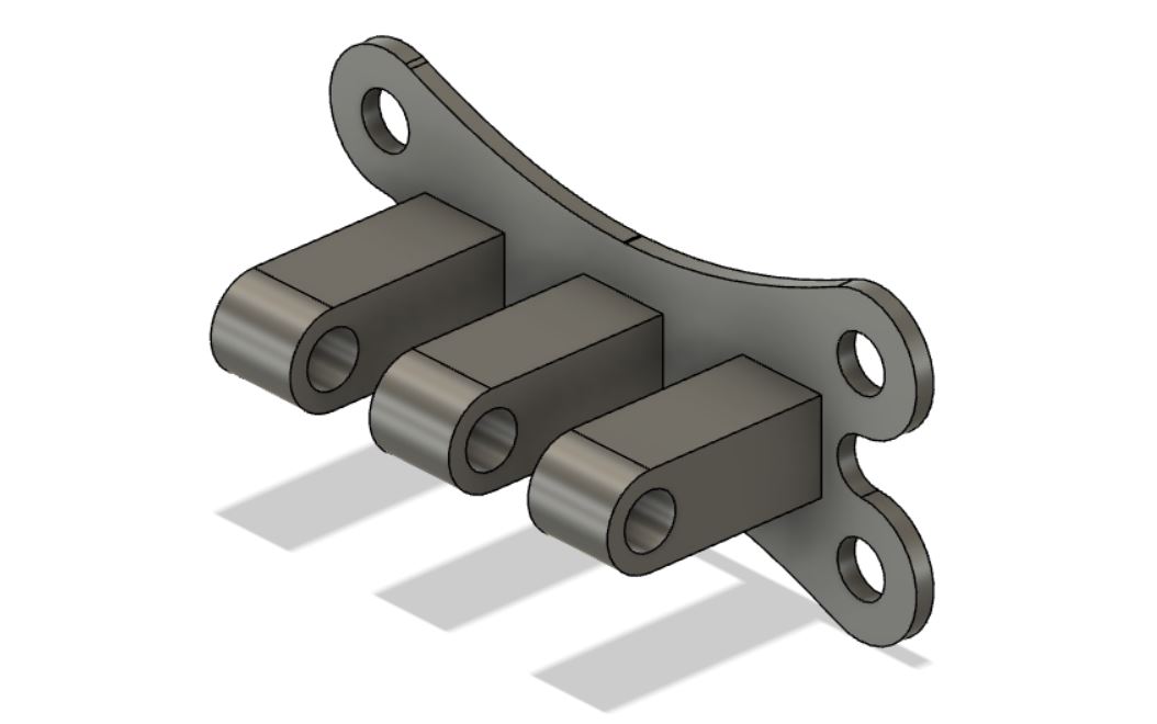
| File |
|---|
| Plate mount |
Putting it together
After the printing finished, I cut a piece of scrap MDF to create a realistic setup.
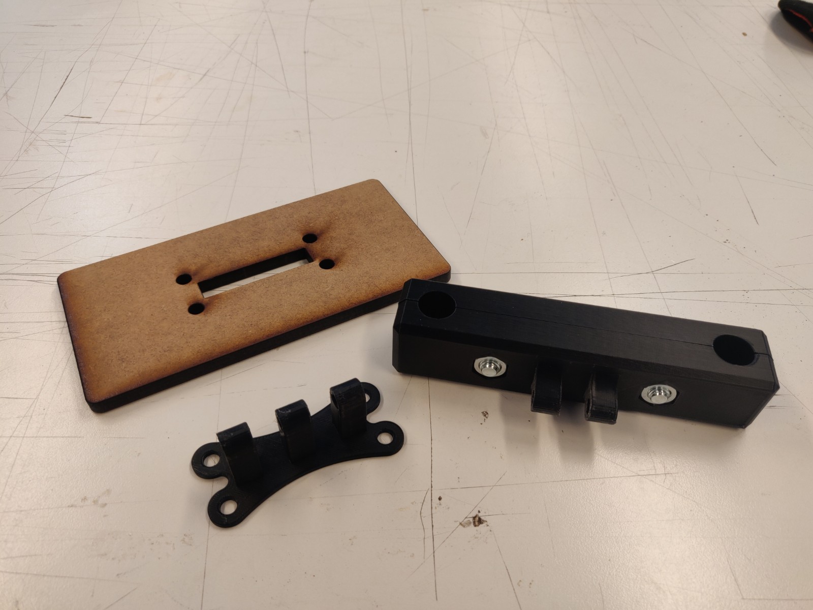
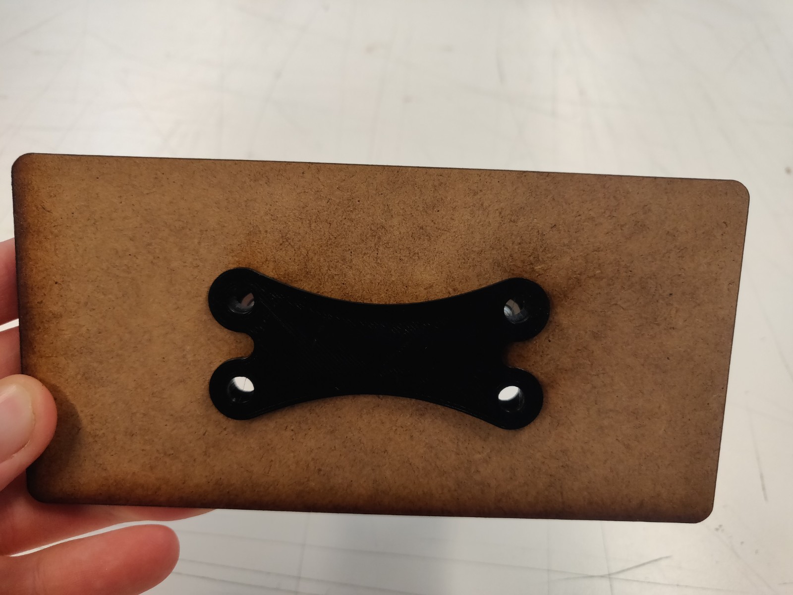
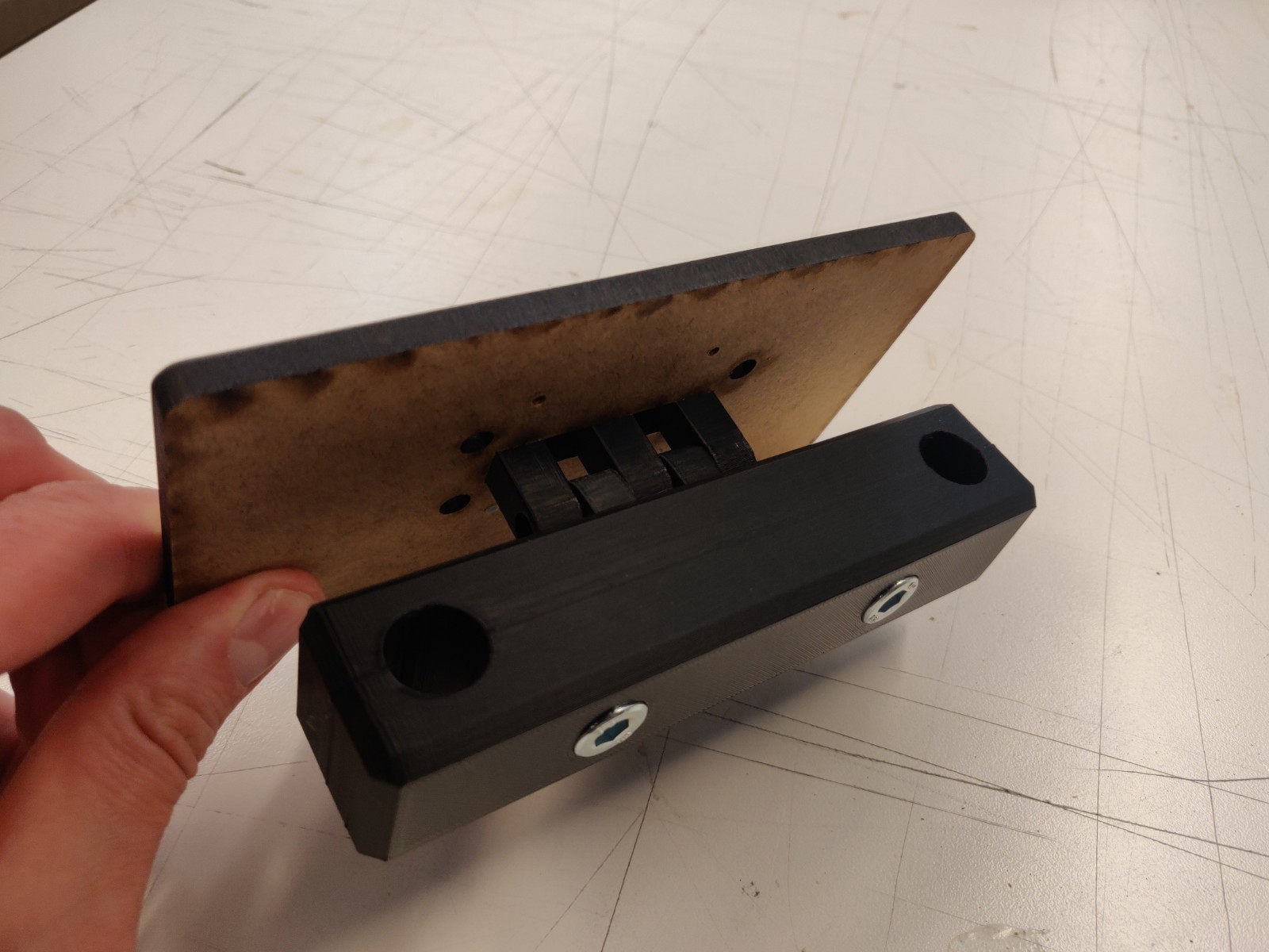
Nice! It’s just missing the 4 bolts to hold the backplate.
Boards
Next up is to make the boards I need for the minimum viable product, controlling for out-of-control-spiral-action before for the big presentation day!
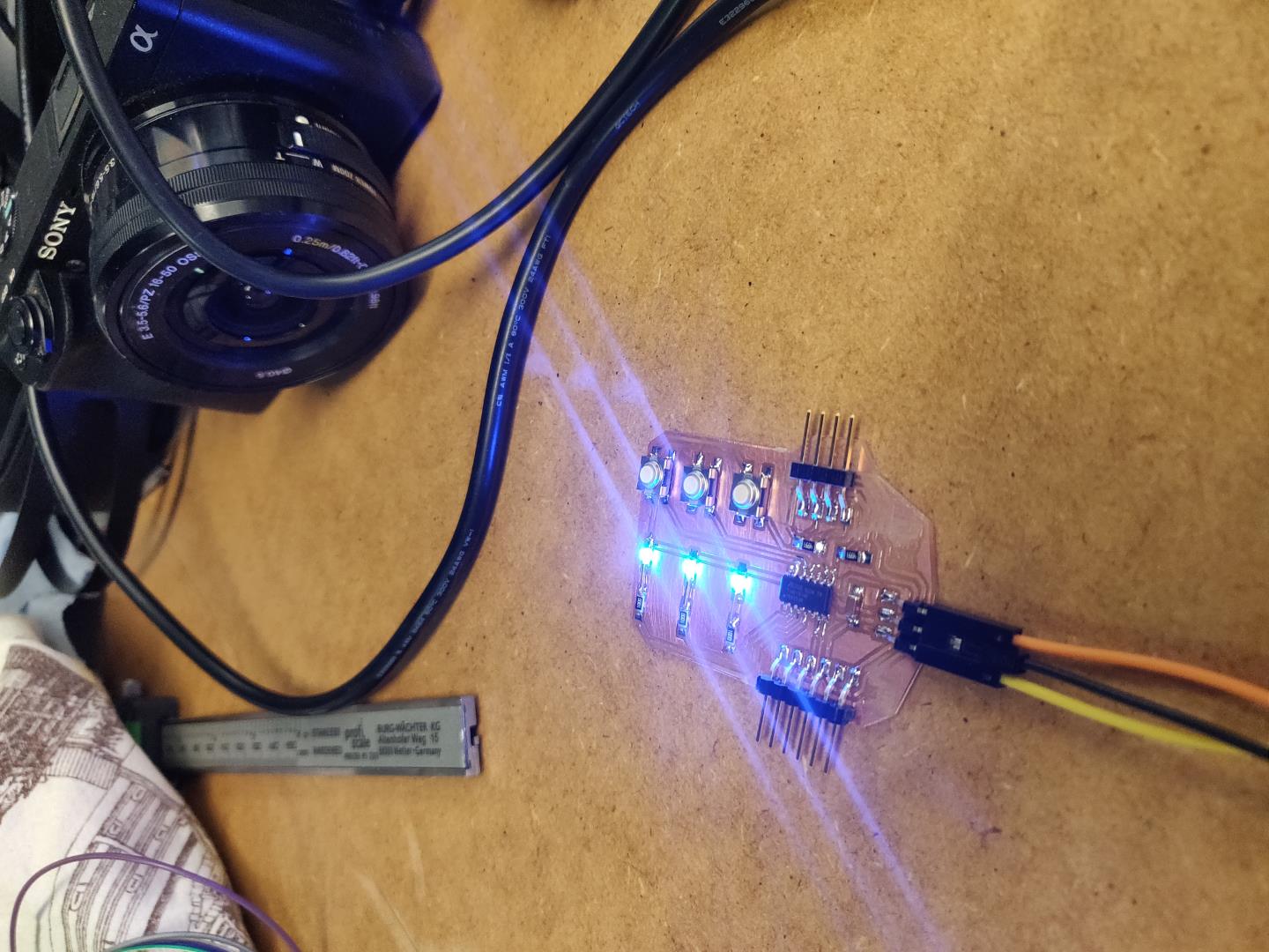
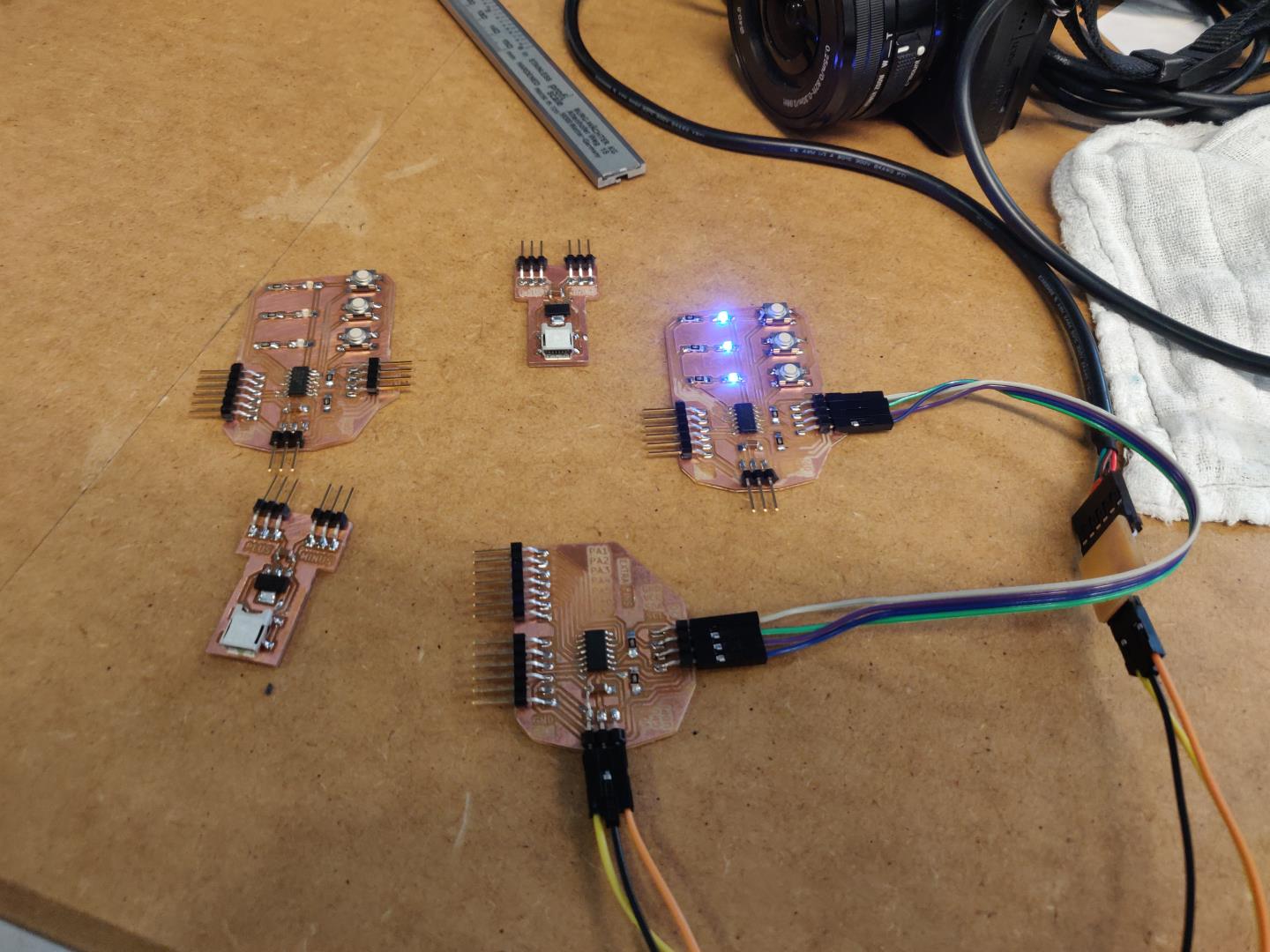
Controlling LED status with I2C:
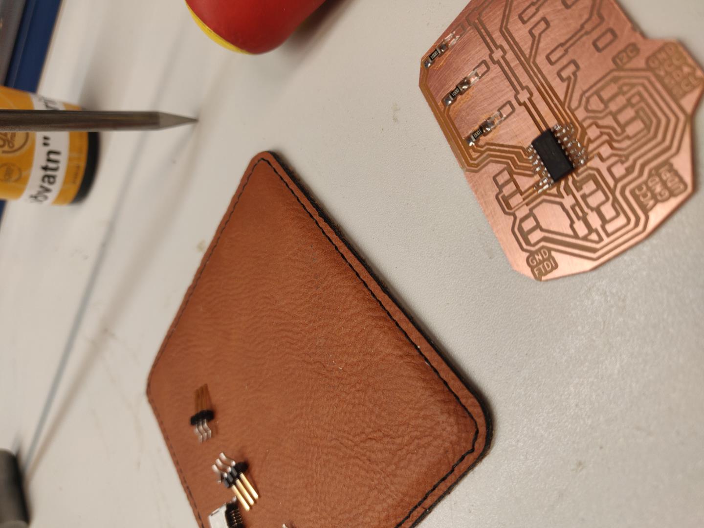
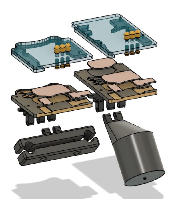
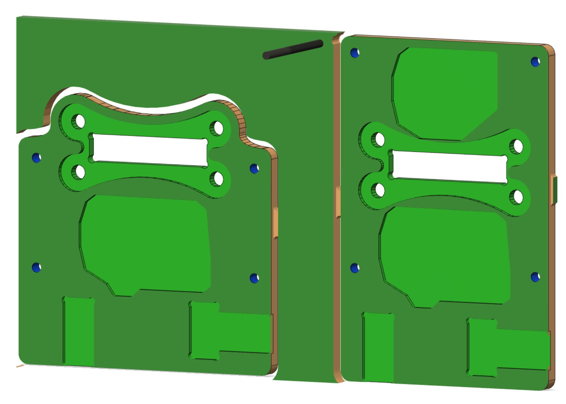
Packaging
Once I got the stuff actually working, it was time to package them!
Using KiCad to get the outlines of the boards into Fusion, creating a backplate, a plexiglass middle layer and cover was a nice process! Also using fusion, all items were combined to a single project to get the final “exploded” view used in the presentation.
| File |
|---|
| Combined Fusion project |
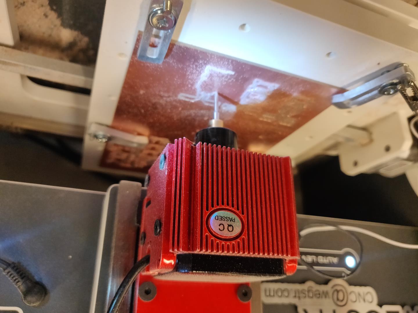
And before milling, the simulation
And the milling:
Took a bit of adjusting but finally all fit well!
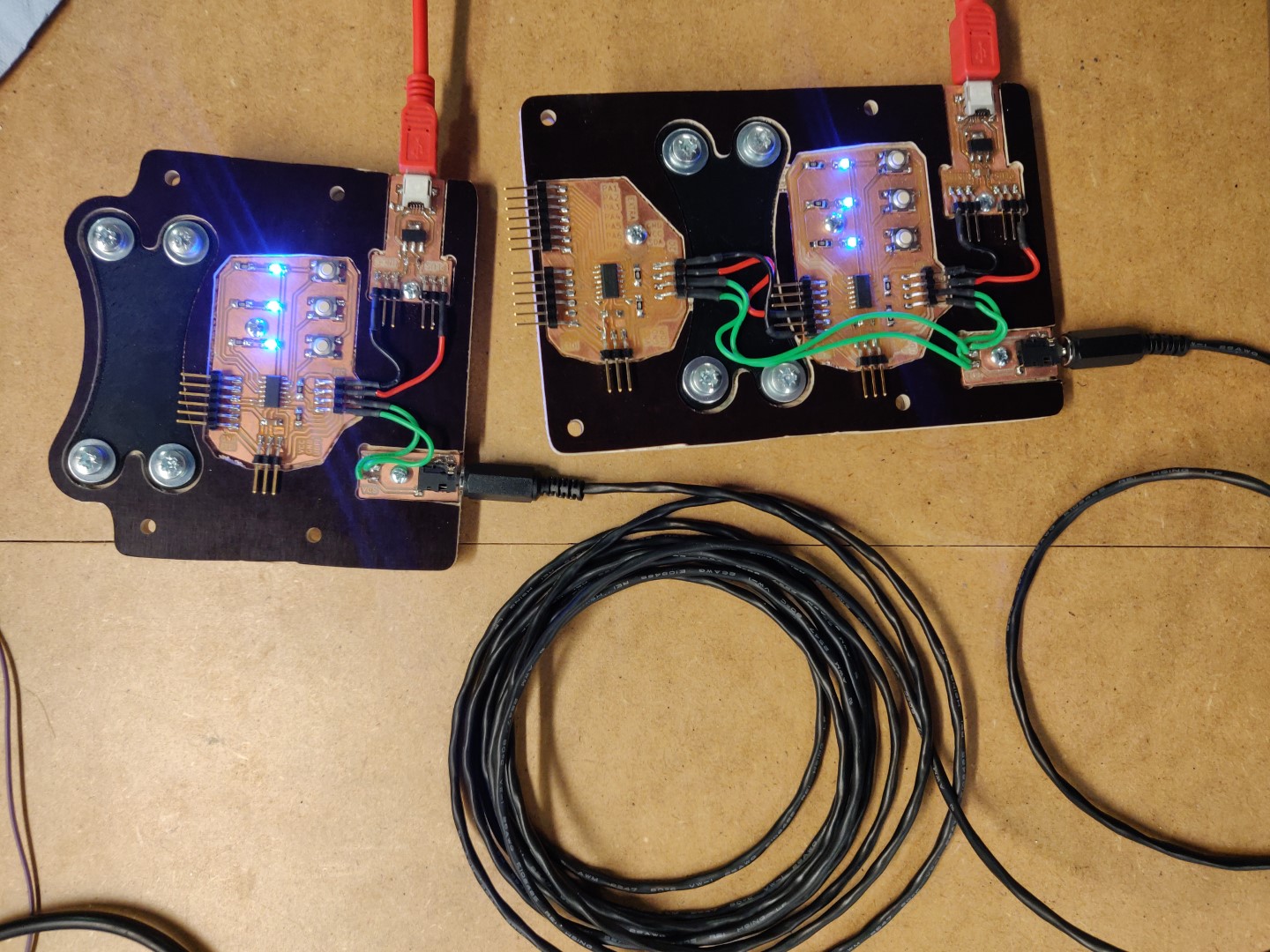
Mounting
Finally, mounting in the vehicle!
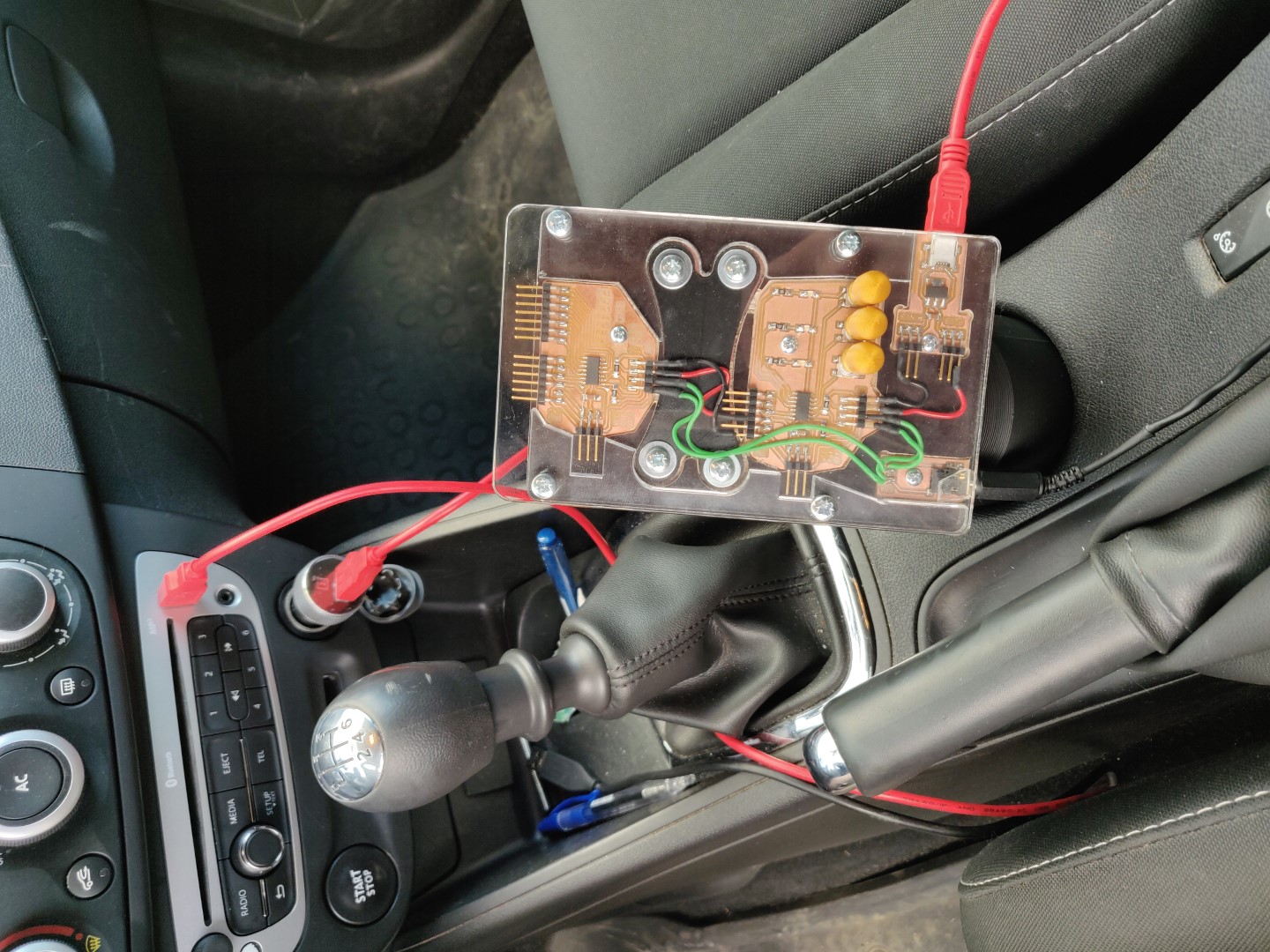
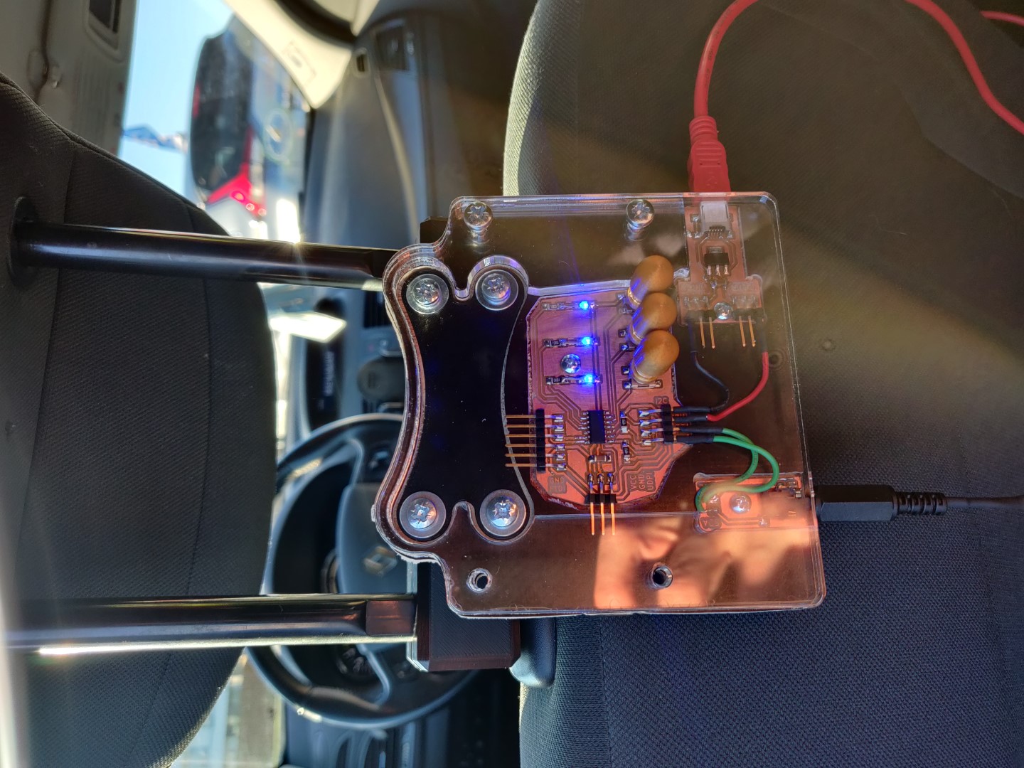
Brilliant!
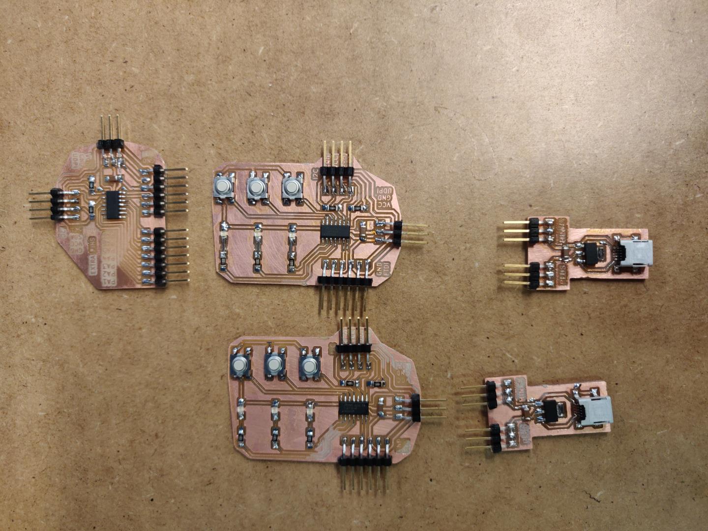
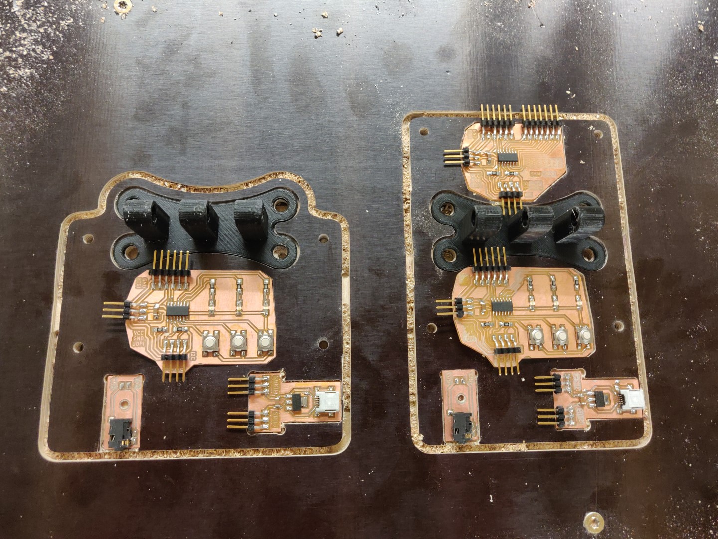
The boards
Quick overview of the electronic boards I made:
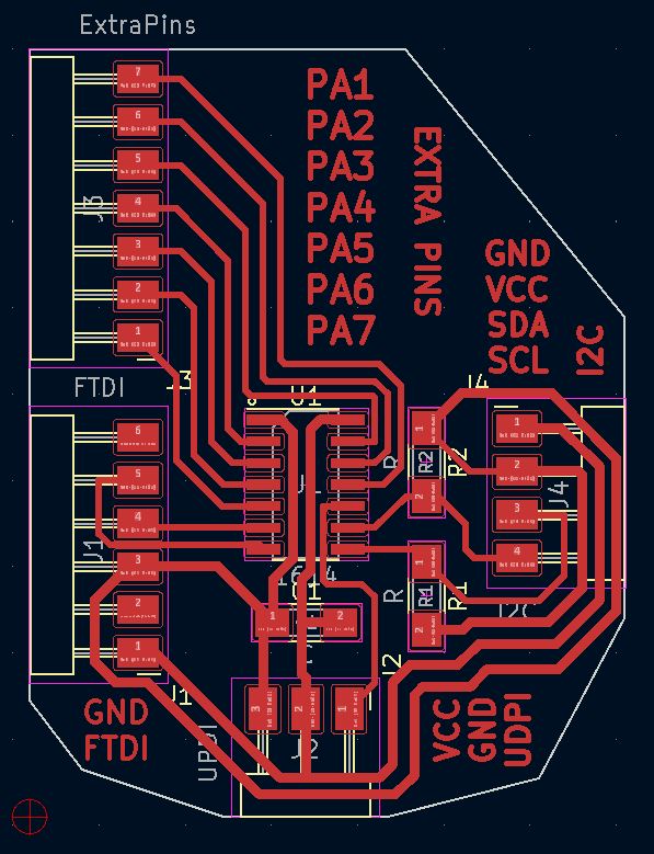
Control board
Handles the logic and syncs the LED statuses between button boards.
| Components | Qty |
|---|---|
| 4.99k res | 2 |
| 1uf cap | 1 |
| ATtiny 1614 | 1 |
| 1x3 pin header | 1 |
| 1x4 pin header | 1 |
| 1x6 pin header | 1 |
| 1x7 pin header | 1 |
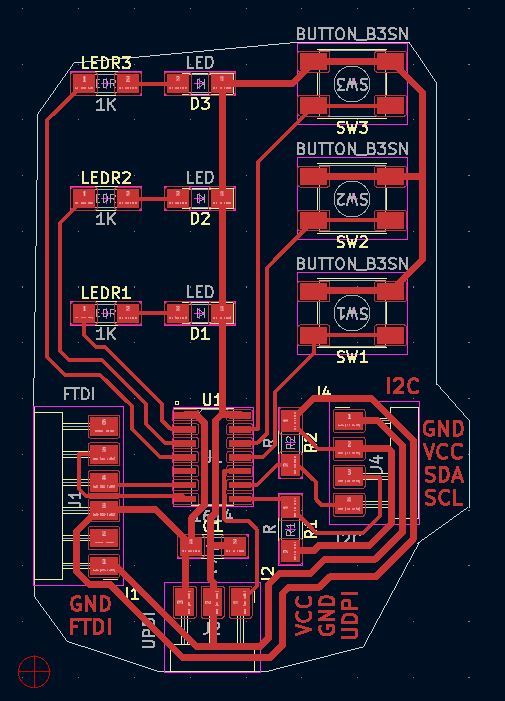
Button board
Takes input from user and turn LEDs on and off according the commands from the control board.
| Components | Qty |
|---|---|
| SMD LED | 3 |
| 1k res | 3 |
| 4.99k res | 2 |
| 1uf cap | 1 |
| BUTTON_B3SN | 3 |
| ATtiny 1614 | 1 |
| 1x3 pin header | 1 |
| 1x4 pin header | 1 |
| 1x6 pin header | 1 |
Power supply board
A simple USB connector with a 5V 1A regulator that supplies the boards. Should handle plenty of additional items.
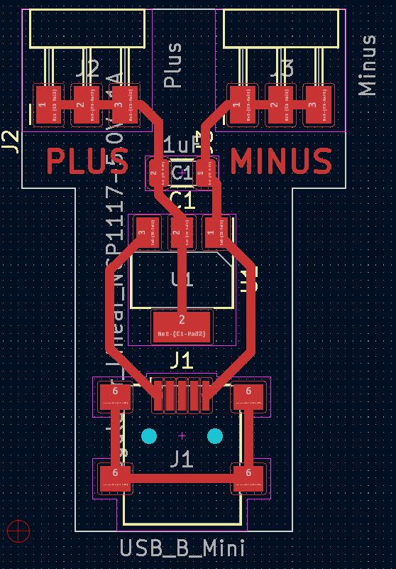
| Components | Qty |
|---|---|
| USB_B_Mini | 1 |
| Regulator_Linear_NCP1117-5.0V-1A | 1 |
| 1uF | 1 |
| 1x3 pin header | 2 |
Jack board
Mini jack connector is used to handle communications between the two units.
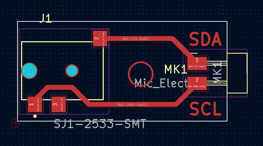
| Components | Qty |
|---|---|
| SJ1-2533-SMT | 1 |
| 1x2 pin header | 1 |
KiCad files
Below are the KiCad projects I created for the boards.
| Board |
|---|
| Control board (parental) |
| Button board |
| Power supply board |
| Jack board |
Control board code
The code for the control board:
//#include <Arduino.h>
#include <Wire.h>

byte ledArray[3] = {0,0,0};

void recieveEvent(int howMany){
  for (int i = 0; i < howMany; i++)
  {
    ledArray[i] = Wire.read();
  }
}

void sendLedArrayToBothBoards(){
  Wire.beginTransmission(1);
  for (int i = 0; i < 3; i++)
  {
    Wire.write(ledArray[i]);
  }
  Wire.endTransmission();

  Wire.beginTransmission(2);
  for (int i = 0; i < 3; i++)
  {
    Wire.write(ledArray[i]);
  }
  Wire.endTransmission();
}

void setup() {
  Wire.begin();
  Wire.onReceive(recieveEvent); // function that executes whenever data is received from writer
  sendLedArrayToBothBoards();
  delay(1000);
}

void loop() {
  sendLedArrayToBothBoards();
  delay(100);

  Wire.requestFrom(1, 3);
  for (int i = 0; i < 3; i++)
  {
    ledArray[i] = Wire.read();
  }

  sendLedArrayToBothBoards();
  delay(100);

  Wire.requestFrom(2, 3);
  for (int i = 0; i < 3; i++)
  {
    ledArray[i] = Wire.read();
  }
}
Button board code
#include <Arduino.h>
#include <Wire.h>

// Define buttons 1,2,3 as BUTTON_1, BUTTON_2, BUTTON_3 with PIN_PA1, PIN_PA2, PIN_PA3 respectively
#define BUTTON_1 PIN_PA1
#define BUTTON_2 PIN_PA2
#define BUTTON_3 PIN_PA3

// https://www.e-tinkers.com/2021/05/the-simplest-button-debounce-solution/
bool debounce_btn1() {
  static uint16_t state = 0;
  state = (state<<1) | digitalRead(BUTTON_1) | 0xe000;
  return (state == 0xff00);
}

bool debounce_btn2() {
  static uint16_t state = 0;
  state = (state<<1) | digitalRead(BUTTON_2) | 0xe000;
  return (state == 0xff00);
}

bool debounce_btn3() {
  static uint16_t state = 0;
  state = (state<<1) | digitalRead(BUTTON_3) | 0xe000;
  return (state == 0xff00);
}

// Define leds 1,2,3 as LED_1, LED_2, LED_3 with PIN_PA4, PIN_PA5, PIN_PA6 respectively
#define LED_1 PIN_PA4
#define LED_2 PIN_PA5
#define LED_3 PIN_PA6

byte ledArray[3] = {0,0,0};

void receiveEvent(int howMany){
  for (int i = 0; i < howMany; i++)
  {
    ledArray[i] = Wire.read();
  }
}

void writeEvent()
{
  Wire.write(ledArray, 3);
}

void setup() {
  Wire.begin(1);                // join i2c bus with address #1(parental button board) or #2(child button board)
  Wire.onReceive(receiveEvent); // function that executes whenever data is received from writer
  Wire.onRequest(writeEvent);   // function that executes whenever data is requested from reader

  // Set button pins as input_pullup
  pinMode(BUTTON_1, INPUT_PULLUP);
  pinMode(BUTTON_2, INPUT_PULLUP);
  pinMode(BUTTON_3, INPUT_PULLUP);

  // Set led pins
  pinMode(LED_1, OUTPUT);
  pinMode(LED_2, OUTPUT);
  pinMode(LED_3, OUTPUT);

  // Set leds off
  digitalWrite(LED_1, LOW);
  digitalWrite(LED_2, LOW);
  digitalWrite(LED_3, LOW);
}

void loop() {
  digitalWrite(LED_1, ledArray[0]);
  digitalWrite(LED_2, ledArray[1]);
  digitalWrite(LED_3, ledArray[2]);

  if(debounce_btn1()) {
    ledArray[0] = !ledArray[0];
  }

  if(debounce_btn2()) {
    ledArray[1] = !ledArray[1];
  }

  if(debounce_btn3()) {
    ledArray[2] = !ledArray[2];
  }

  delay(10);
}
Time spent on final project
I must admit, I did not keep a perfect timelog of the time I spent on the final project. But I can tell you this, it will take all the time you give it and will easily double that!
But to at least give a estimate of the ratios of how the time was spent:
40% Planning 40% Designing 10% producing (milling, soldering, cutting…) 10% Debugging, troubleshooting, optimizing
In these ratios I do not factor in sleepless nights and mental load outside of the actual office/lab!
Previously I’ve learned the importance of planning. Programming a function takes hardly no time at all, if you have already planned on what it should do, how, why, when and what for. This applies to all designs. This fact worked in my favour, I’m happy to report that most of the time, my designs at least kind of work OK, minimizing horrible late realizations of errors.
If you are a current student reading this, good luck and have fun! It’s a project, it’s not the single solution to all of the worlds problems, that comes later! ;)