9. Embedded Programming
Mission statement
This weeks offical missions are:
- Compare the performance and development workflows for other architectures
- Read the datasheet for your microcontroller
- Use your programmer to program your board to do something
The current status and plan
As mentioned in previous weeks, I’m having trouble with my programmer. During this weeks lecture, Neil mentioned that it is fine to use alternative solutions to get going with the programming, but with the aim of getting the programmer working as soon as possible.
To start with, I will use the FTDI cable with FTDI - UPDI board I made previously.
My plan
-
Use the Arduino IDE to program the board.
- I will at least create an .ino sketch to add functionality to my board.
- I might experiment with a different language to write the same code.
-
I will try to find out which chips I plan on using for the final project. If I settle on that, I will inspect the datasheet for that chip.
- Else I’ll look at the datasheet for the chip on my current board.
-
Experiment on getting the programming working on VSCode, possibly with the PlatformIO plugin.
-
I plan to spend time getting the programmer working. I might even switch to a different programmer, but I need to discuss this with my instructor as it impacts what chips I plan on using. This is the perfect week to dedicate time to it.
Let’s get going
Arduino programming
I started with using the Arduino IDE. Programs are called sketches in Arduino but behind that is a .ino file.
I create a new .ino file get tinkering. I looked at Arduino code samples provided on the Fab Academy site and just played around a bit, getting stuff to work.
One thing to note, just off the bat, is how to reference the pins on the chip. For my little board, I found the most comfortable method of identifying them is to look at the images provided by the megaTinyCore repo.
On this image of the chip, the legs/pins are numbered sequentially from 1 to 8, but on the chip it self there are no numbers. You get your reference by looking for the single marking on pin #1. Thats the little dot on the top left.
I just somehow found the PA[x] labeling nicer to work with, even though it makes no difference in the end. But it is important to find out the correct numbering/labeling for the chip you are using.
Holding and rotating my board so it facing the same way as the image, I can identify the pins by their position on the board. The pins I used are as follows:
| Pin | Name | Purpose |
|---|---|---|
| 3 | PA7 | Button |
| 7 | PA3 | LED |
The programming
When creating the board, I included a button and a LED. There may be a finite number of things you can do with only a single button and a single LED, but knowing that AI is all the rage these days I wanted to add a little character to the device. Then a (morbid) little sketch popped up in my mind.
So, after a bit of tinkering I wrote a little program for my board that mimics the (emotional) behavior of the butter-passing-robot.
| Arduino code |
|---|
Using the megaTinyCore and the settings shown on the image below, I could program the board.
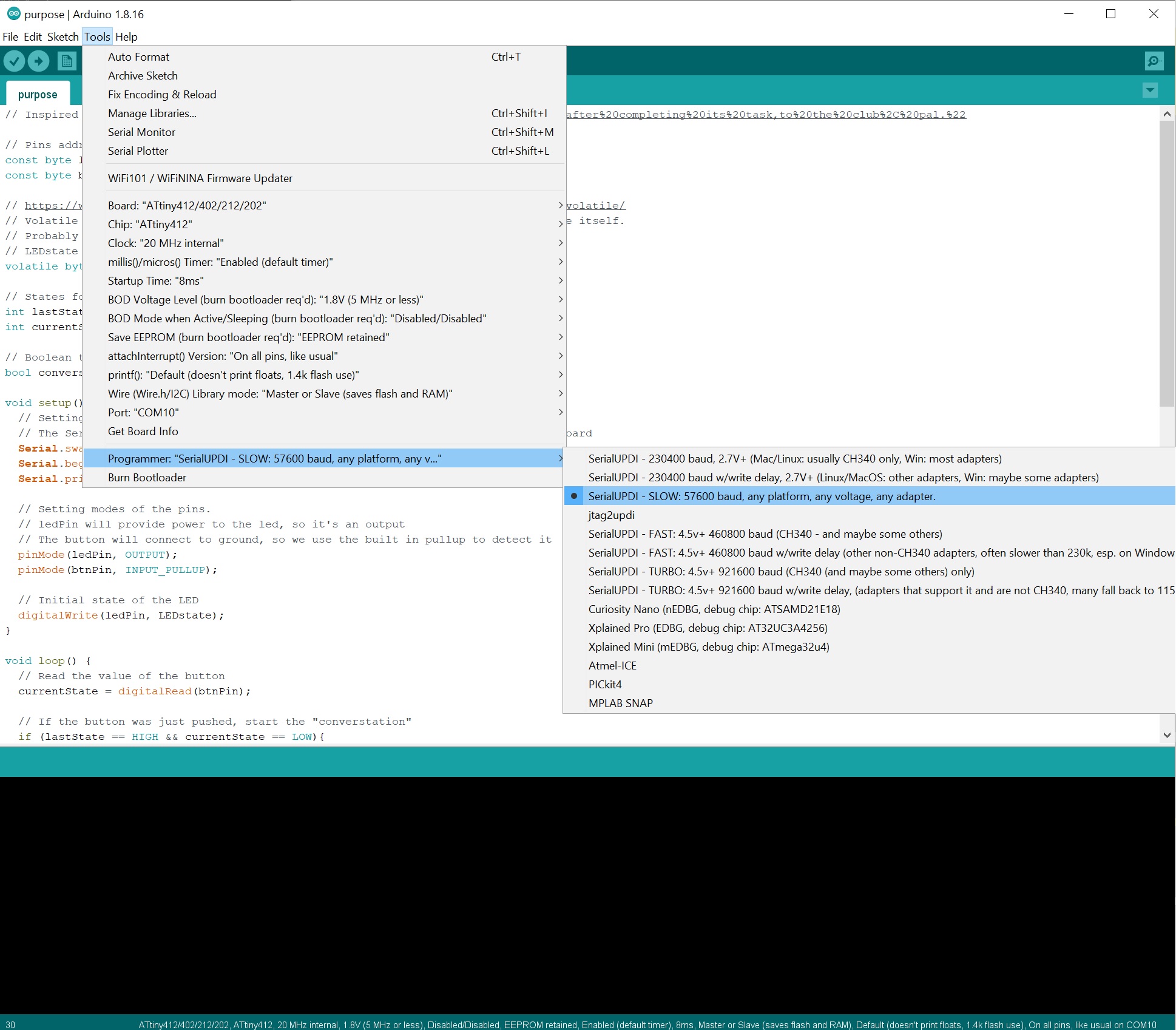
Items to take special notice of:
- Under
Boards, selectMegaTinyCoreandATtiny412/.... - Under
Chip, selectATtiny412 - Under
Port, I select the port which my FTDI cable connects to,COM10in this case. - Under
Programmer, I selectSerialUPDI - SLOW....
Lo and behold!
We now the board is programmed and ready to go.
Let’s push the button and see what happens!
Arduino code
I believe I have commented the code above sufficiently, but here are a few notes that I wanted to mention.
When creating a new sketch in Arduino IDE you are presented with the following snippet:
void setup() {
    // put your setup code here, to run once:
}

void loop() {
    // put your main code here, to run repeatedly:
}
So, as the name suggests, the setup function is called once, and the loop function is called repeatedly.
Before either are ran, you might want to set up some variables, constants or other parameters that are global to the program. These would be declared at the top of the file. Let’s say for example, that you would want to set a upper and lower limit to use in your program, and these limits should not be modified during the runtime of the program. They would be categorized as constants. You would declare them as such:
const int upperLimit = 10;
const int lowerLimit = 0;
Then for example, you would use them in your code:
if (analogRead(A0) > upperLimit) {
    digitalWrite(7, HIGH);
} else if (analogRead(A0) < lowerLimit) {
    digitalWrite(7, LOW);
}
If you were to try to modify these values, you would get an error.
Within the setup function, you would for example, set up the pins and their modes. A pin might be set to input, output, or analog. Another common thing to run within the setup function is to start serial communications.
The loop function is where you would put your code that you want to run repeatedly. This is similar to a main function in other programming languages. It where most of your logic would go, and it would be called repeatedly.
Now you could also, and it’s highly recommended, break your main loop into smaller functions. This would allow you to call the functions from within the loop function which adds clarity to your code and it’s much easier to read, understand and modify. So a basic example of a function would be:
void myFunction() {
    // put your code here
}
Then within the loop function, you would call the function:
myFunction();
This was just a small bit of info that I thought might be useful for newcomers. There is plenty of reading material, all over the web.
VSCode && PlatformIO
Next order of business is to get the programming working on VSCode. I prefer to use VSCode as my main editor, both at work and personally. I find it to be quite nice, there is plenty of extensions, it is cross platform, and it is easy to get started.
On top of VSCode, I added the PlatformIO plugin a few months ago, almost by accident. I was kind of blown away of how easy and nice it is to use. I first tested it on Arduino Uno and Nano, but now lets try it with my board.
Setting up
I present here a fresh VSCode window, with nothing open.
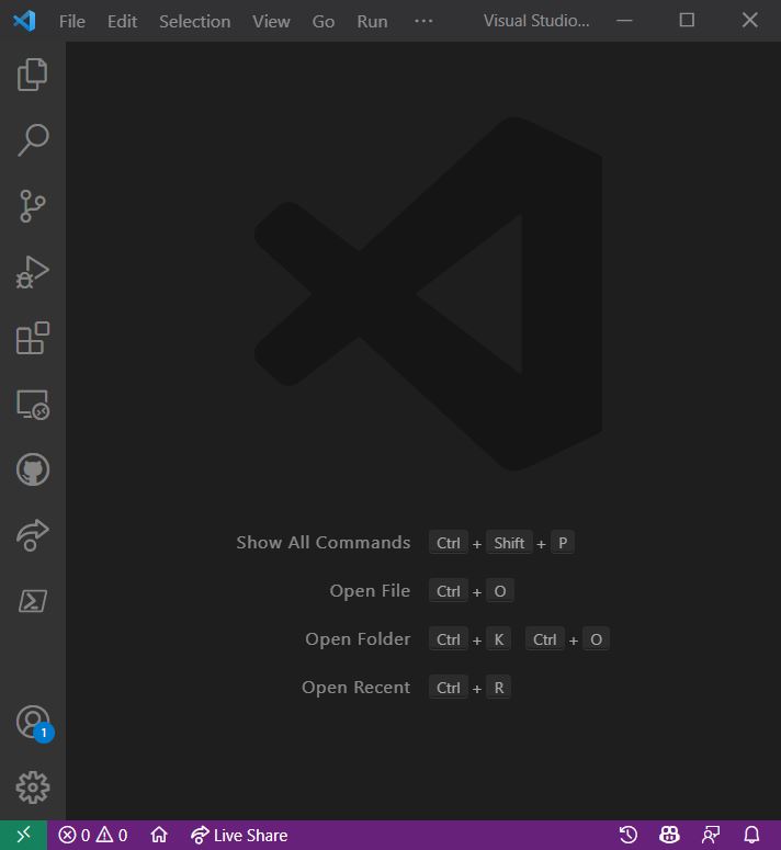
To start a new PlatformIO project in VSCode, start the editor and click the little home button in the bottom left.
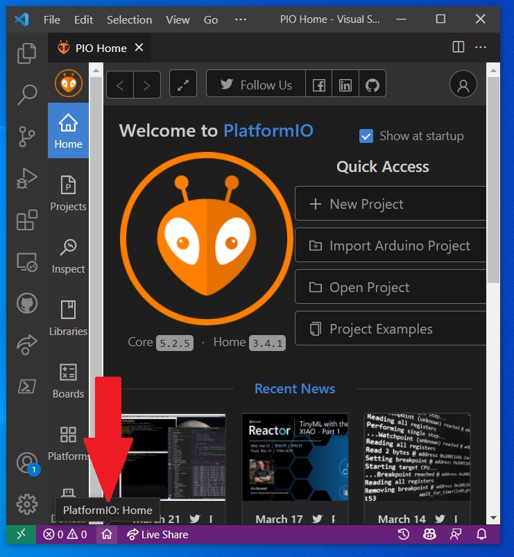
You are then greeted with the main PIO menu.
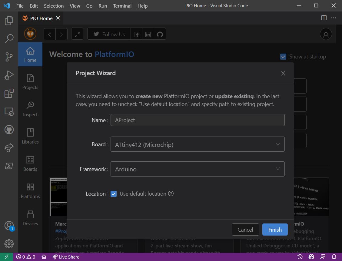
Select New project, give it a name and then start the magic. Just find your board/chip! I entered 412 and it found ATtiny412 (Microchip)!
Use the default location for the files, or select a directory that suits you.
You are then presented with the IDE open in you new projects directory.
There are multiple folders and files present already, but the most important for us now are the src folder and the platformio.ini file.
Within the src(source) folder you will find your main.cpp file. This is similar file to the one you would use to write your code within Arduino IDE.
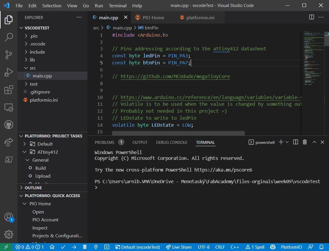
Notice the top line:
#include <Arduino.h>
This imports everything Arduino specific.
Below this I just copy and paste my code from the .ino file above. One thing I notice, is that intellisense warns me about parts of the code not recognizing functions in it. Turns out that Arduino IDE allows you to declare functions below where they are used. This might be considered a good thing, because it makes it easier to write code, but it is contrary to some conventions and coding rules (which I broke earlier!). Once I moved the functions above the loop function, I got rid of the errors.
Building and uploading
Under the PlatformIO project task menu, selecting Build successfully builds the project! Being the optimist I am, I then hit Upload and it did … not work!
Trouble!
As it turns out, you need to supply the IDE with the same information that you would as if you were programming the chip from the terminal windows. In Arduino IDE you set most of these settings from within the GUI. In PlatformIO, edit the configuration file platformio.ini.
platformio.ini
When starting a fresh 412 project your platformio.ini file should contain these settings:
[env:ATtiny412]
platform = atmelmegaavr
board = ATtiny412
framework = arduino
I searched the for guidance and found this solution:
After adjusting it for my board, I was able to successfully build and upload the project.
[env:ATtiny412]
platform = atmelmegaavr
board = ATtiny412
framework = arduino
upload_speed = 115200
upload_flags =
    -d
    attiny412
    -c
    $UPLOAD_PORT
    -b
    $UPLOAD_SPEED
    -v
upload_command = pyupdi $UPLOAD_FLAGS -v -f $SOURCE
| VSCode/Platform.io project |
|---|
| Project file |
Building and uploading
Now we are ready to build and upload the project.
Within the PlatformIO project task menu, select Build. This will build the project and notify you if there is anything wrong with the code.
Build
Upload
micro:bit
The micro:bit is “is a pocket-sized computer that introduces you to how software and hardware work together. It has an LED light display, buttons, sensors and many input/output features that, when programmed, let it interact with you and your world.”
It’s a brilliant little thing to experiment with, easy to use and real cheap. Chances are that your local school or Fab Lab has plenty of them available for trying them out.
How to use
There are a few ways to program the microbit, one of the simplest is to do it in browser!
For python programming, you visit this site, for the block editor you visit this site. I chose the python one.
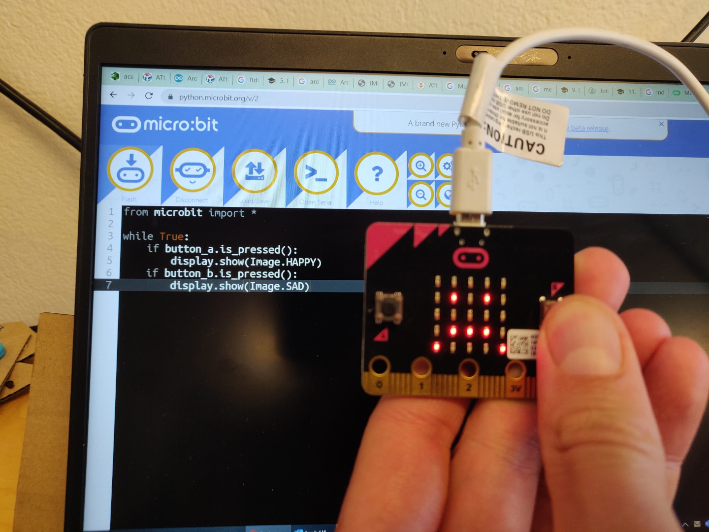
We are then presented with a screen like this:
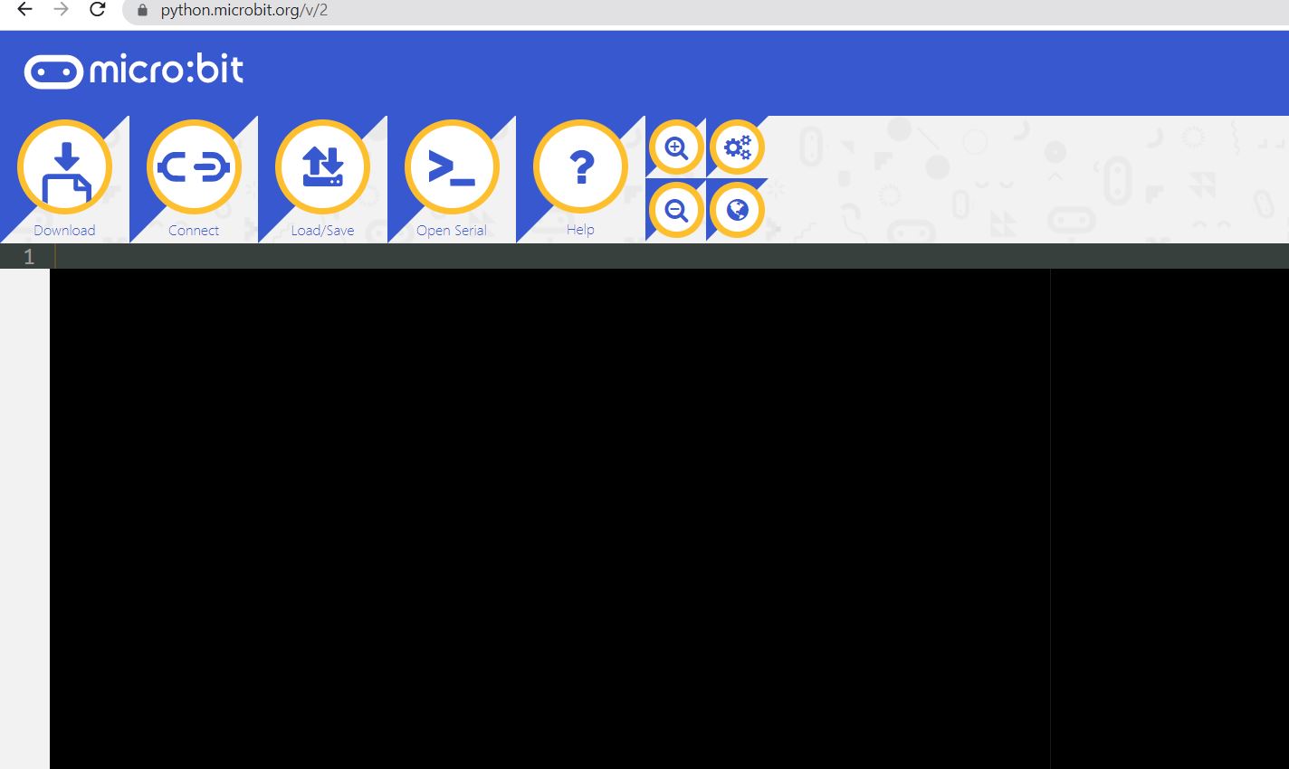
To connect the board, use a USB cable to connect the board to your computer and select “Connect”. (Note, chrome is recommended for this)
You should be presented with a dialog which lists your micro:bit, select it and “Connect”.
Now you can program it using the browser, simple as that!
Here is the documentation for the python part, which covers a lot of stuff!
Using this bit of code from the site, we now have input (buttons) and output (the led screen)
from microbit import *

while True:
    if button_a.is_pressed():
        display.show(Image.HAPPY)
    if button_b.is_pressed():
        display.show(Image.SAD)
Pressing button A (left)
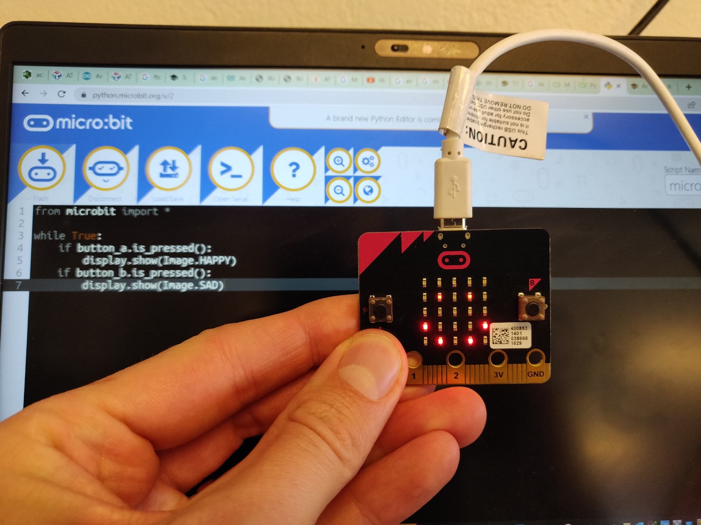
Pressing button B (right)
Loads of fun possible.
Microbit classroom
There is also a microbit classroom, which is really nice! Last year I presented the classroom during a scandinavian school learning summit, which the FabLabs in Iceland helped organize, where the microbit was introduced, teachers experimented with them and then we played treasure hunt. I adjusted the code a bit, hid plenty of microbit around the school and teacher hunted for them! Brilliant times!
Datasheets
I did not manage to carve out the time to read all 479 pages of the complete datasheet. I did however, found a link to a summary datasheet which I believe should suffice =)
| Summary datasheet |
|---|
| ATtiny412 (summary) Datasheet |
Since I might actually use the SAM D11 chip, I grabbed the summary PDF for that one also, for safe keeping.
| Summary datasheet |
|---|
| SAM d11 (summary) Datasheet |
Datasheet info
This update is at a much later time. Turned out I did not really use the D11C chip, but used the 412 a bit. The most useful thing for me from the datasheet, was the pinout!
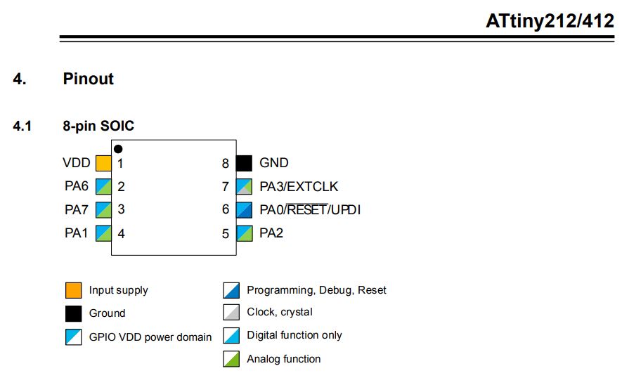
I used this quite a bit, very handy to view the actual pin number and the PAx, which I found handy to use in the code. Also which can handle analog and/or digital functions and where the UPDI pin is!
The datasheet also mentions three different sleep modes:
- Idle with All Peripherals Running and Mode for Immediate Wake Up Time
- Standby
- Configurable Operation of Selected Peripherals
- SleepWalking Peripherals
- Power Down with Wake-up Functionality
I did not use or need these functionalities for my projects, but it’s good to know the chip has them if working with setups that are sensitive to power usages, such as with solar or other battery powered projects. The summary datasheets do not cover them in depth, for further information one must look at the proper documentation, I will not cover that here since I did not use this.
Summary
I have now successfully built and uploaded my project to my ATtiny412 board, using both Arduino IDE and VSCode + PlatformIO. The project adds basic functionality, such as button input, led output, serial output to the ATtiny412.
I find the environment within VSCode to be much nicer to work with than Arduino IDE, in pretty much every way.
I have grabbed and skimmed the datasheets.
Wheee!
Important update!
Very nice! After finishing the final project recharging my mojo a bit, I made another attempt at the UPDI-programmer, which proved successful.
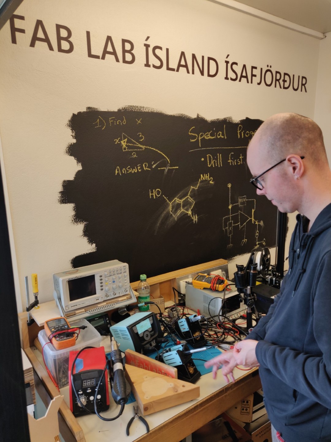
Yet again, I’m at Ísafjörður and met up with my instructor Doddi, but I actually met his alter-ego the uber-impressive DJODDI.
For this attempt, I used the fancy boards I had made in a board house.
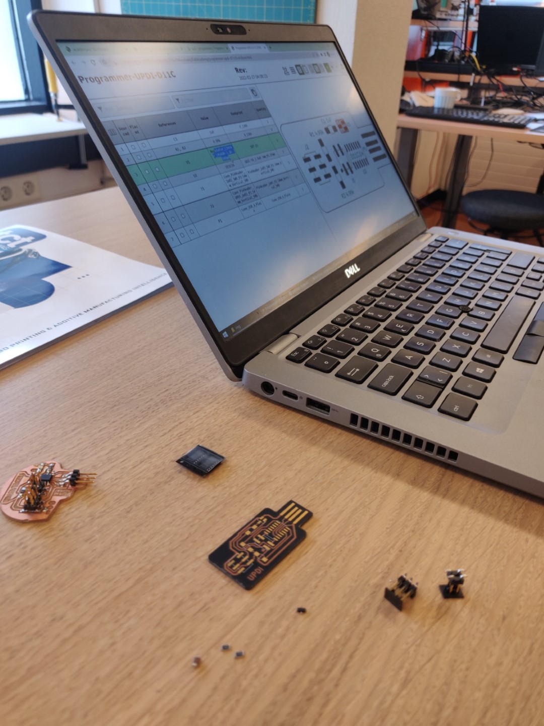
Pictured are the fancy board, my old output board and the components needed for UPDI programmer.
| Component | Pcs |
|---|---|
| D11C | 1 |
| 4.99k R | 2 |
| 0.1uF C | 1 |
| 3.3v 0.1a regulator | 1 |
| 2x2 pin header | 1 |
| 2x3 pin header | 1 |
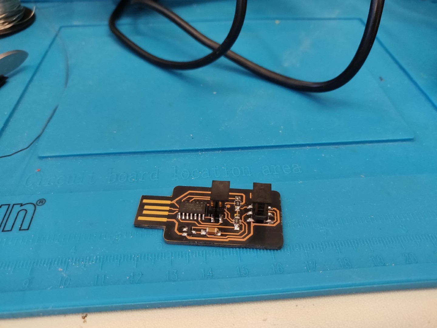
Looking nice! Pictured below, is a SWD programmer to use with it.
Following the same steps as before, but maybe with more confidence, experience, luck and a much cooler looking board it was a success! I manage to flash my UPDI based output board!