10. Molding and Casting
This weeks mission:
-
Review safety data sheets
-
Make test casts
-
Design a mold
-
Mill a mold
-
Create a cast using the mold
My plan
My original idea was to cast a bumper/safety case around the child unit for my final project.
But since I have not decided yet on final dimension of the thing, and it will be a bit large, I find it to be a waste of materials to cast such a thing if it will then turn out to not fit at all!
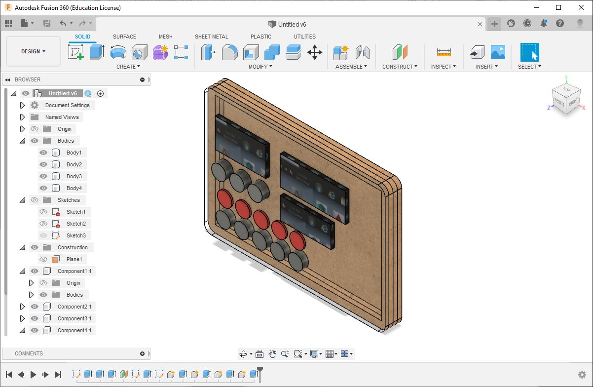
So what I want to do is to create a mini version of it, using similar form but scaled down.
Materials
These are the materials I’ll be working with:
- A high speed machining wax block with the following dimensions:
| Dimension | mm |
|---|---|
| Length | 175 |
| Width | 75 |
| Height | 37 |
(At this moment in time I do not have the wax supplier/makers name)
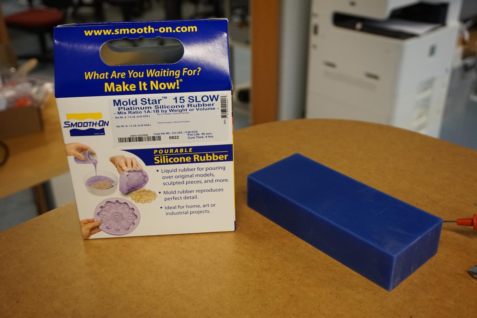
- Mold Star 15 SLOW from Smooth-On
The silicone safety sheet states:
-
Use in properly ventilated area (“room size” ventilation). We have a air circulation system in the room.
-
Wear safety glasses, long sleeves and rubber gloves to minimize contamination risks.
-
Material should be stored in a dry, cool place.
-
KEEP OUT OF REACH OF CHILDREN!
Additional note about FAST vs SLOW silicone
While reading this page, you’ll see in the “Casting #1” I found out that the FAST curing version of the silicone is actually FAST!
| Name | Curetime |
|---|---|
| Mold Star™ 16 FAST | 30 minutes |
| Mold Star™ 15 SLOW | 4 hours |
Please keep this in mind!
Same safety precautions and mixing ratios apply to the FAST and SLOW versions.
For this project, I want to use just the single wax block. I’m thinking of making a two sided mold, milling each part into one half of the block, then cutting it in two to mate them together. I’m rather concerned with conserving materials and must also keep time on the mill in check.
Design
I create a new design in Fusion 360, with the above considerations in mind.
The scaled down placeholder for the child unit
I create a object with dimensions of:
| Dimension | mm |
|---|---|
| Length | 65 |
| Width | 50 |
| Height | 20 |
Here is the simplified & minified version:
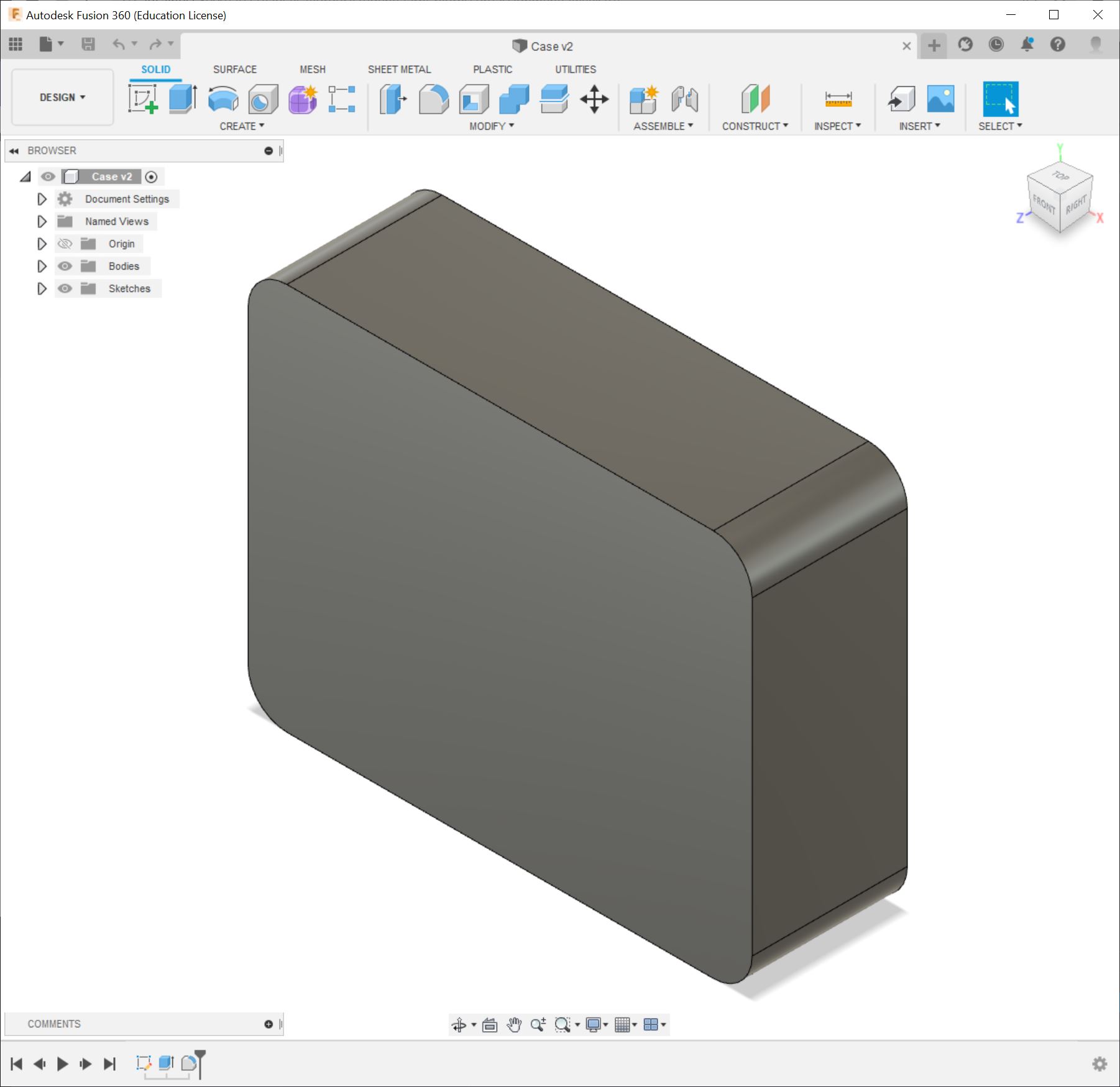
The mini case
I then copy the object and add 5mm to each side using the Press pull function. Adding a flange to each side, I now have a simple smooth outer object which will be the case!
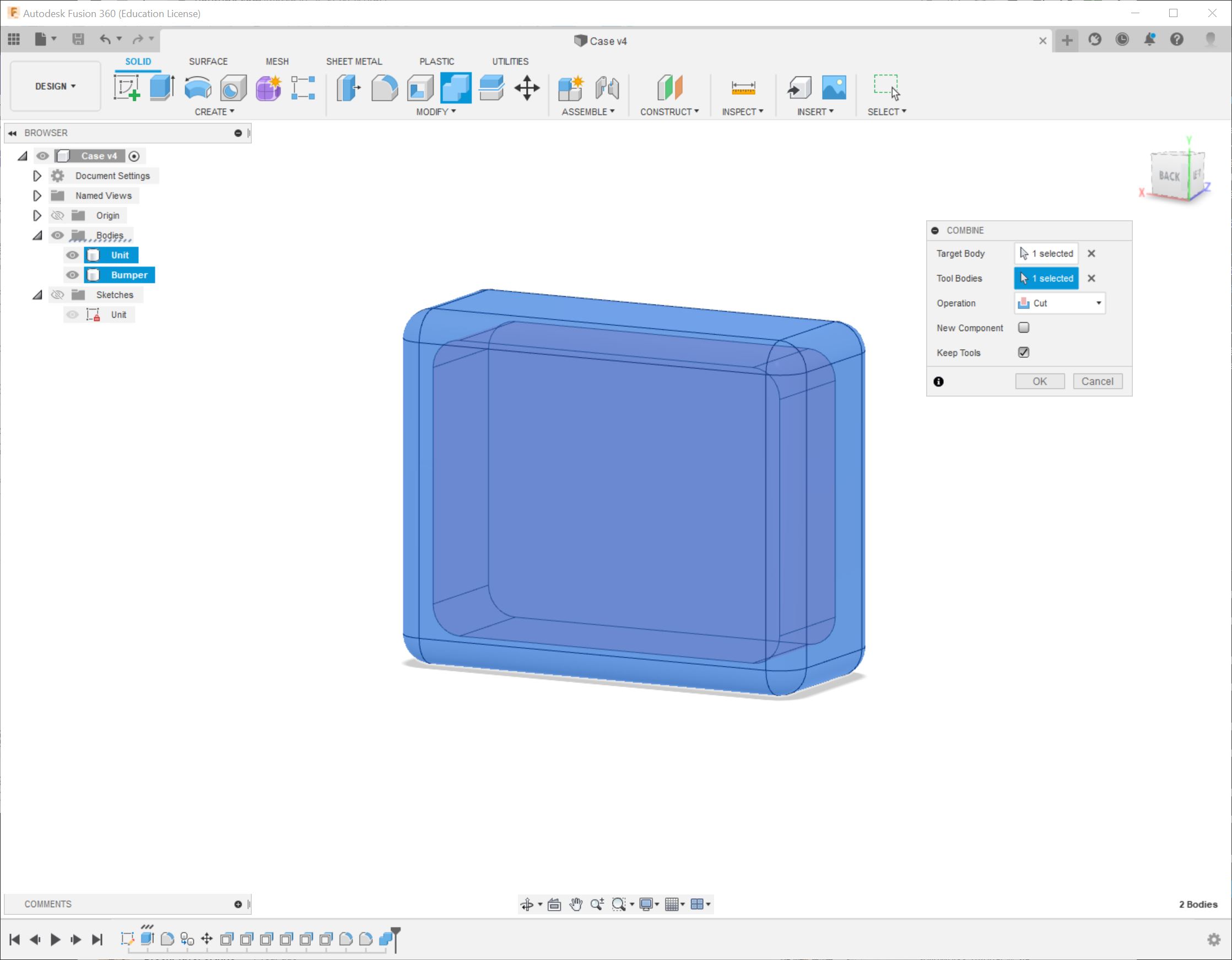
Using the Combine function, I cut the unit from the case body. Remember to select Keep tools if that suits you, else the body you used to cut will be discarded.
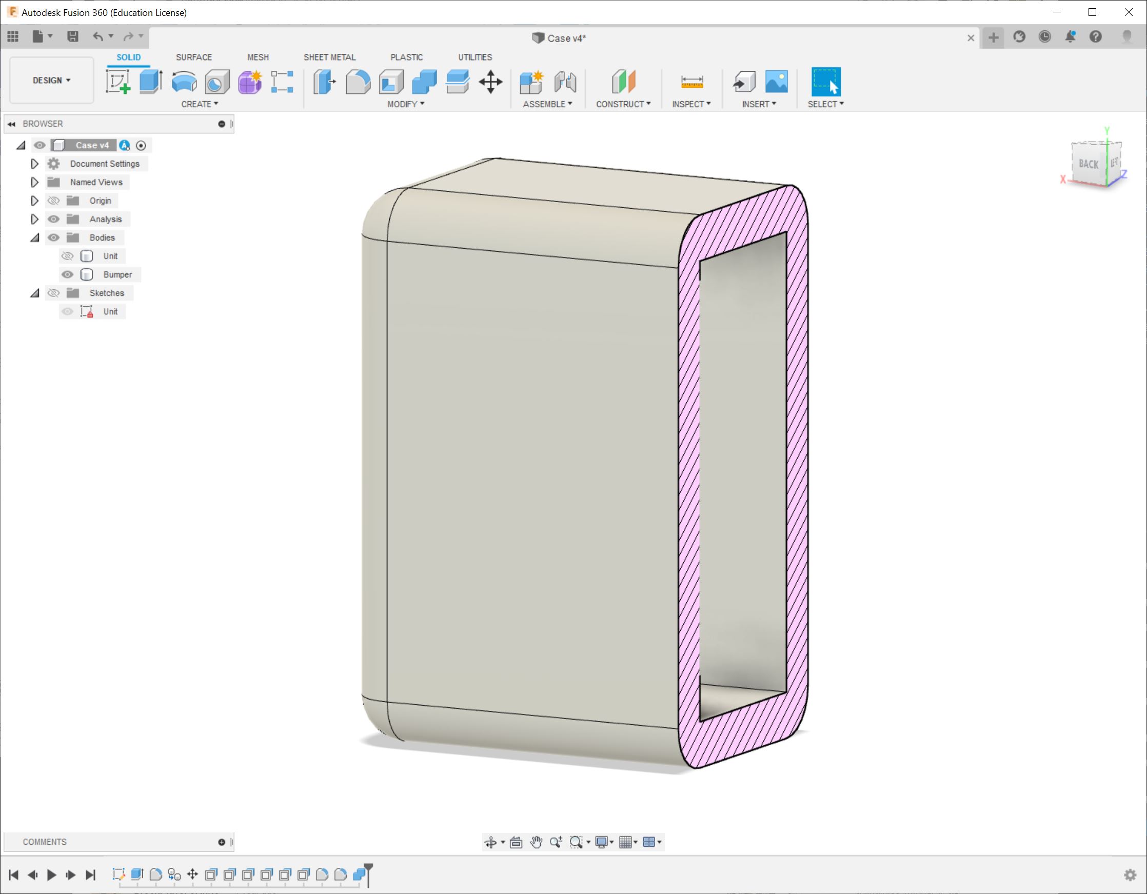
Using section analysis, we can look into the object to verify it is indeed hollow.
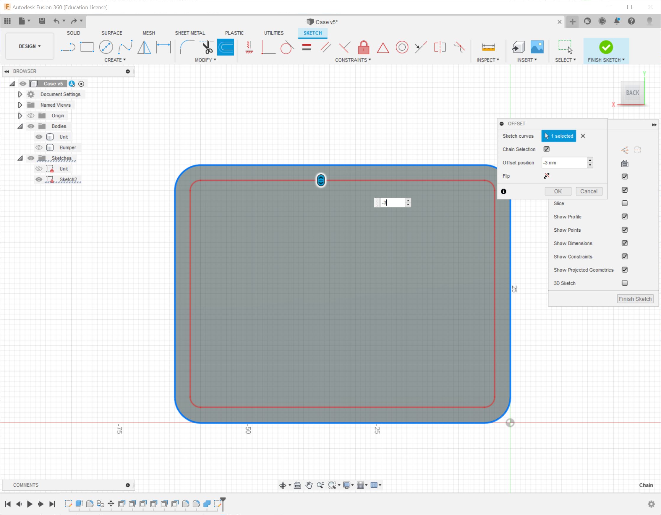
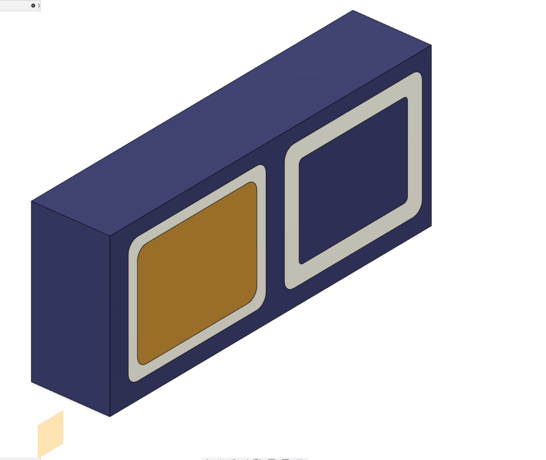
To create a the “window” part of the case, I add a negative offset to the object to extrude and cut through the case.
Now I extrude the inner part to create the “window”.
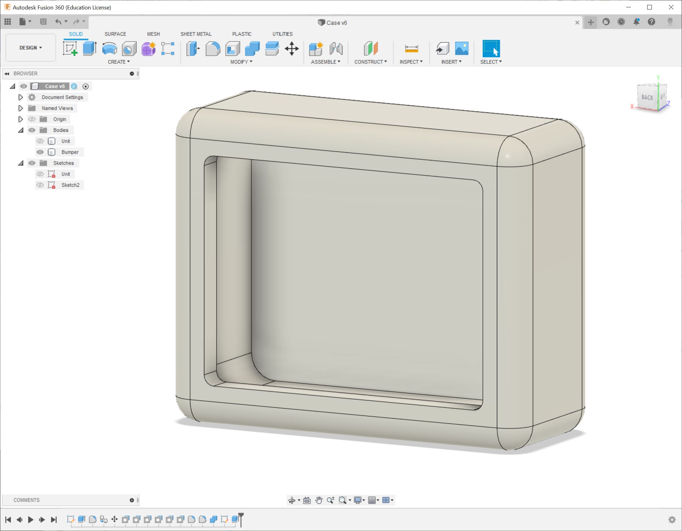
Then I just add a little flange to the outer window edge to make it all smooth and nice!
I will now call this a finished design of the case and move onto the next bit!
Unexpected wrench in the gears!
I was finishing up work to day, created a commit and pushed it to my repo. Moments later I got a email message informing me that my pipeline failed! It mentioned the specific commit and then checking out the CI-jobs:
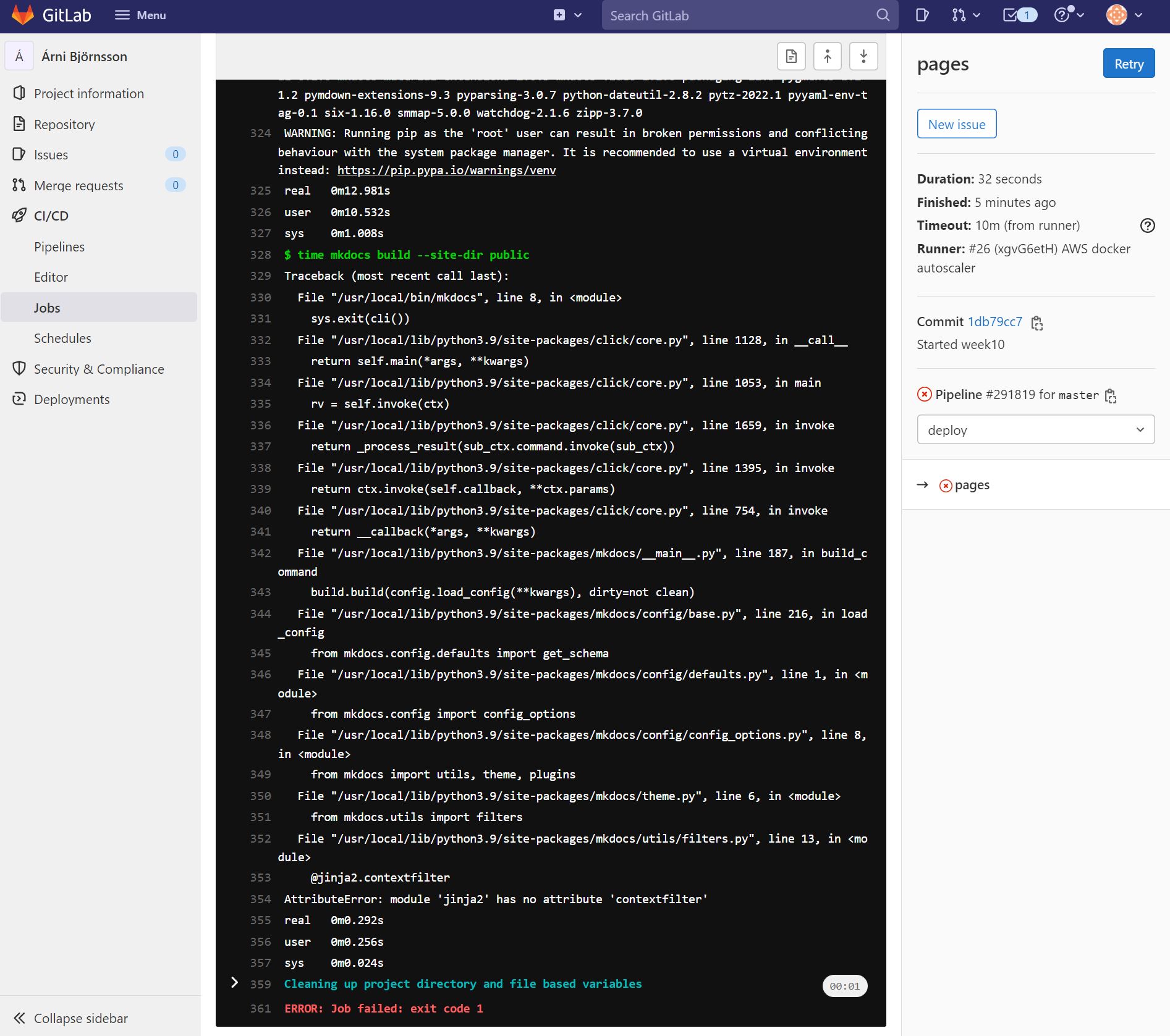
After verifying that I was not in the wrong here, I raised the issue on the Mattermost chat (only for students and Fab Academy staff, no link!).
The reason turned out that a package in the FabCloud system had been updated which broke the system. A few hours later I saw a notification from the team informing me that the makers had updated the system so I hope that when I push this commit, the pipeline will run successfully.
Update: This was indeed fixed a few hours later and the pipeline worked.
Here’s to pipelines and packages!
The mold
Well.... maybe I should have just cast a ball?!
Turns out you kind of need to scratch your head before making a cast. I admit I did not really spend a lot of time thinking about the whole process before I started, so now I needed to experiment a little. Fortunately, this experimentation takes place in the digital world only, so no material is wasted (if the conclusion makes sense!).
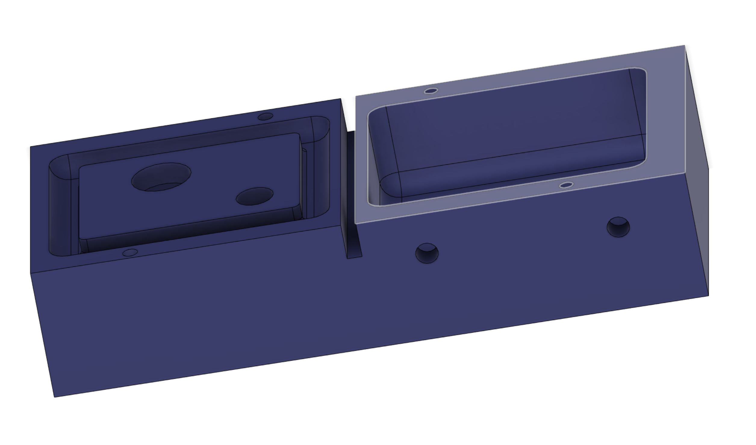
First thing I did, was to add a block representing the wax block I had with me. I then split the case into two parts, where the window/front part meets the sides and back.
I then moved and sunk the two pieces into the “wax” part.
Using the Combine function, I removed the material from the wax block.
This left me with the wax block and a cutout from it that I would use as a body to 3D print, mount to the other side and then cast!
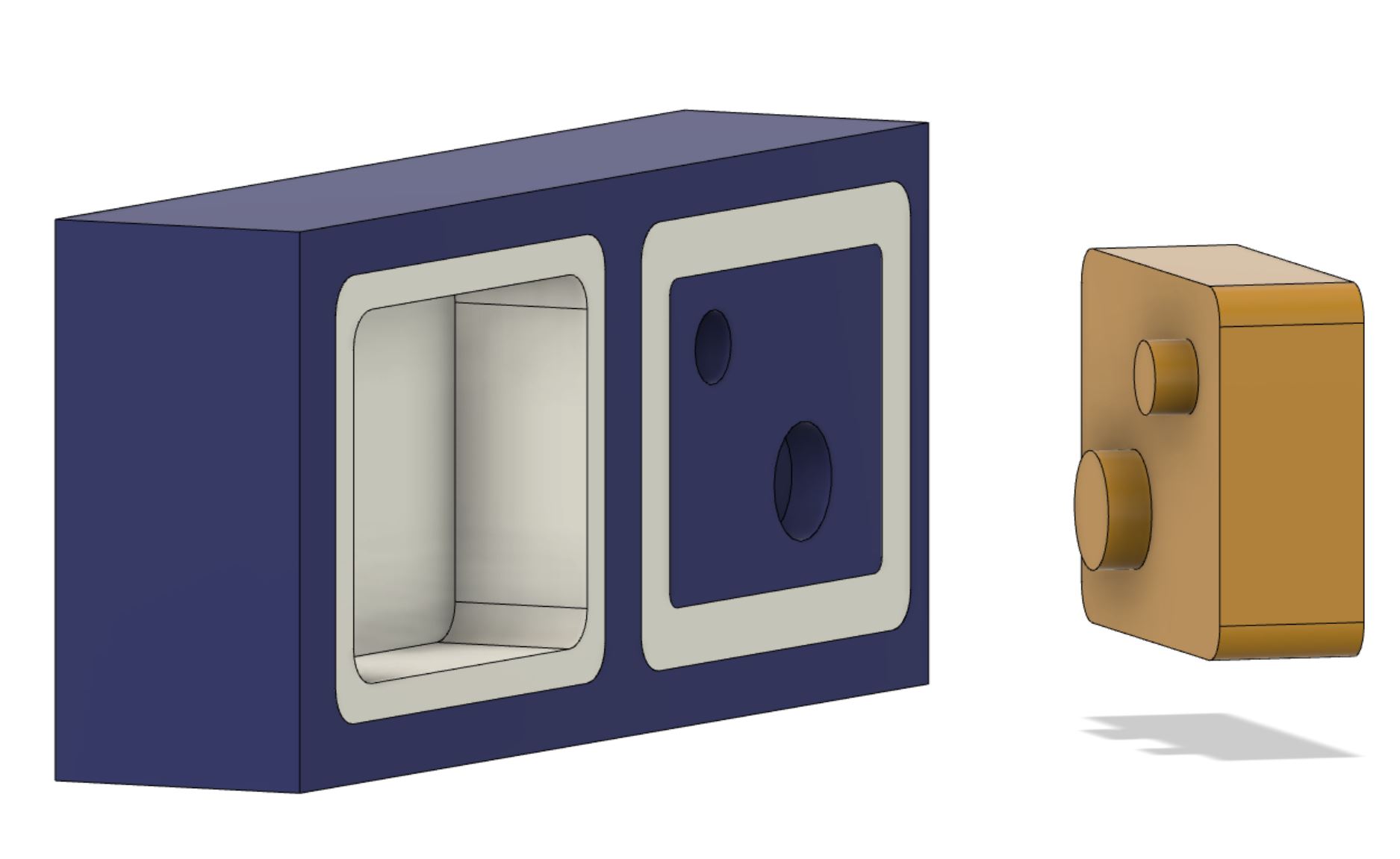
Here we see how the 3D printed piece should mount to top part. I just added a sketch on that face, added a couple of circles and then extruded/cut from them.
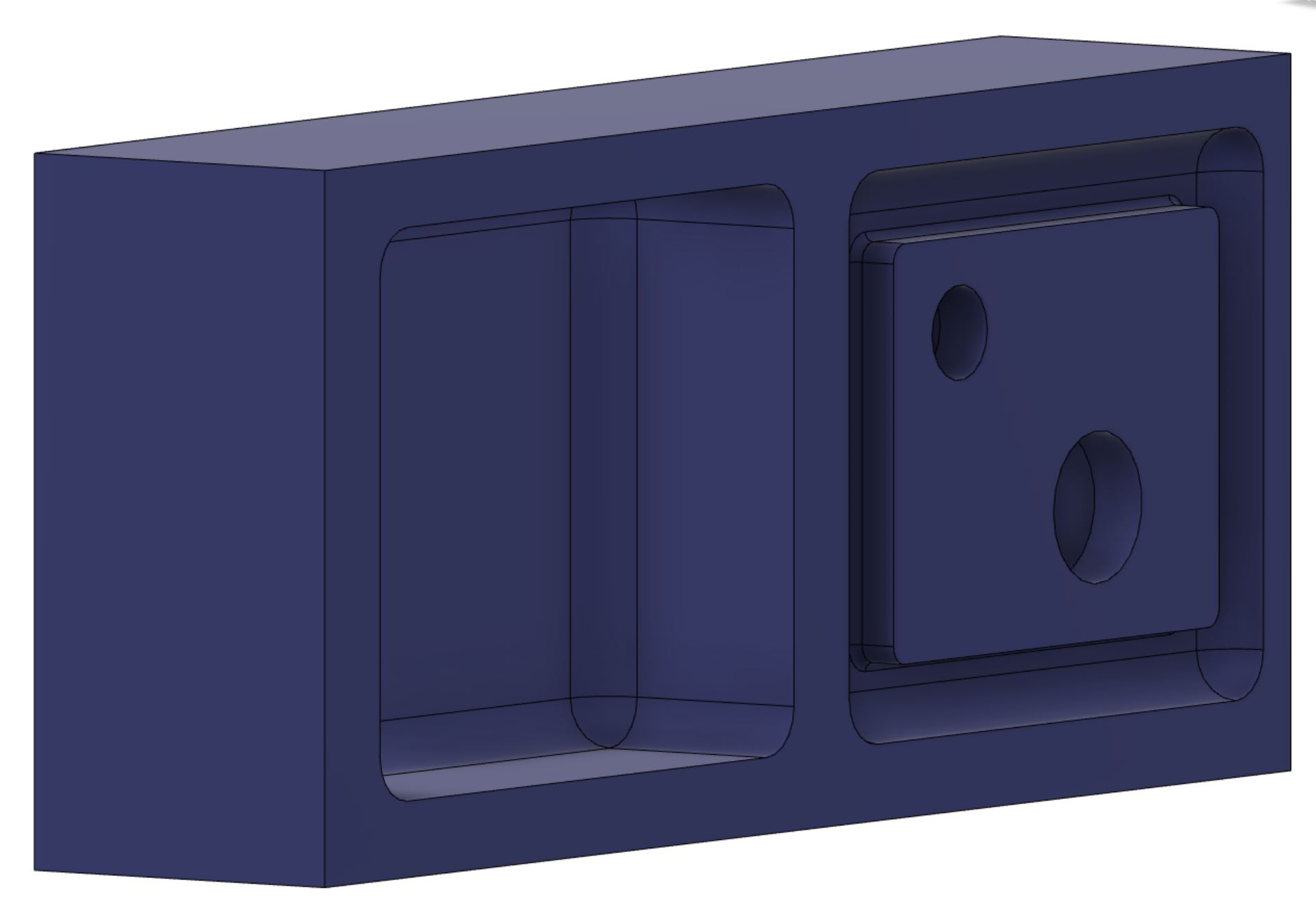
And a close up of how the wax looks without the case pieces and the one representing the to-be-hollowed-out-space piece.
Aligning the mold
As I plan to cut the mold in two, I need a way to center the two main pieces.
Using the same sketch as above, I created a center line between the two pieces. I then added a circles to one side, mirrored them and extruded into the material. I will then print cylinders in the same size, and use them as guides. They are 4mm wide and 5mm deep.
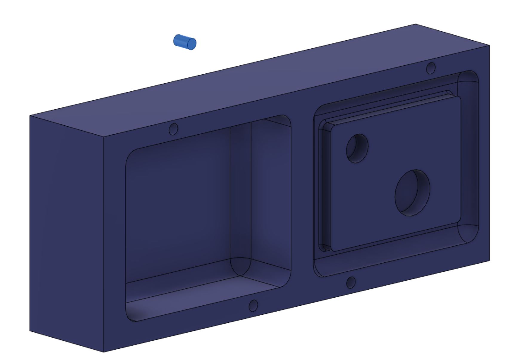
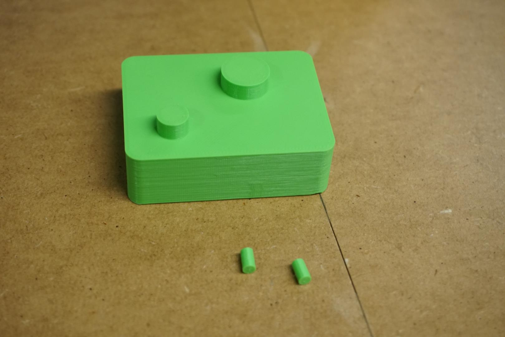
I then exported both the cylinder piece and the center-hollowing-body piece to be 3d printed.
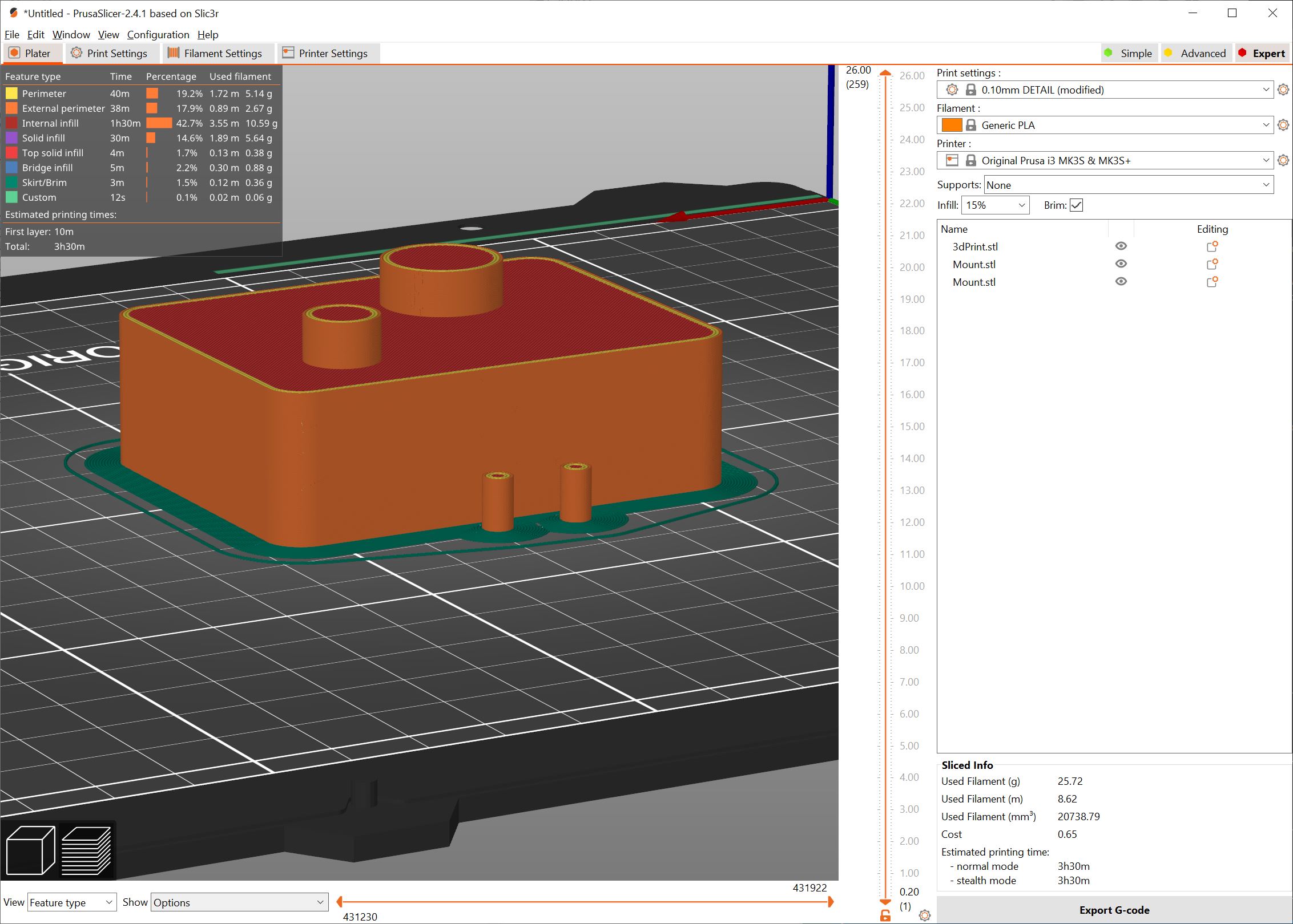
3D printing
I set the layer height to 0.10 mm, otherwise standard settings.
| 3D files |
|---|
| Cylinder |
| Body |
Manufacturing
Next up is the setup for milling the wax. Within Fusion, we now move from the Design tab to the Manufacturing tab.
First thing to do is to create a new Setup (Setup -> New setup).
Within the Setup dialog, you must set the orientation and origins.
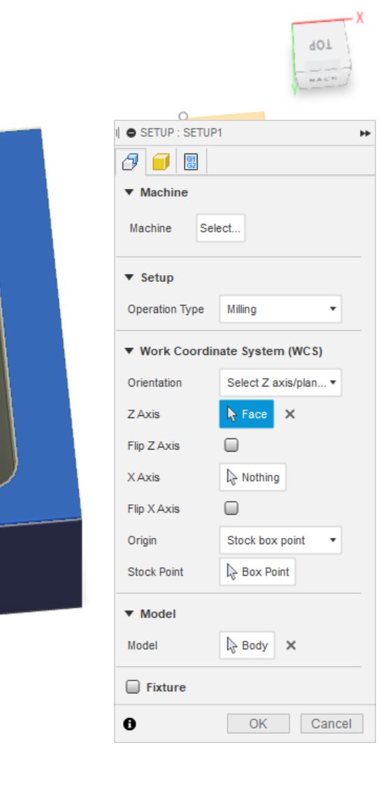
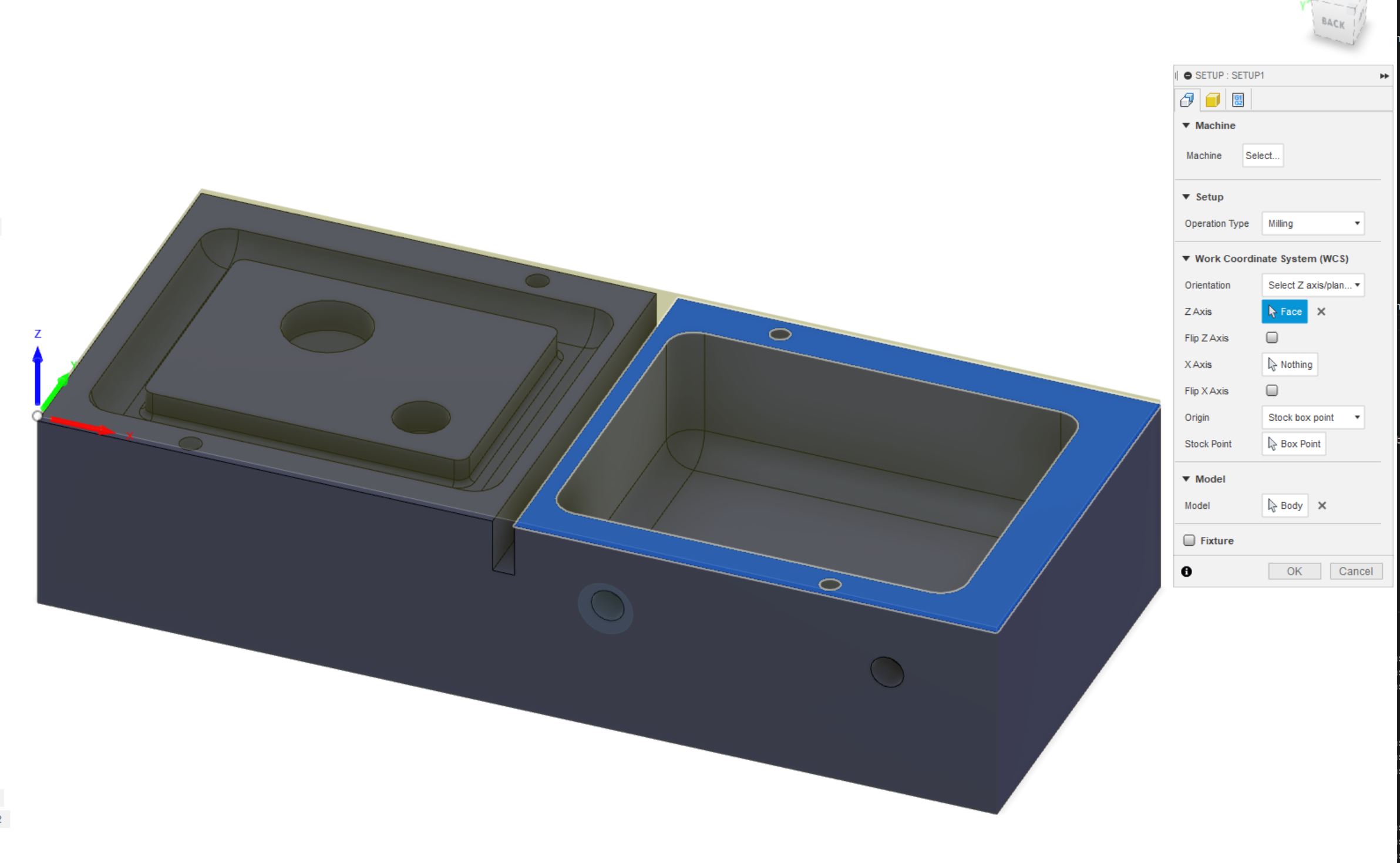
On the second image, you can see the X, Y and Z axis shown on the left corner nearer, facing us. They point from a corner “onto” the stock. The Z points “up” from the stock. This makes sense from the machines point of view, the lower left corner is the zero point.
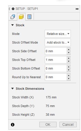
On this image, we set 1mm stock offset to the top to use for evening the surface. We have plenty of depth to work with, so it’s no trouble.
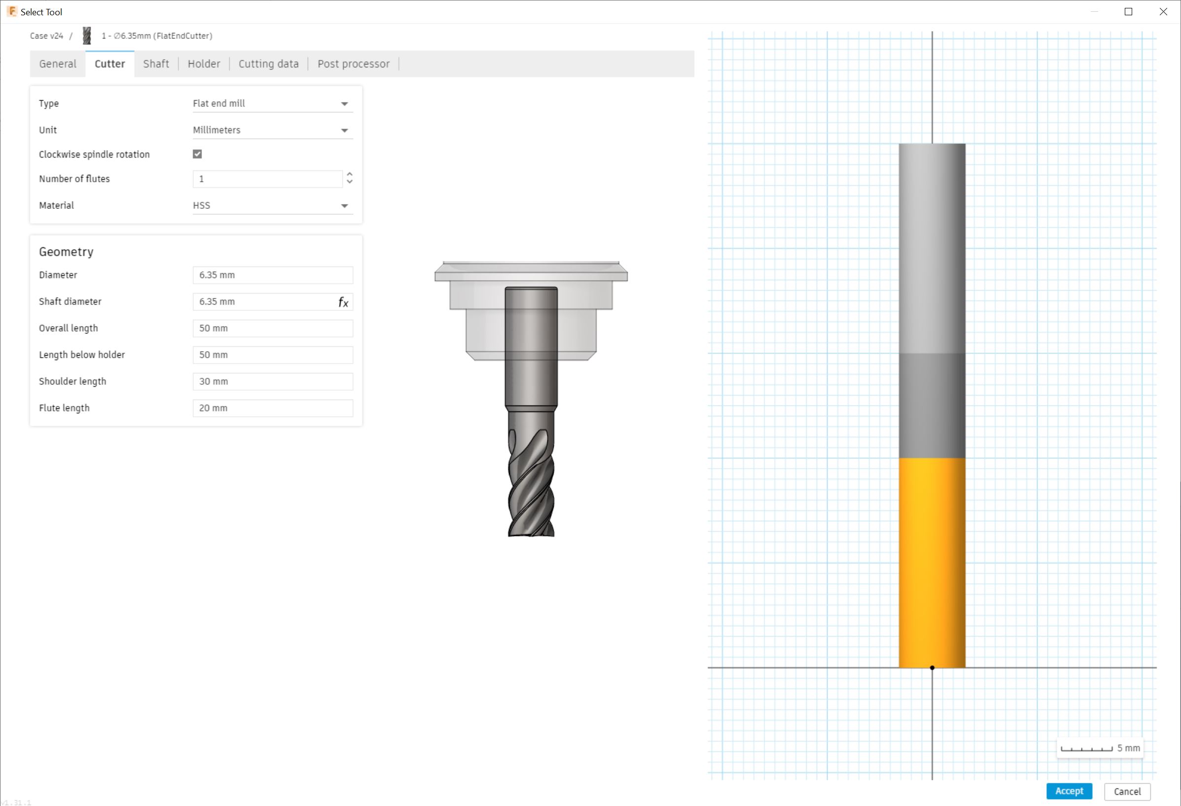
Next up, we add the tools we will be using.
First I planned to use two drill bits.
-
A single flute 6.35mm (1/4”) flat end mill, which would handle most of the material removal.
-
A ball nosed 6.35 mm bit for fillets (smooth edges).
Soon I realized I also needed a smaller flat bit for the small holes.
- A 3.175mm (1/8”) flat end mill for the small holes and the guide line for manual sawing once finished with milling.
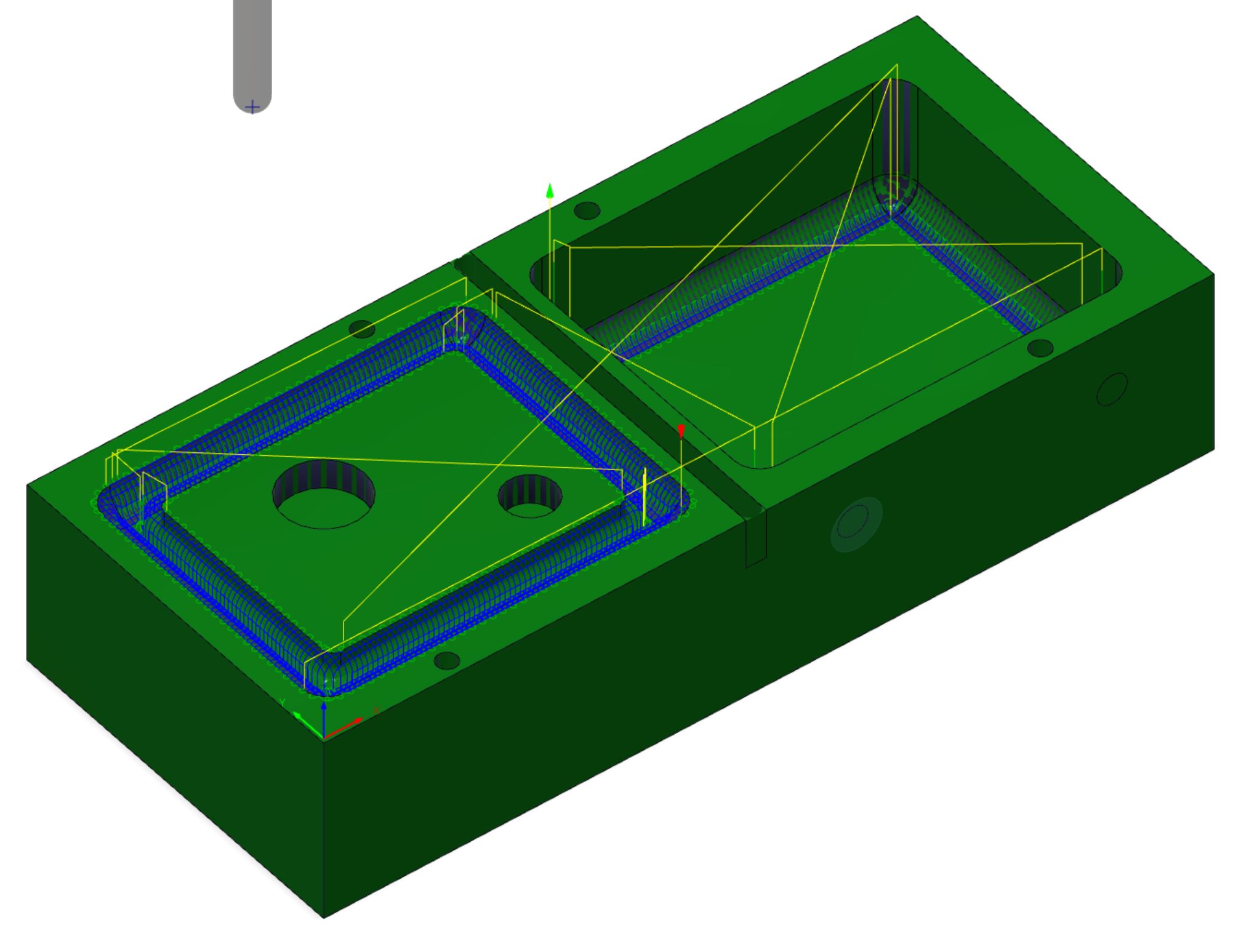
Toolpaths
I wound up creating 7 toolpaths! But before setting them up, I googled speeds and feeds for milling wax. I found these two sites:
It gives feed rates in inches per minute but I want them in mm per minute. For that conversion, I found this site:
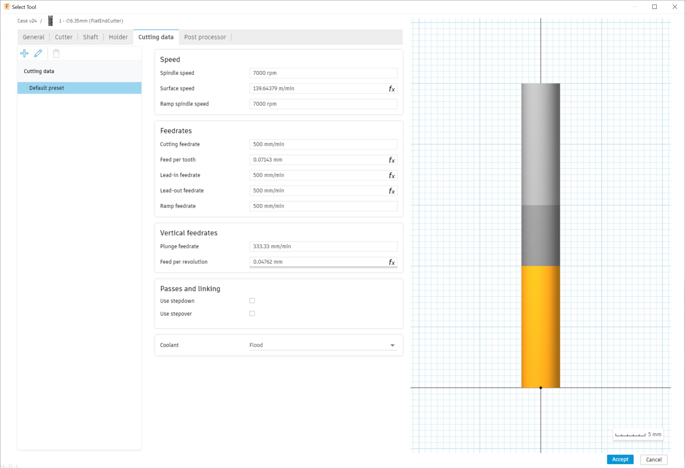
Quite nice info! So for my setup, I set the feed rates to:
Speed is around 7000rpm and feed is around 400mm/min, slight difference between 1/4” and 1/8” bits.
I may have overdone this part a bit, but it was a real nice opportunity to get comfortable with the machine and the various bits!
Let’s list the toolpaths out:
Face
First one is called Face in Fusion. It is meant to even out a surface of a material. The block was rather smooth, but this would be a smart thing to do since we need them to make good contact so the silicone will not leak.
Under 2D, select Face. A dialog will pop up. Select tool to use and set the specific tool to use. I set up the 1/4” flat end mill, which I can use again in this project.
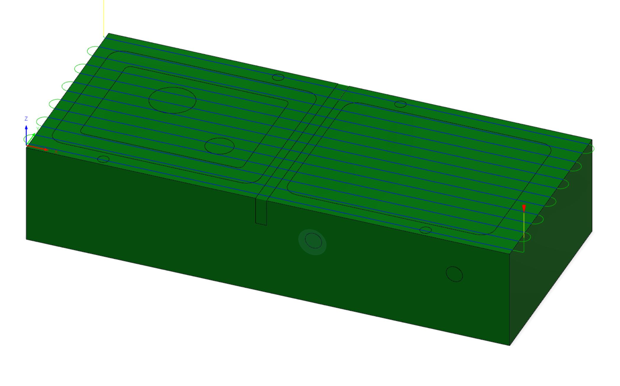
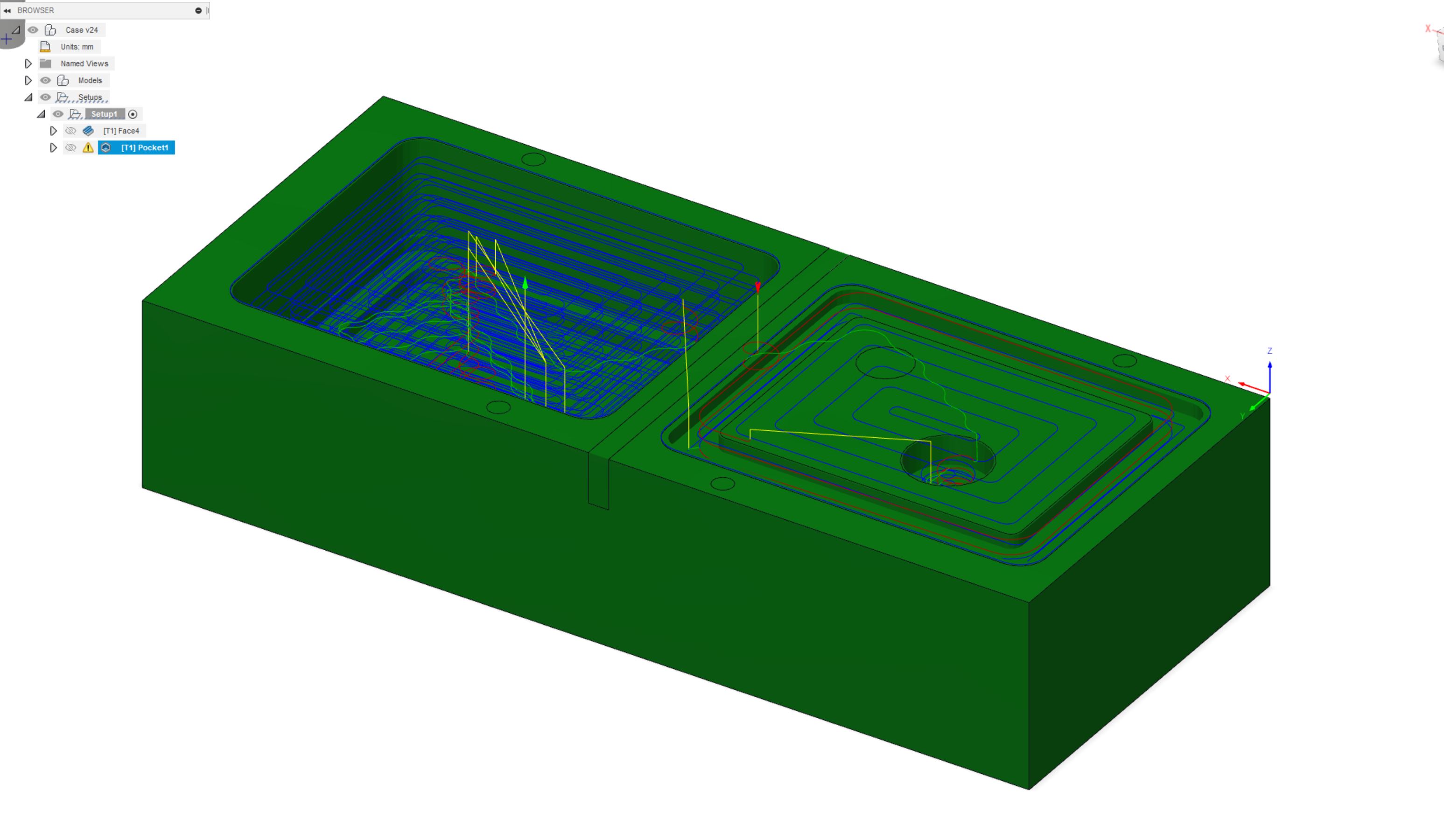
Pocket
Next, I created a Pocket toolpath. This is for material removal.
Under 2D, select “2D Pocket”. Use the same tool as above. The beauty here is that the settings for the bit transfer, so feeds and speeds are ready.
Selecting what needs to be cleared, we a presented with the result. I just noticed it later on that it skipped the smaller hole but it was of no fault, since it will be made later on.
It’s worth to mention now, that in the Passes menu of the toolpath dialog, you can adjust various settings, most notably the Stepover. It references how much the tool can step previous pass. In the same respect, Stepdown is how much the tool can step down into the material.
For this rough step, I used 3mm stepdown.
Contour
I added a contour toolpath, which was almost pointless but it just removes a bit of the material in the deeper part.
This is the last toolpath using this tool.
Flat
I added a flat toolpath, which is a finishing operation. For this operation, I used the smaller flat end mill, the 3.175mm (1/8”). The addition of the tool follows the same procedure as before.
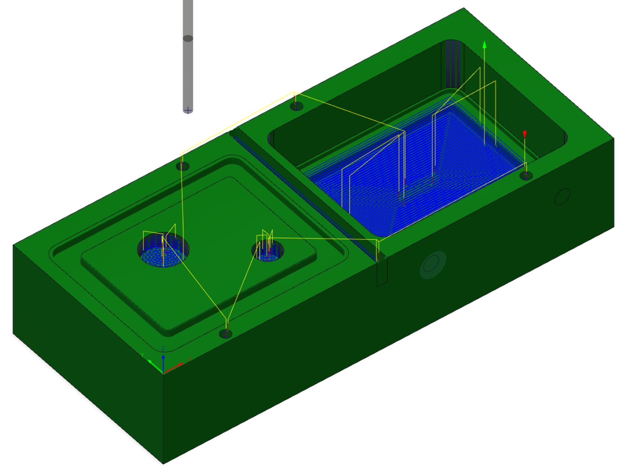
Parallel
Next up, I add the 6.35mm (1/4”) ball nosed bit, this is for the fillet parts.
You can create the Parallel toolpath by selecting 3D and then Parallel.
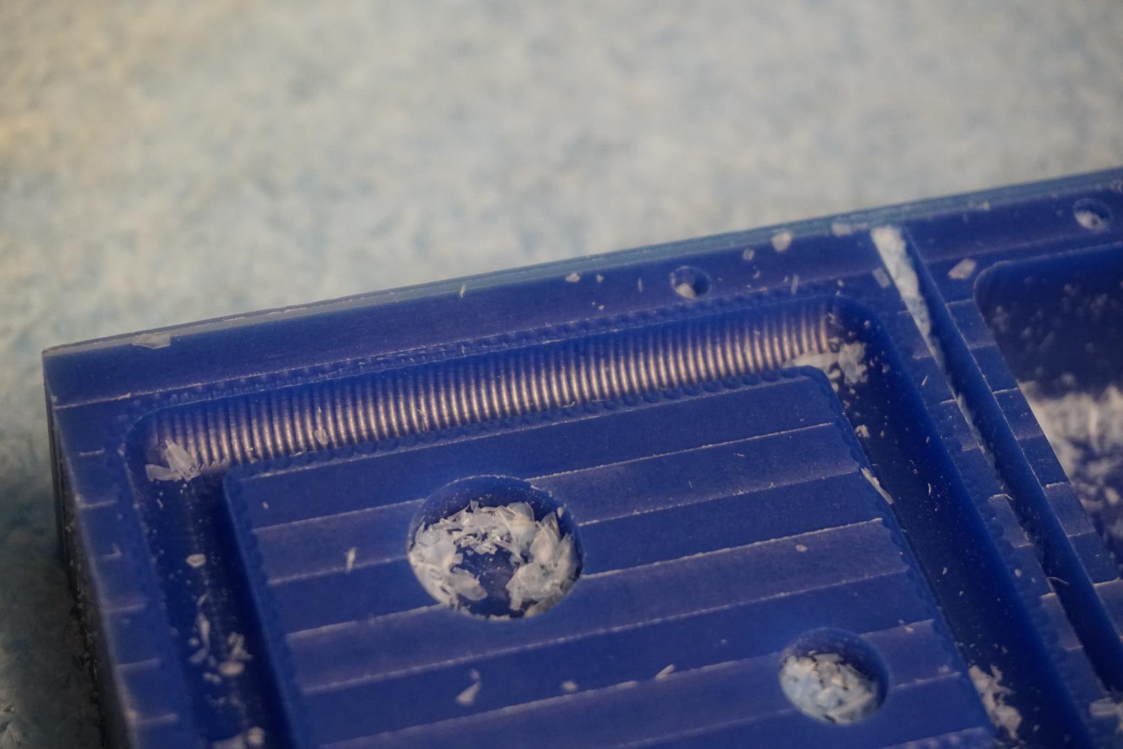
This is where I noticed I need to find a smaller ball nosed bit! If you look closer:
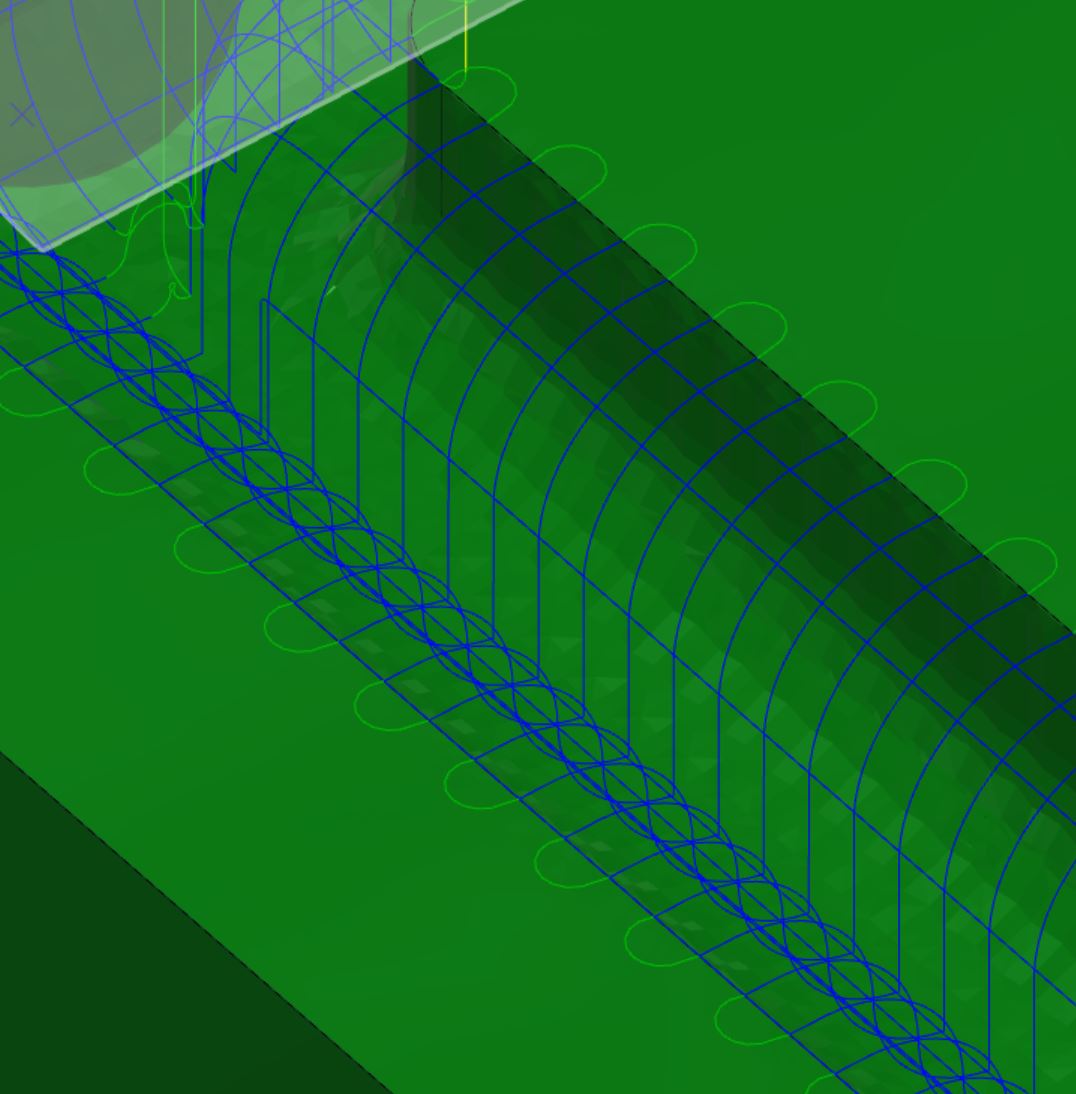
you see that the fillet in the bottom there is too small and the bit is not able to cut it.
I still add the toolpath using this one, as it is a fine exercise!
Another thing to note, in the toolpath dialog, is the Avoid/Touch surface option. This can be important for saving time! I used it here, but forgot about it in the next step!
Parallel - smaller bit
In the lab we found a smaller ball nosed bit, which is 3.175mm (1/8”). I add it to the toolpaths. This tool will require a collet change, as the stem is narrower.
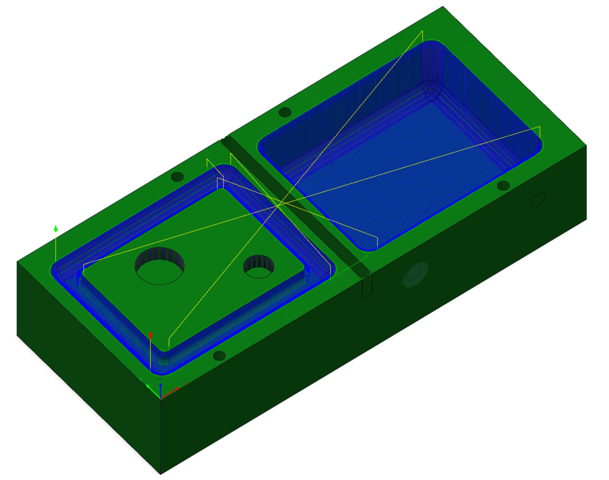
As you can see here, the large area in the bottom will be criss-crossed quite a bit! This is a bunch of time wasted, but I only figured this out after the fact.
When simulating the toolpaths, my eye caught a bit of roughness! This cannot stand!

This must be rectified!
Ramp
This is the last toolpath! I use the same tool as above, but this time I use the Ramp opertion. Ramp travels the Z axis in smoother way, that is the Z axis is constantly changeds. I thought this was a interesting operation to try and the simulation tells me that it should give me the desired result.

Ramp can be found under the 3D menu. I used the same tool as before.
Yet another thing to mention, is in the Linking tab in the tool dialog. There, you can for example set the angle of the ramping, which sets how fine (slow, low angle) or coarse (faster, higher angle) the ramping and therefore the final result is!
Once all the toolpaths are created, you go through them all, right clicking and select Post Process. Within the dialog, all I had to do was to select the Roland ISO Post profile and select my output folder, and hit Post.
| Toolpaths |
|---|
| Face |
| Contour |
| Flat |
| Parallel |
| Parallel - smaller bit |
| Ramp |
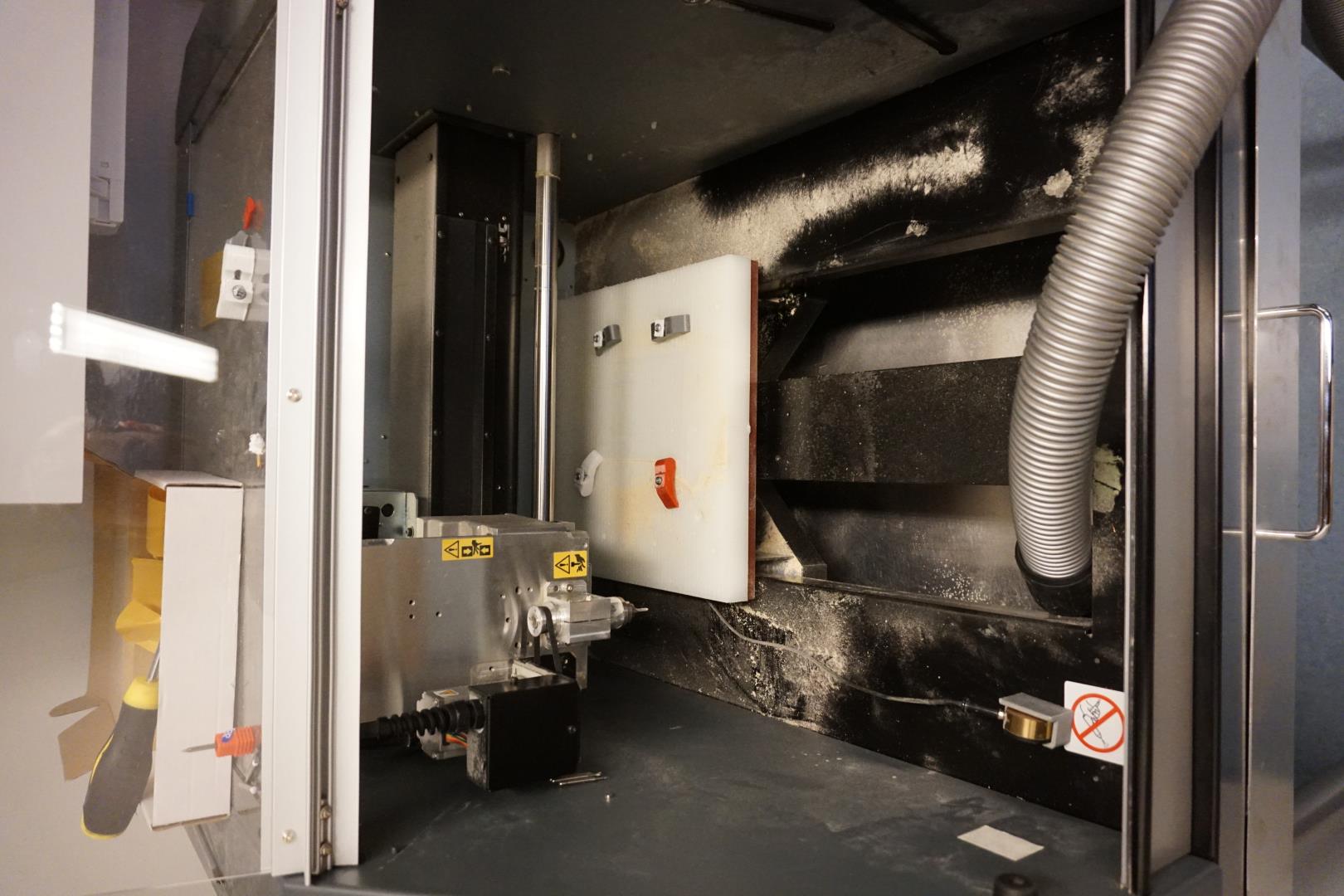
Milling
Now, onto the physical stuff!
Prep!
First of all, clean the Roland machine! This is not just my cleanliness but also my material saving method! By properly cleaning the machine of older materials, such as from milling PCB boards, the wax shavings can be used again!
This makes the earth happy!
Drills
These are the bits I started out with:
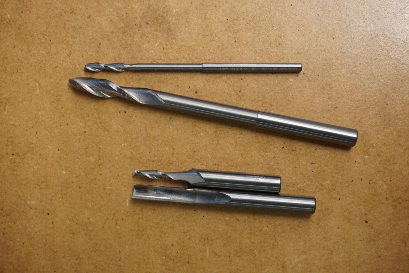
There would be a small hickup with one of those, but more on that later.
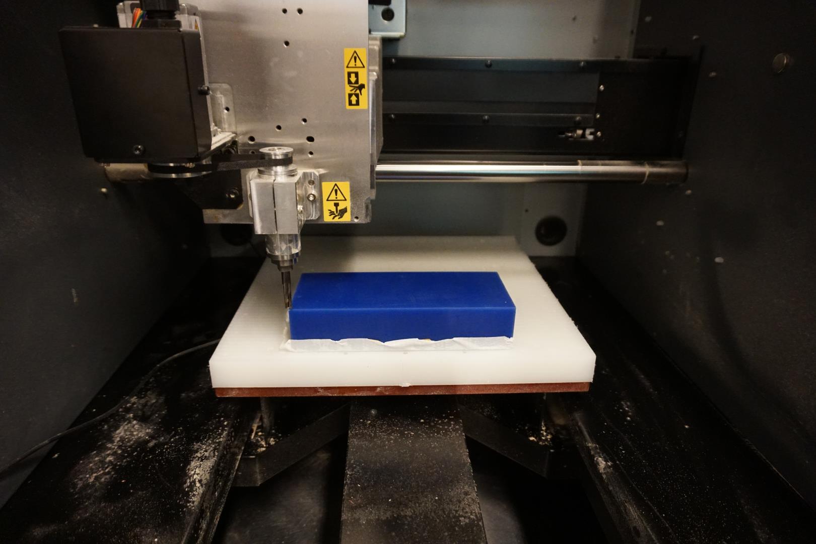
Mounting stock and first bit
Using carpet tape, I mounted the wax stock to the plate.
I made a mistake here, mounting the stock flush to the edge of the plate. This resulted in I could not properly set the zero point, which means I would waste material and just did not have it available. Too much deviation from the design would mean I would mill outside of the stock.
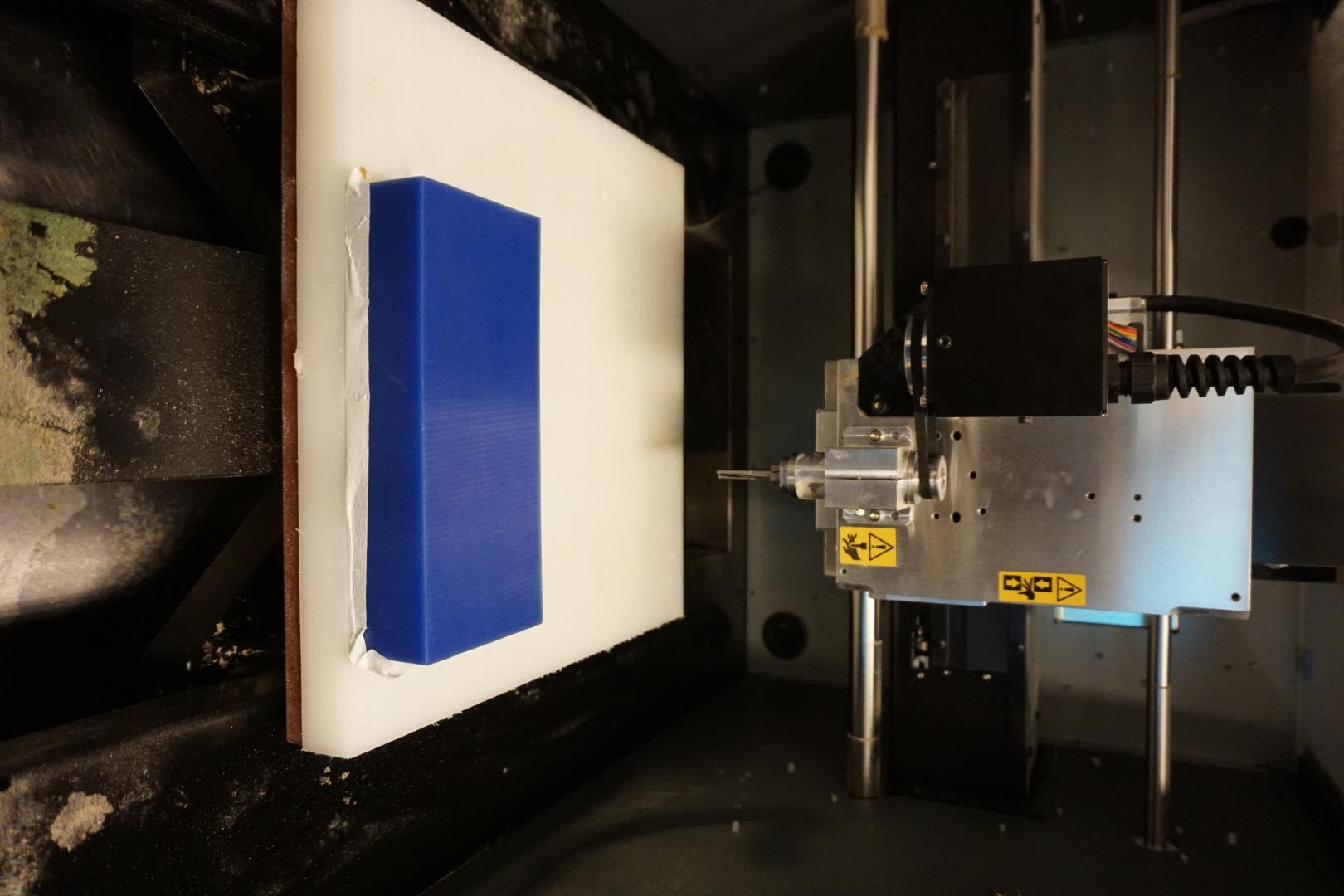
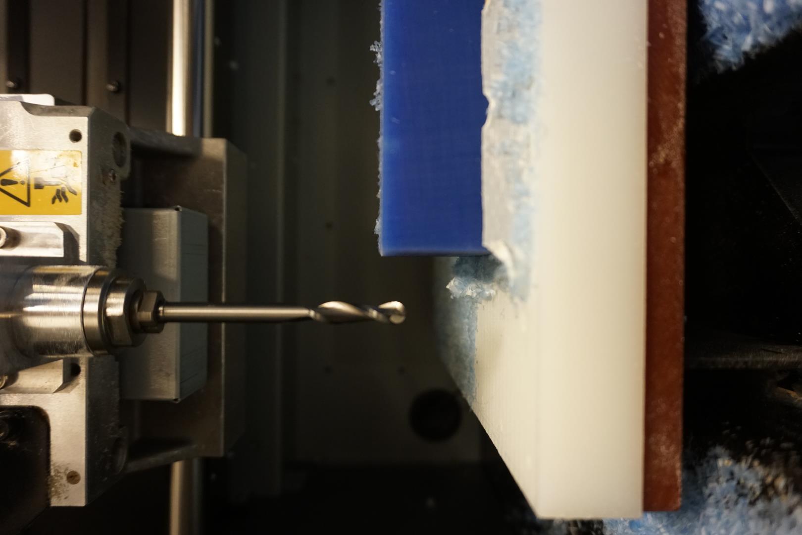
After removing the wax and positioning it properly, I added the first bit.
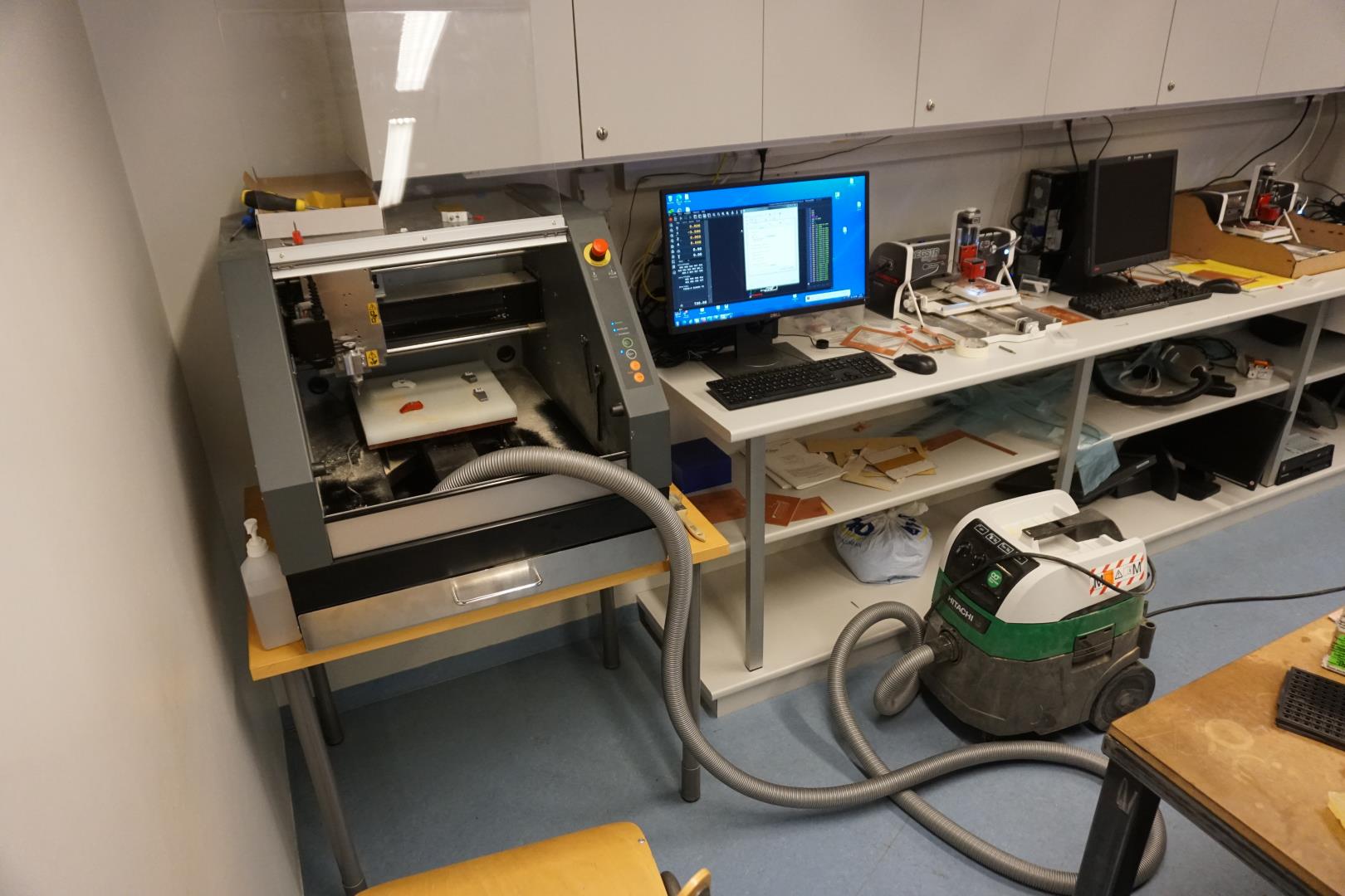
Adjusting the Roland
Here we see the interface of the Roland machine, the program is called VPanel.
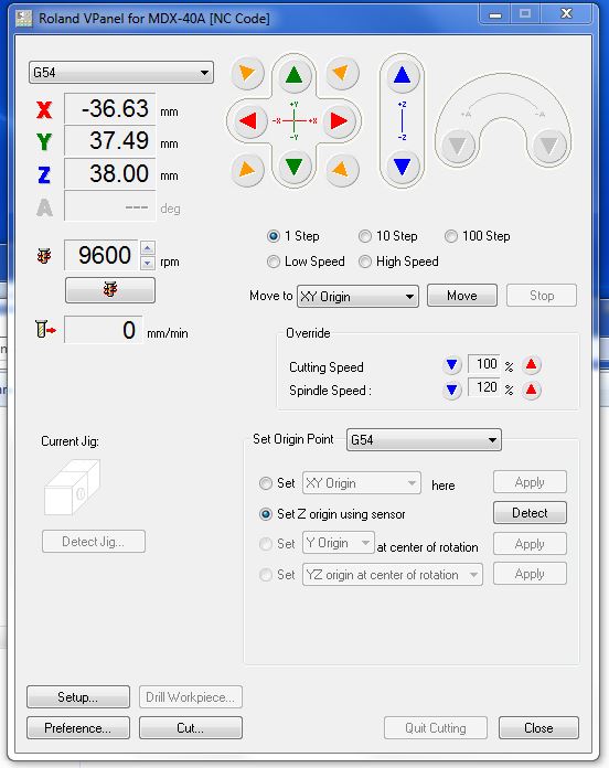
You can manually move the router manually and in various steps/speeds. This very handy, as the highspeed is quite fast and you can go all the way down to a single step per click.
I move the router so the center of the drill bit is centered to the lower left corner of the stock. That is the X,Y zero point! (pictured above)
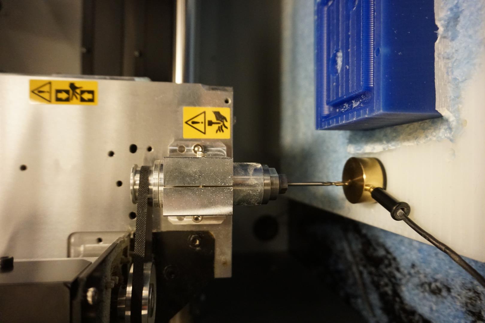
Next is to set the zero point of the z axis.
The mill includes a auto heigh function within the program. I select the Set Z origin using sensor option and position the sensor on top of the stock. It works by sensing the height of the sensor and the program the subtracts the height of the sensor from it’s current height, thus finding the exact zero point.
A bit of trouble!
This resulted in a bit of trouble for me. When I had to change the tool, I had lost the height reference! What I did was to set the height with the automatic sensing, but on the plate below the stock.
Then looking at the height of the stock within the fusion design, which was 38mm, I manually adjusted the height to 38mm and selected Set z origin here from the dropdown menu! This worked perfectly.
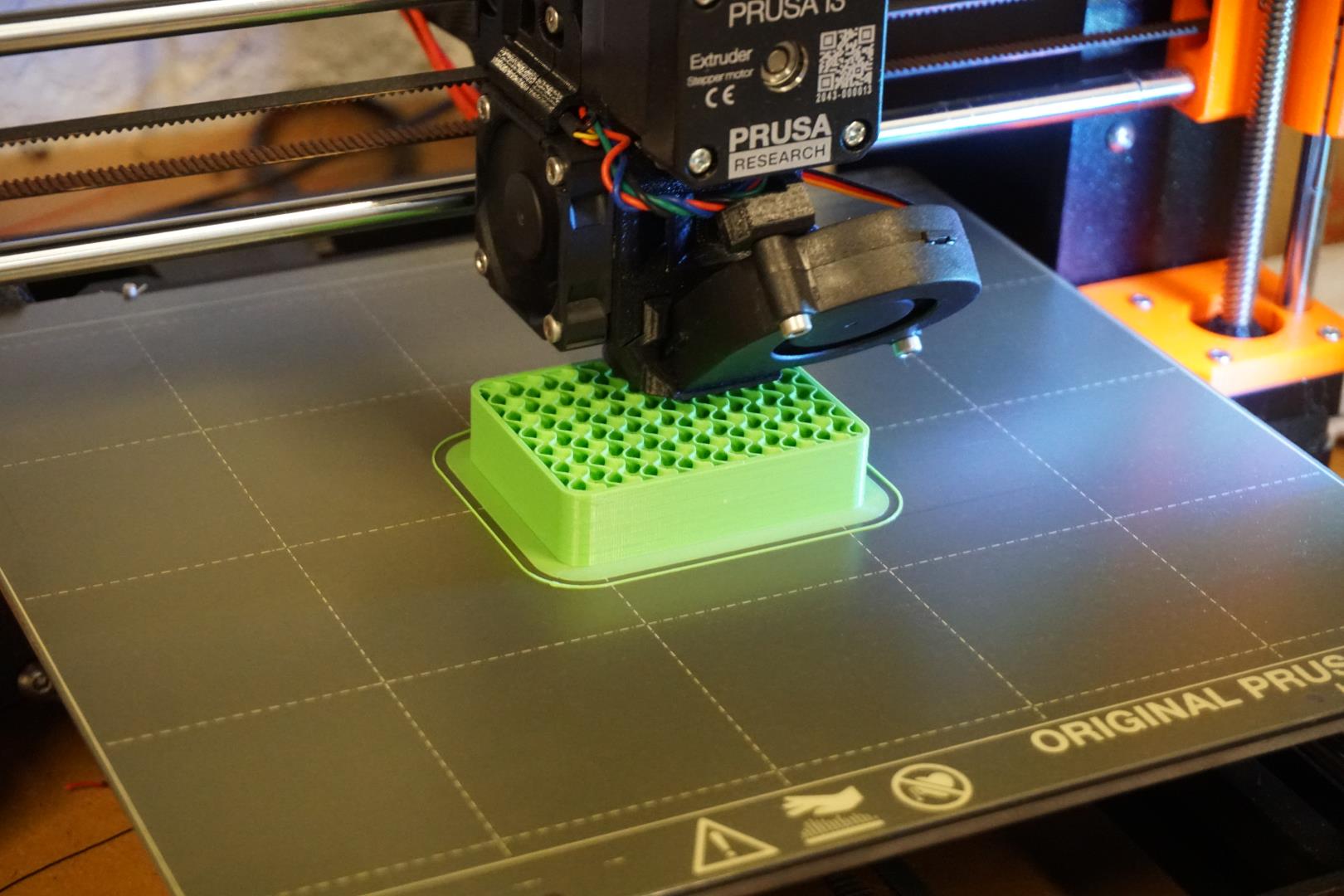
Milling the stock!
I then loaded the first toolpath, using the Cut... option and started milling!
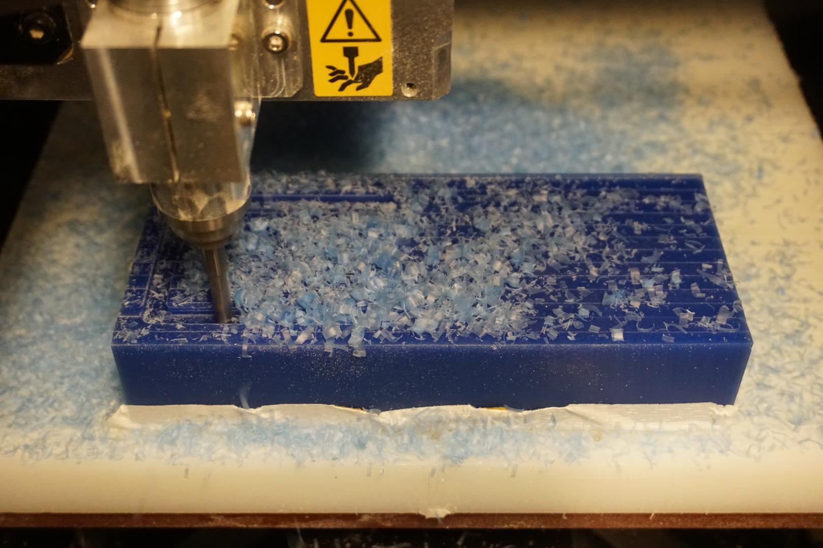
The one flute bit can sound a bit rough, so playing with the cutting and spindle speed within the program can help making it “sound right”. It was actually a quite nice experience to get it sounding perfect!
The milling went fine with the first bit and the shavings looked very good. No melting of the wax or jamming in the bits. Great success!
More trouble!
After finishing the first three paths, using the first bit, I started the first tool change. After realizing how I could solve the height issue mentioned above, I changed the tool to the second bit. Then I ran into the second issue! The bit was too long!
My trusty colleague found another bit, a metric one. The stem was shorter and it was 6mm but with the same shape, so I could use it. All I had to do was to adjust the tool within Fusion and “post process” it again to generate a new NC file.
Continue milling!
After figuring this out, I finished the rest of the milling. It went very well, all the shaving looked good and but it did take a bit of time. As mentioned before, I probably over did it a bit but we all know:
There is no kill like overkill!
or maybe…
There is no mill like overmill!
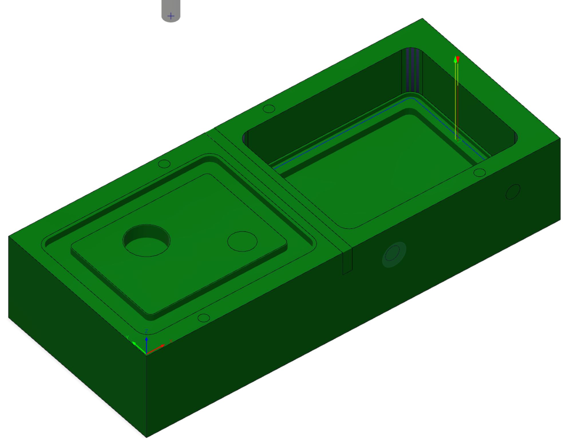
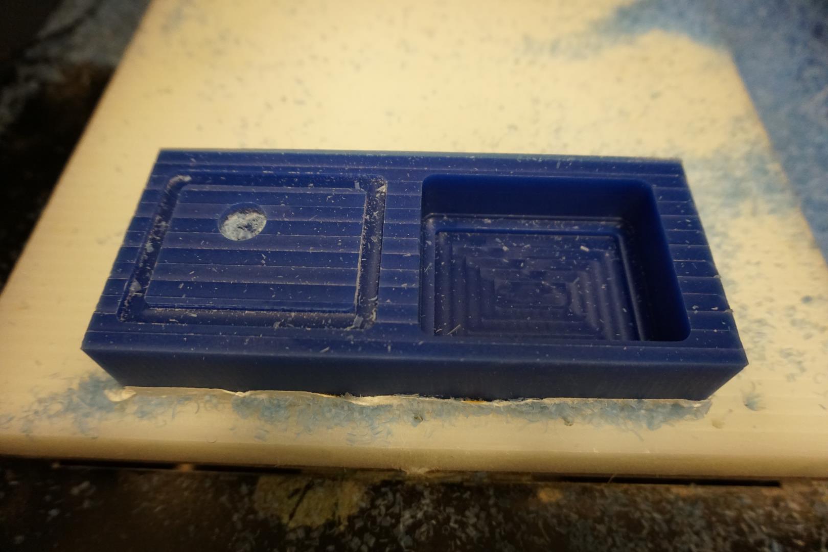
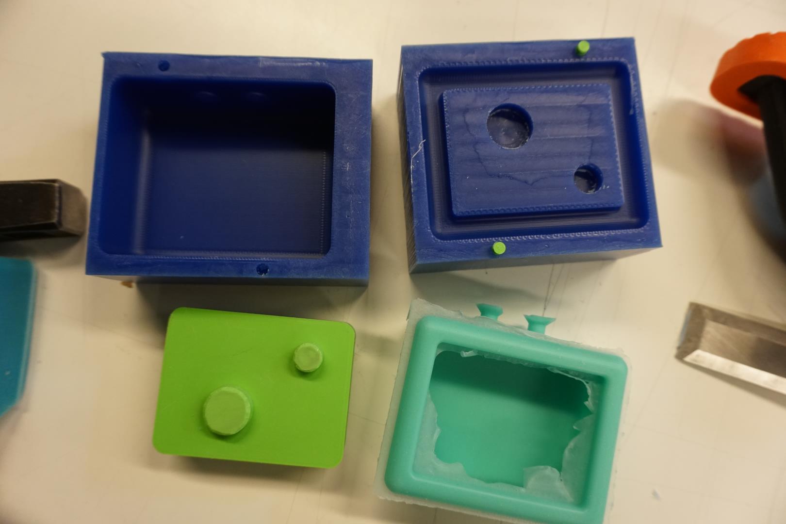
After finishing with all the paths, this is the result!
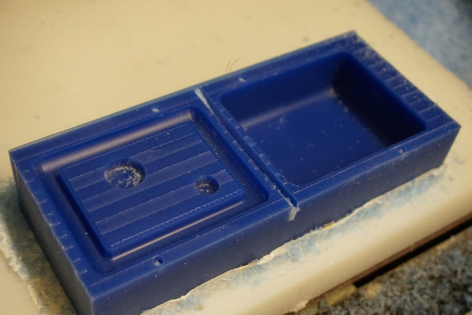
Touching the part, it’s quite nice!
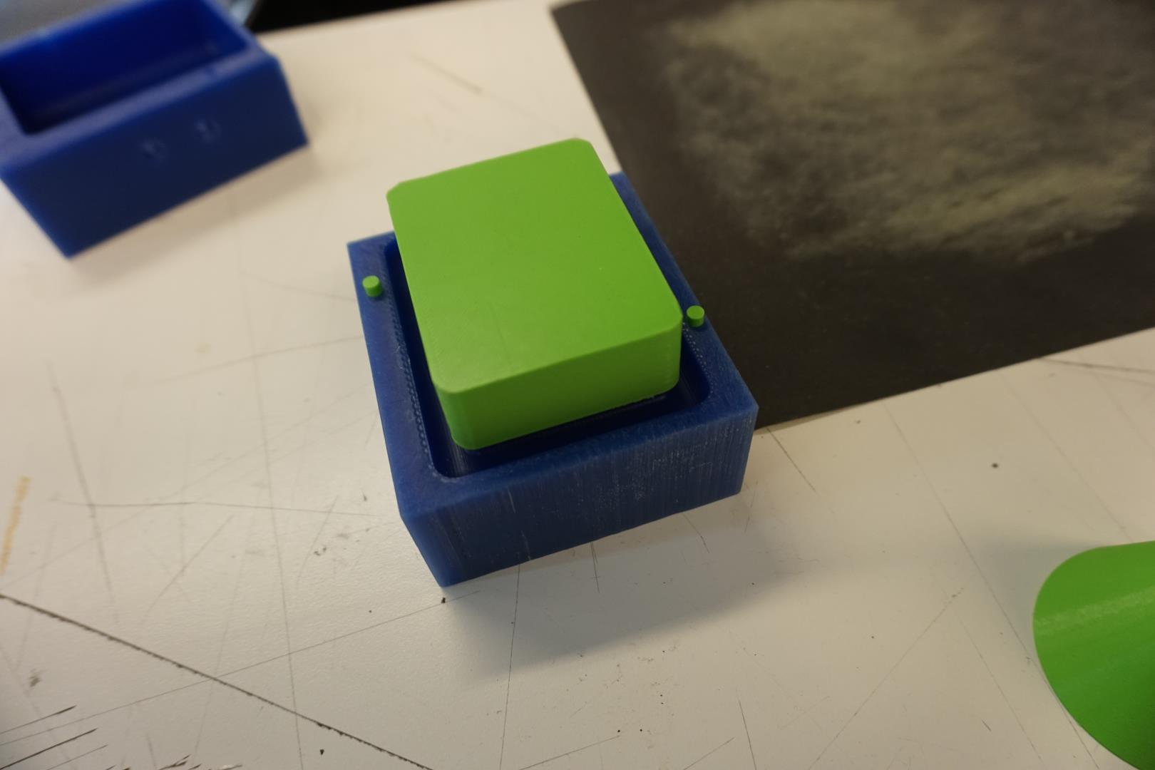
Before removing the part from the plate, I decided to test fit the 3D printed parts.
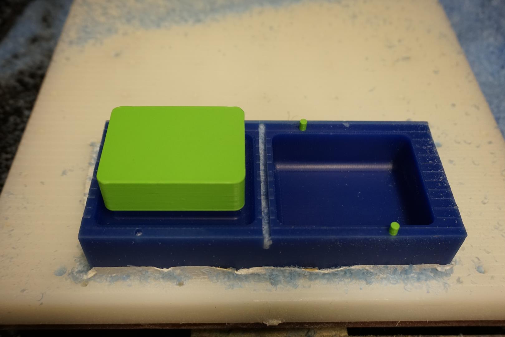
They seem fit quit snugly, I did not put much pressure on them.
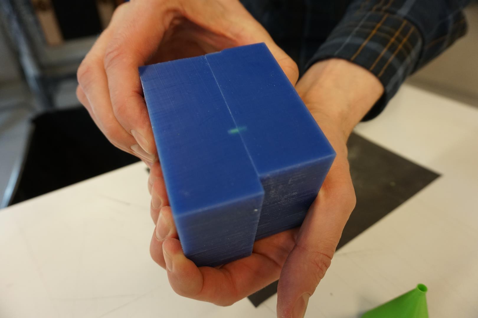
Next phase
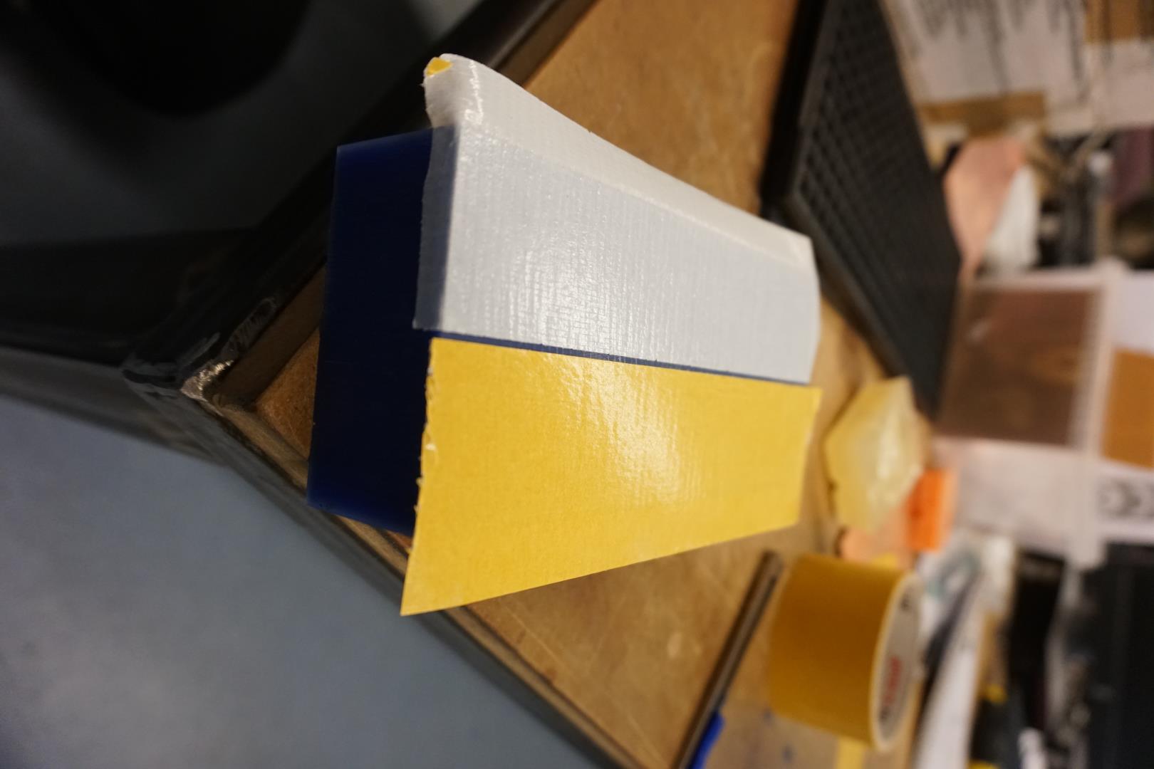
I removed the part and cut it in two. I then inspected them and ever so lightly sanded the faces that would touch.
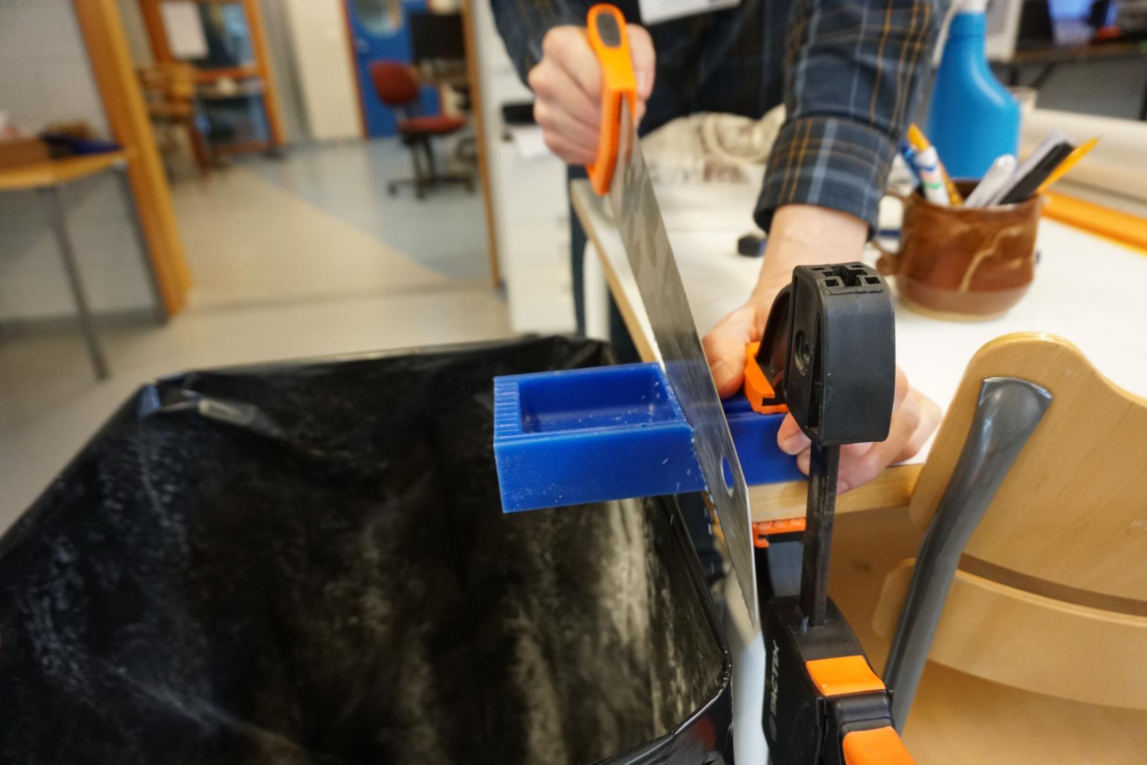
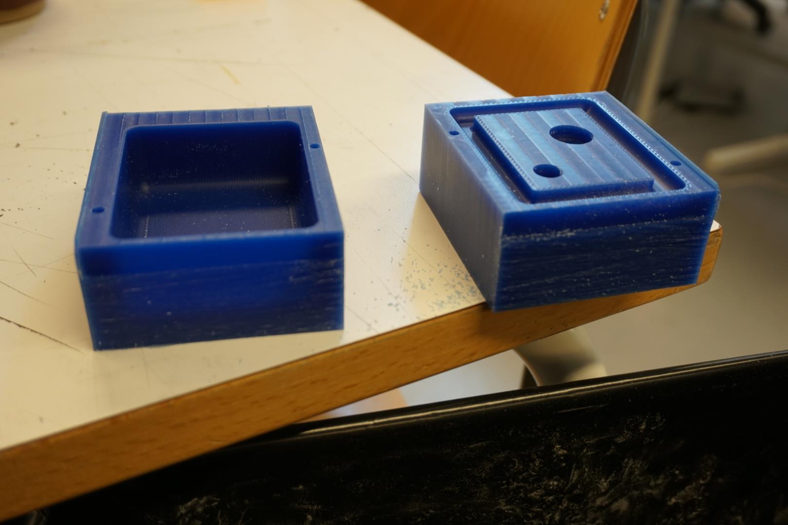
There was a slight edge left, which was easily removed.
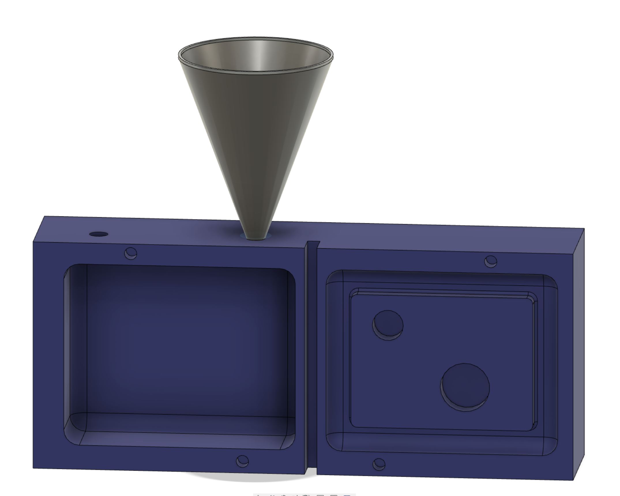
Inlet for pouring and a funnel
Last thing to do, is to decide where to pour inn the silicone once all parts are complete and mounted! I actually did this while the milling took place, but for the sake of nicer reading, I’ll document it here! =)
In Fusion, I added two 6mm holes on the “side”.
I could have done this on the mill, by just milling out parts of the edge but I found it cleaner to do it manually later on.
One hole is meant for pouring in and the other one is for venting the air out, so I could use a funnel to pour the silicone in and minimize risk of air pockets.
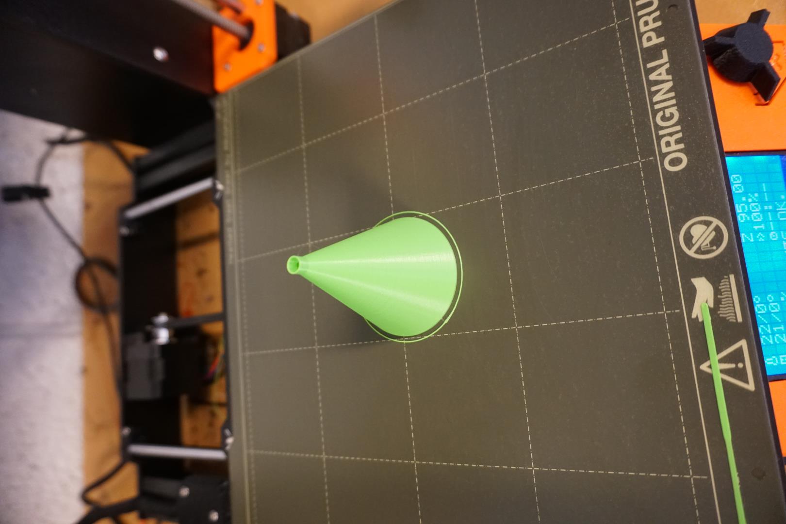
I quickly sketched up a funnel and started the 3D print job, using the Spiral vase setting within Prusa Slicer.
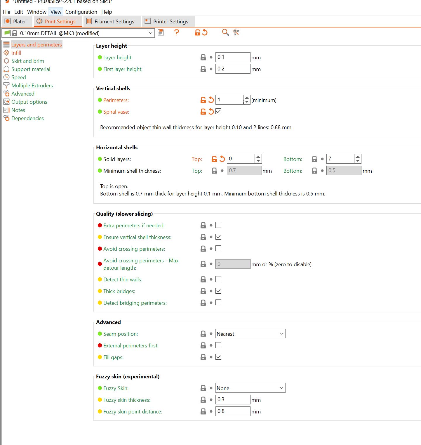
It is a nice feature of the program, allowing you to print certain model in a continuous way with very thin walls. The print job was quite successful!
| 3D print file |
|---|
| Funnel |
Next up, drill the two holes!
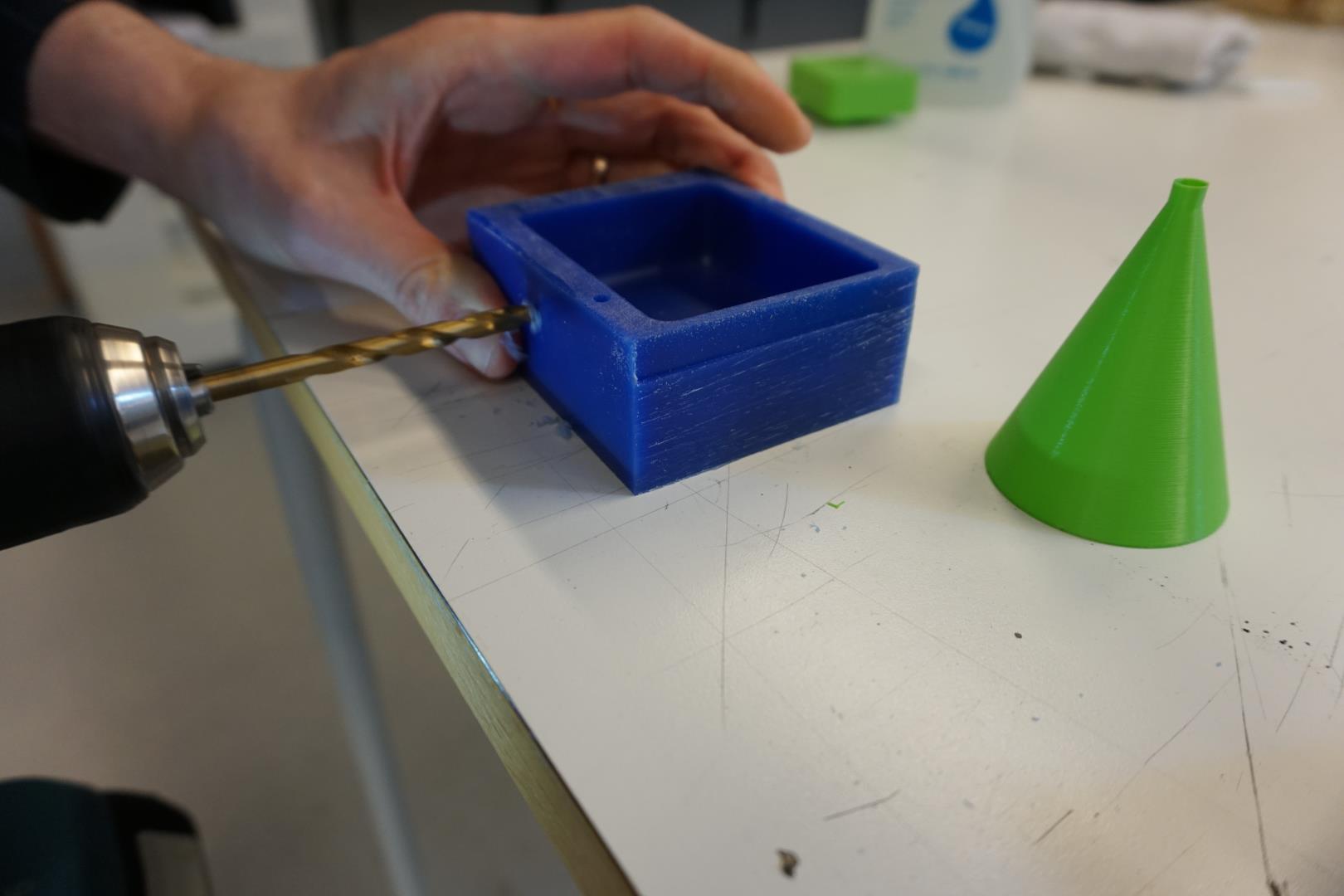
Putting it all together!
Fitting the mold
After cleaning the mold and all the pieces well and test fitting more, I found that I needed to adjust the 3D printed piece a little bit,by hand. It was just a tad bit too tight, as I had not really put any clearance in the design. Using a bit of sanding paper and a small knife, I adjusted the two protruding cylinders of the piece and then it fit quite snugly!
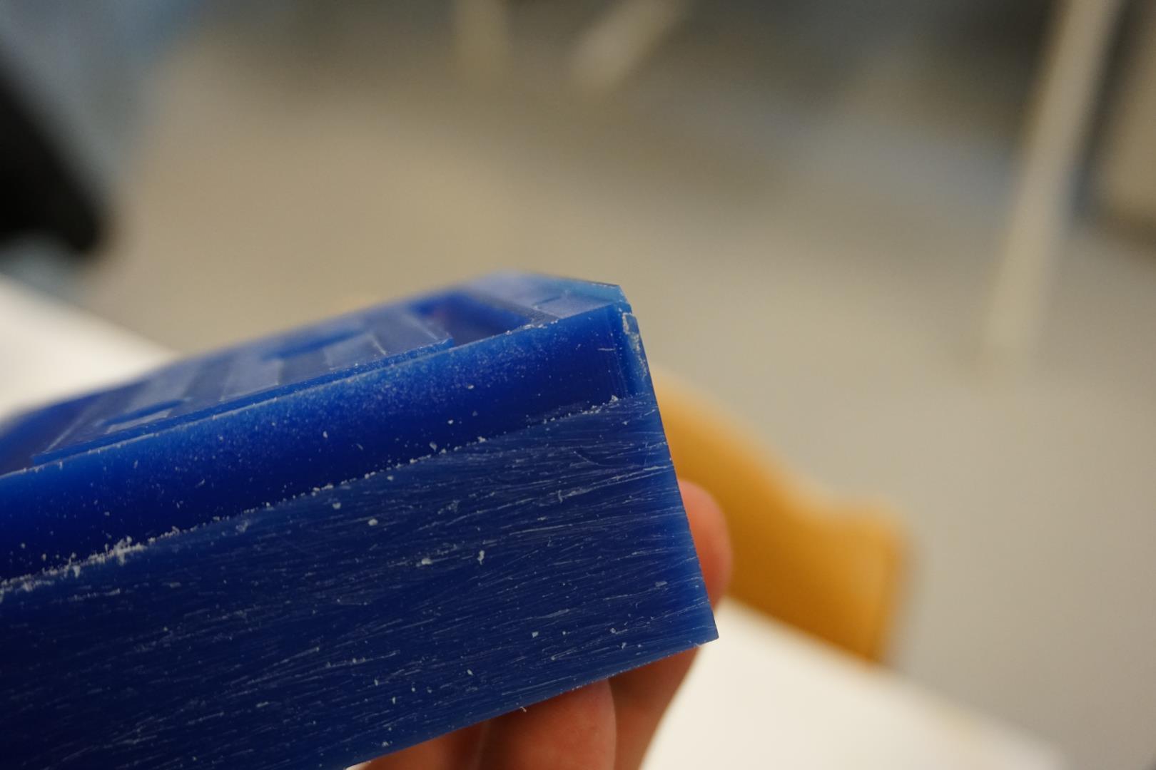
Here we can see how thin the wax on the side is. But it held well.
Now is a good time to mentioned a concern of my dear instructor, or a tip he gave me, when we spoke and I shared my design and with him.
As I had planned to pour the silicone into the side of the mold, rather then the top, we was worried about the silicone leaking. And the concern is valid! My design has the mating surfaces vertical while having them horizontal and near the top would be ideal.
But I simply must find a good wall to hit my head once in a while and I thought this would make a fine specimen of such a wall!
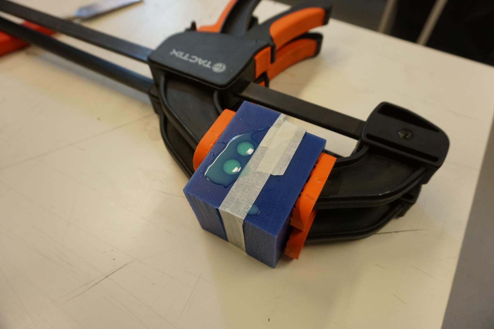
Casting #1
As stated at top of this site, I had planned to use the SLOW cure version of the silicone. But in a last minute decision, I and my helper decided to use the fast cure version. This was NOT the best idea!
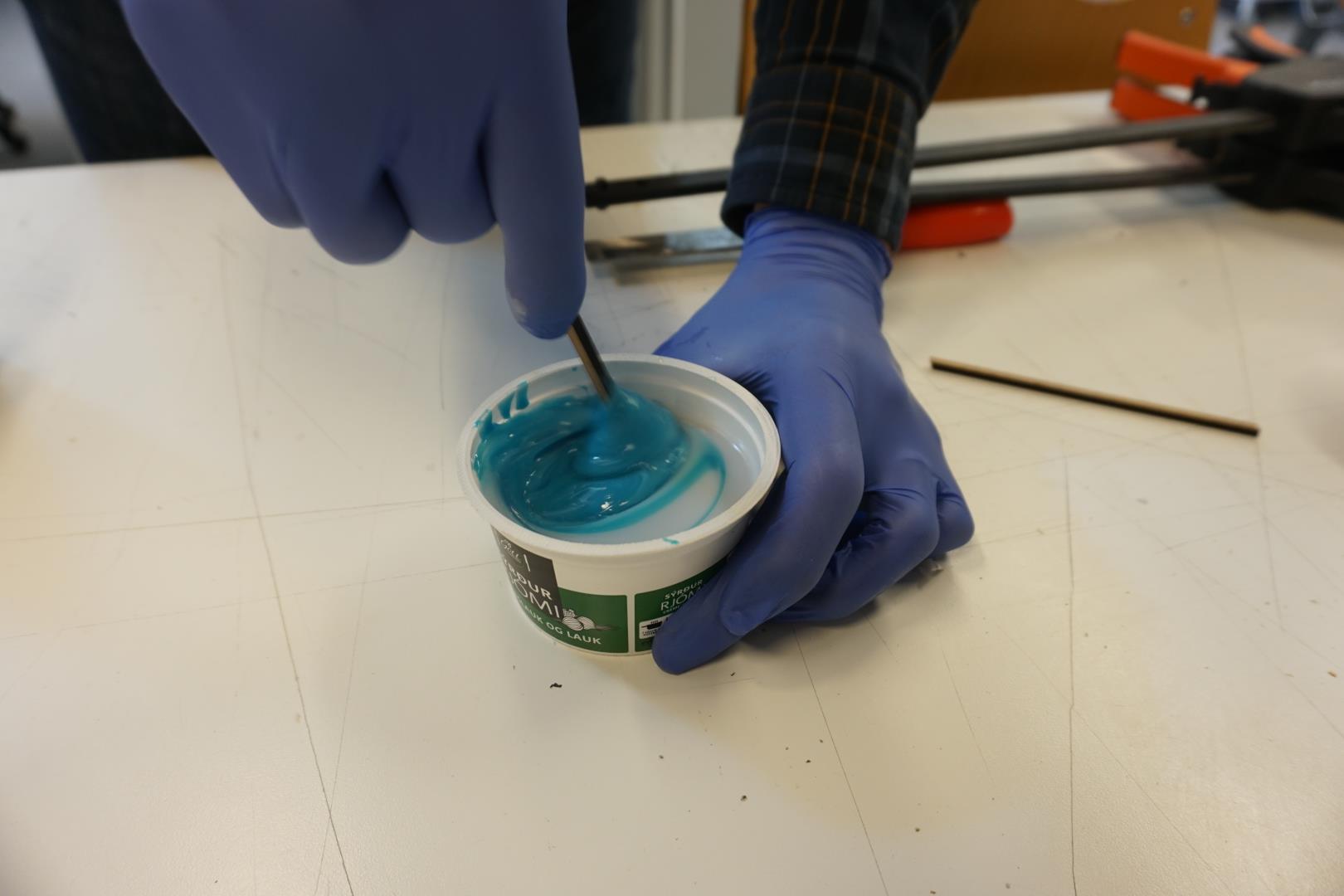
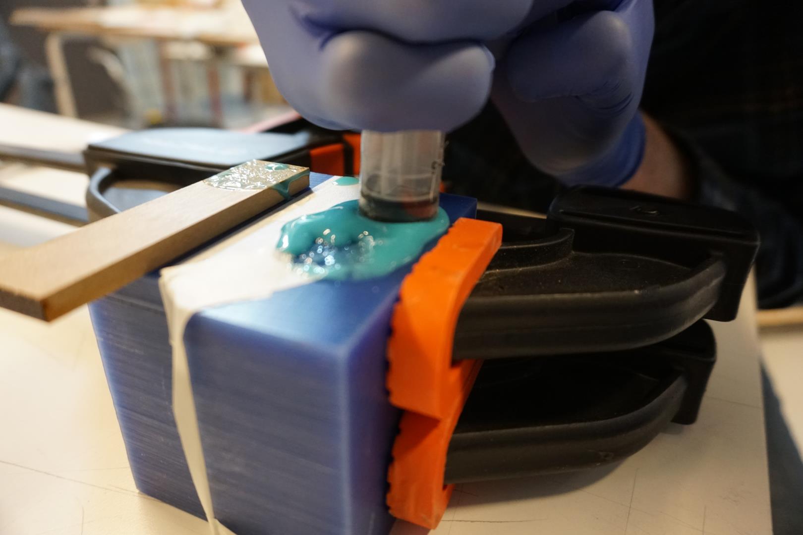
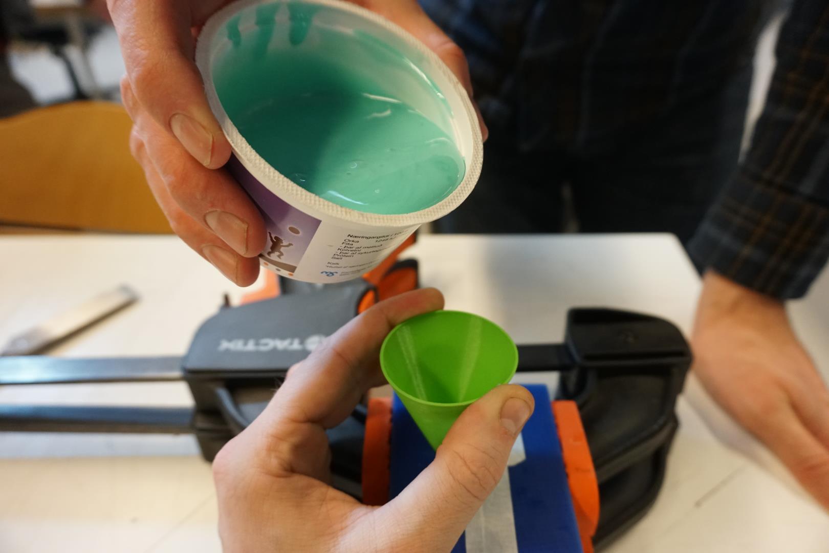
First I measured out even amounts, before combining them and mixing thoroughly.
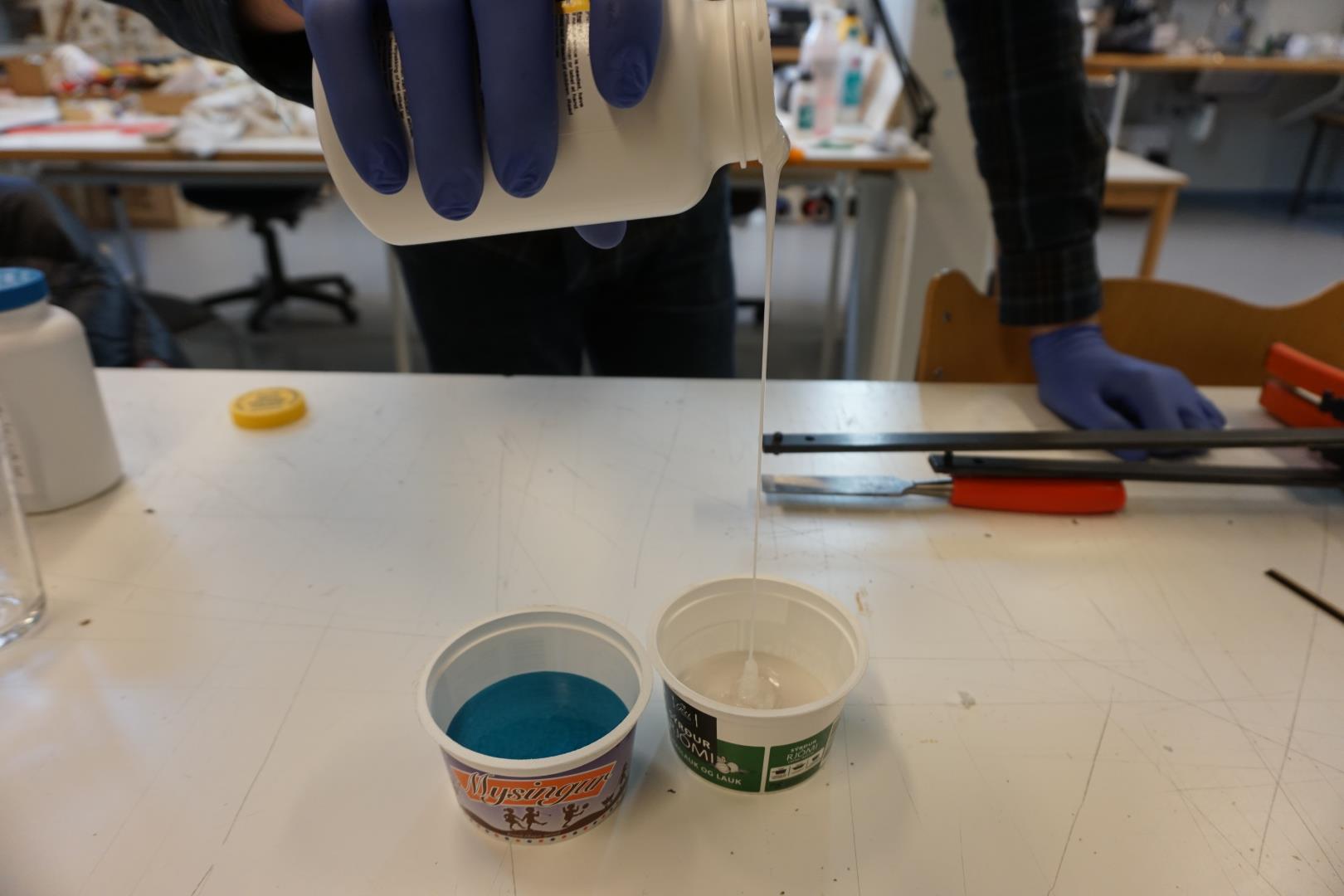
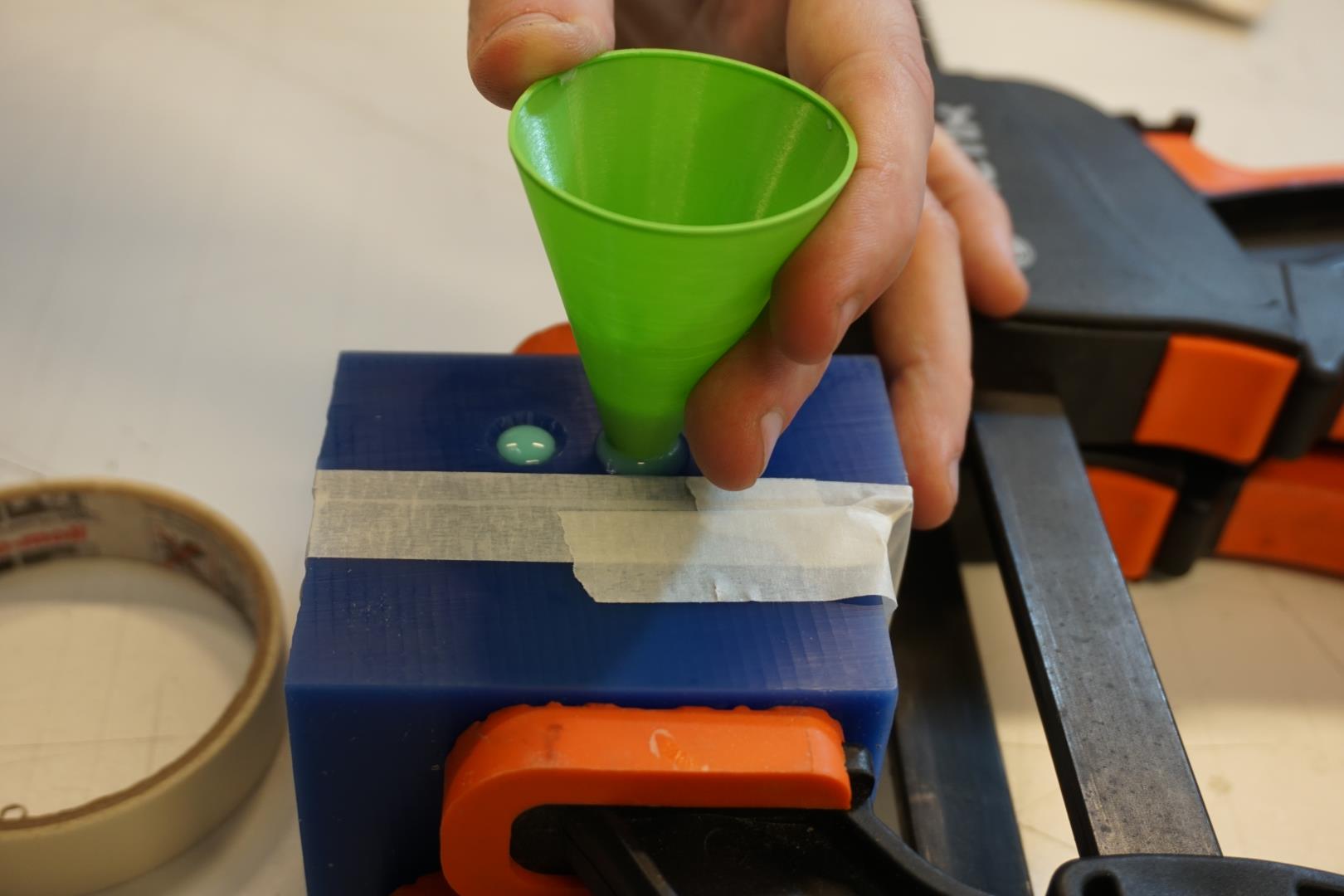
Once mixed well, I started pouring into the funnel.
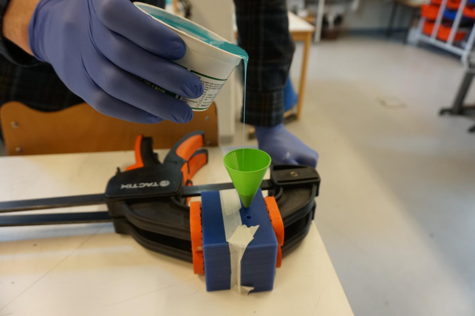
A slow steady flow of silicone is best, according to my sources. That limits the amount of bubbles in the mix.
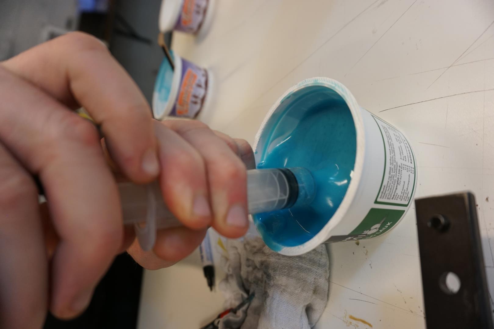
But here is where the trouble started. The viscosity of the silicone was already quite high and the funnel started jamming up. I tried to direct the stream directly into the holes without the funnel but that did not work well.
Last minute attempt at a solution was to use a syringe we had laying around in the lab.
At this point, I decided enough was enough. The rest of the silicone mix was pretty much set and there was nothing more to do. A timer was set for about 30 minutes before checking the result.
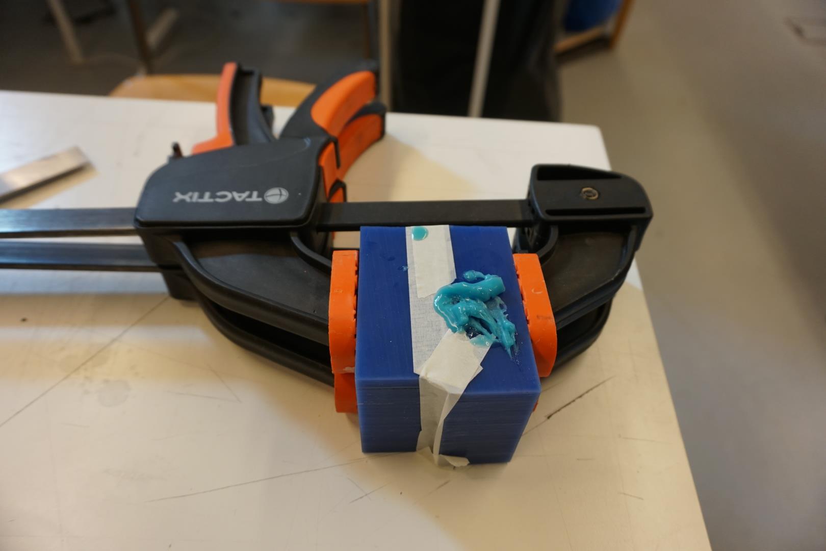
Cut to 30 minutes later...
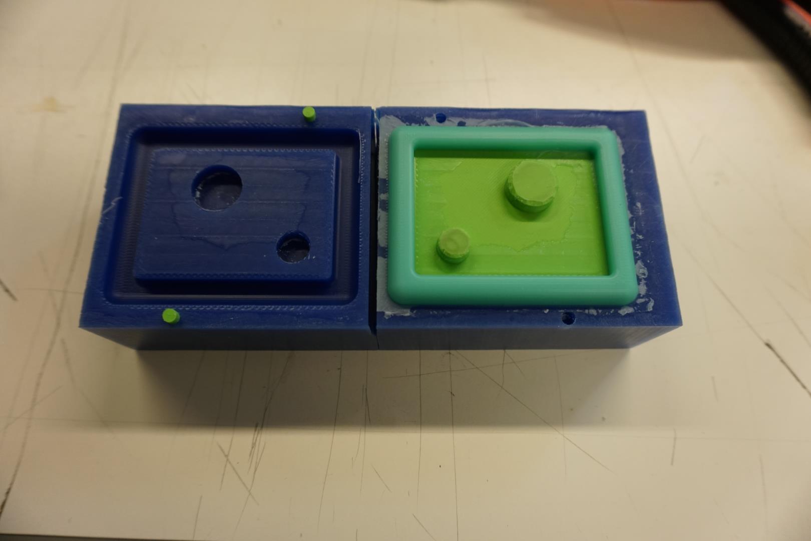
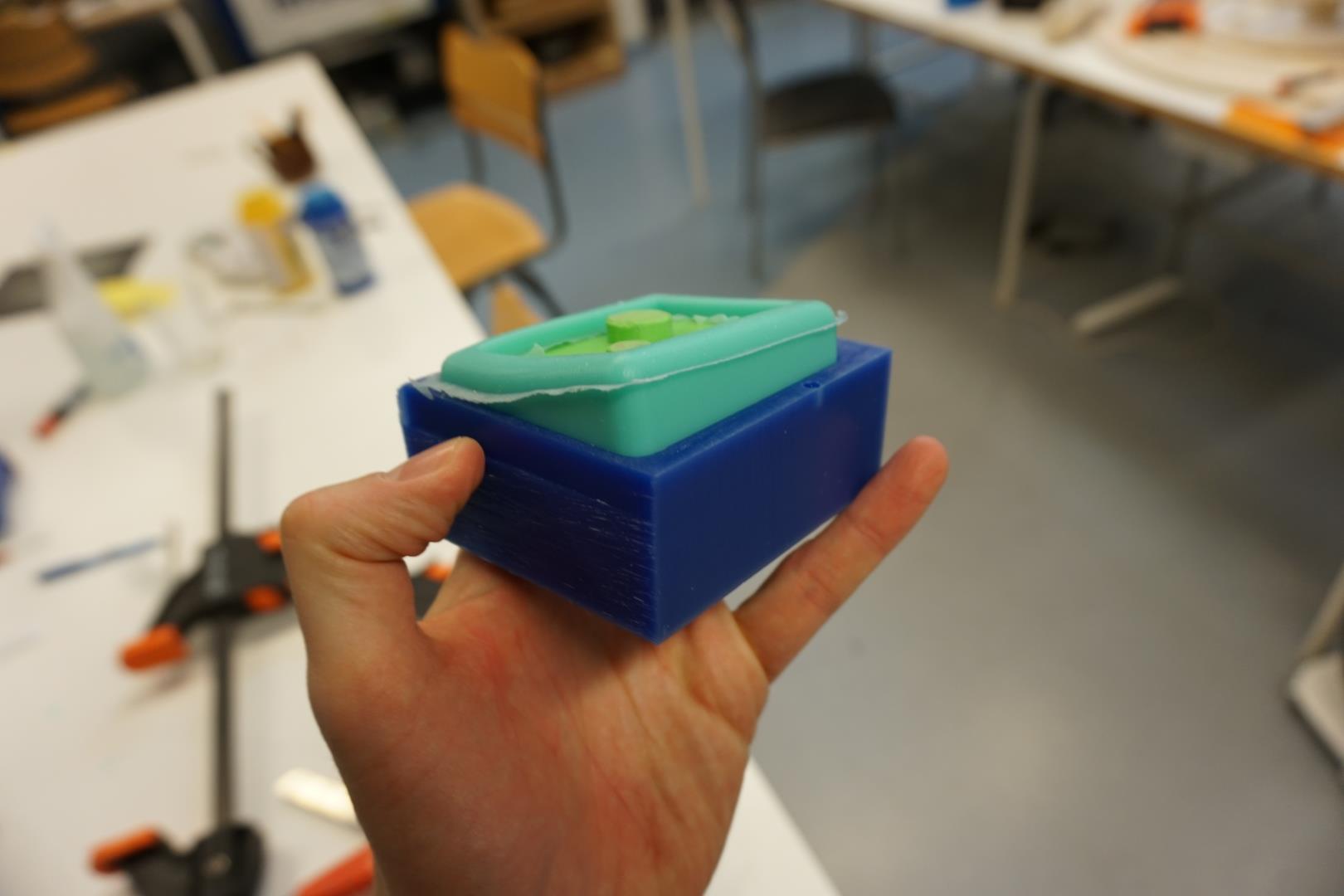
It is now time to remove the mold and check what horrors awaits us!
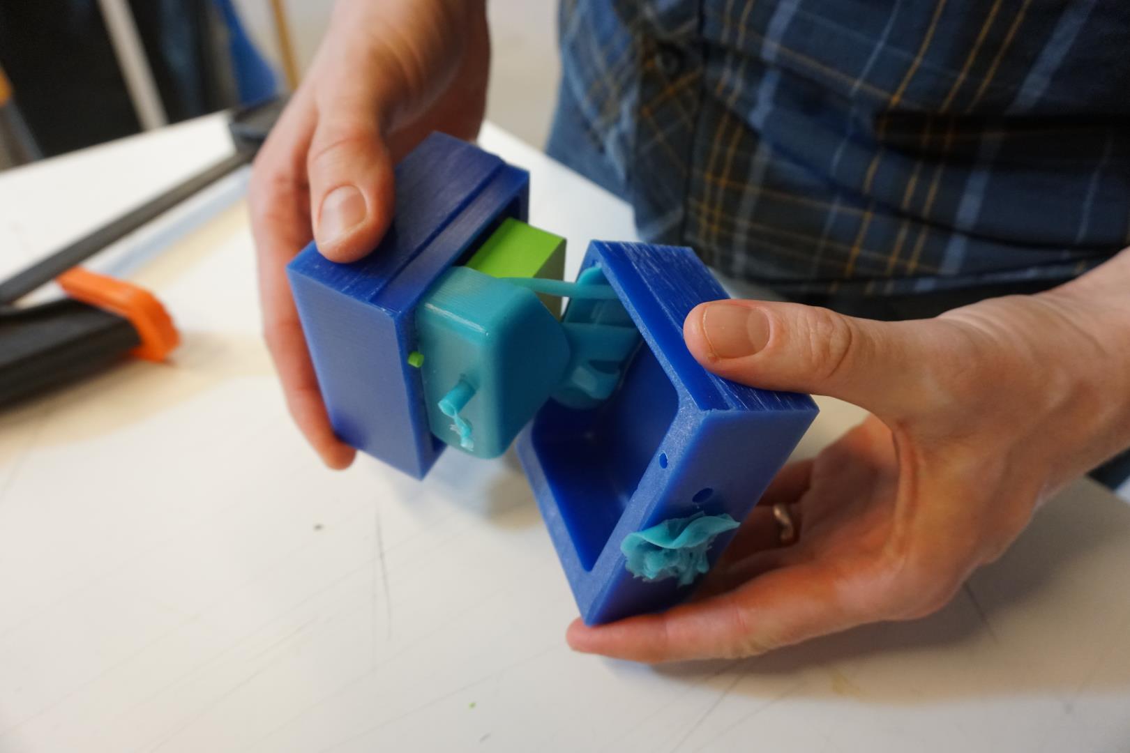
One side is now off, we can start to inspect the silicone…
Removing the rest…
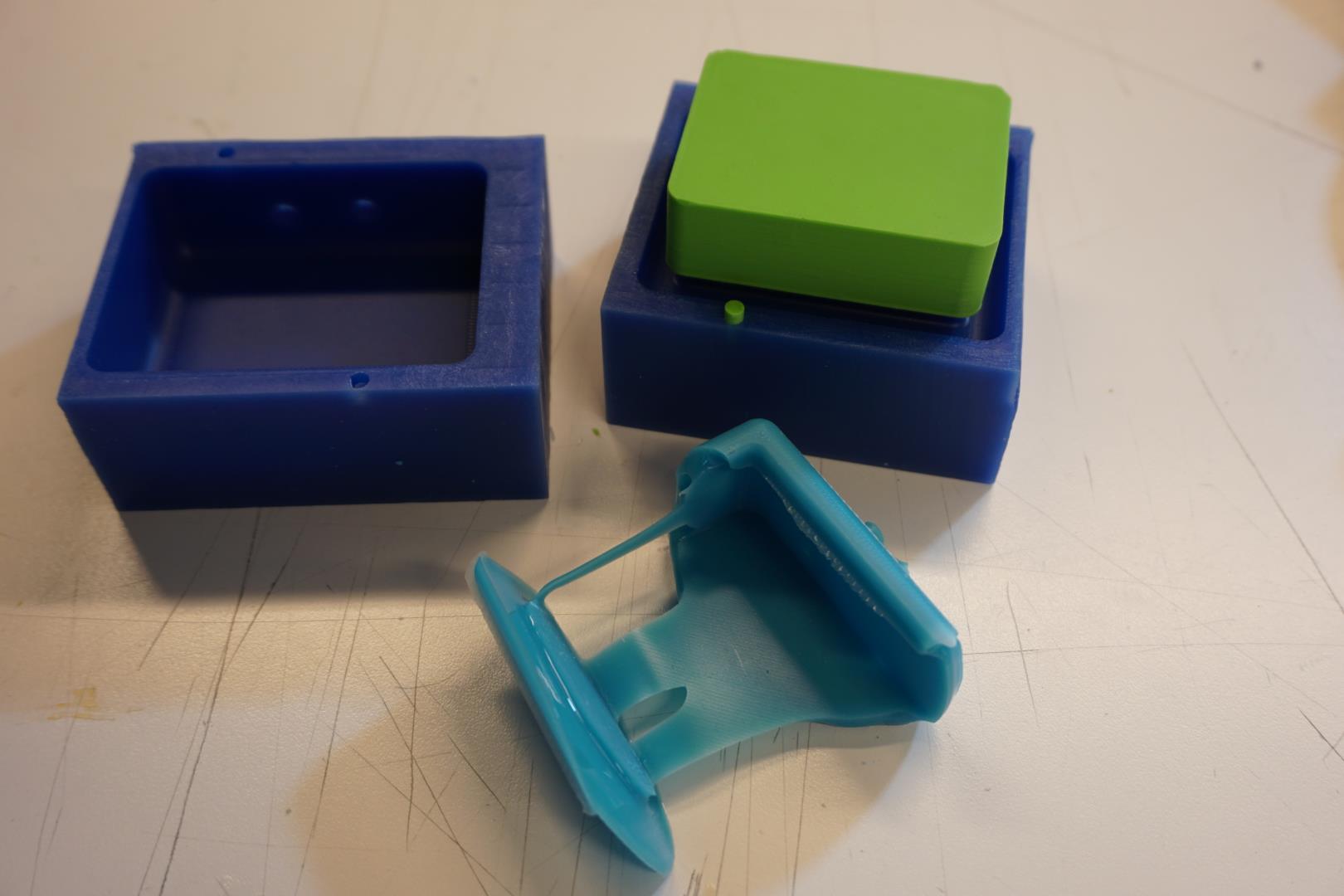
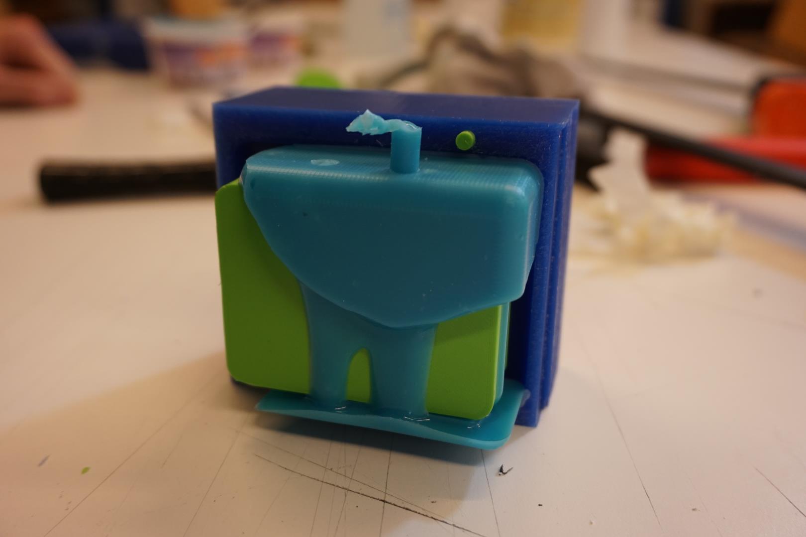
Alright… this is of course a failure. But there are positives here!
The parts that actually filled well with silicone, are very nice! No bubbles visible, extremely smooth, very little extra material that needs to be removed.
I was very surprised of how easily the silicone could be removed. I did not use any release agent and did not know what to expect.
Casting #2
Having learned that the quick curing stuff actually cures quickly, I mixed up another batch but now with the SLOW curing stuff.
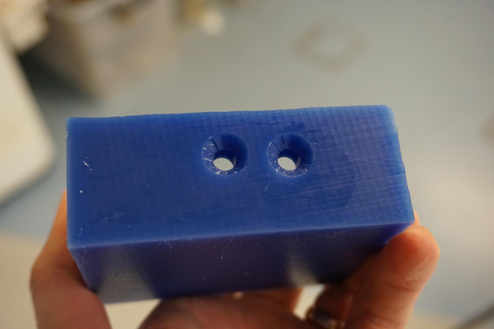
I drilled out the two holes I made, to 8mm, and countersunk them. I did this, hoping to improve the flow of the silicone. I also cut a bit of the bottom of the funnel, thus increasing it’s width.
Yet again, borrowing a set of extra hands, I started pouring the silicone into the mold. The color of the mix is a slightly paler blue, there may have been a bit of a mis-calculation on my part or they are simply a bit different, I’m not sure.
But this time, the flow was much better. I managed to maintain a steady flow of silicone through the funnel until it started rising through the vent hole.
Using a small hammer to tap the mold throughout the process is a good tip to help the silicone settle and for air bubbles to rise.
The curing time of the SLOW version is about 4 hours, so after making sure the mold is actually full, I returned to other duties (documentation and home, in that order!).
We must now wait until tomorrow to see the result!
Success!
This morning I peeked into the Fab Lab to see how the casting went. Nothing seemed to have leaked outside of the mold, no big mess! That’s good!
It was way more difficult to take apart then with the earlier attempt. That must be because the cast had filled in well, creating friction/hold.
Getting the mold all the way out took some time but I managed to do it without any damage.
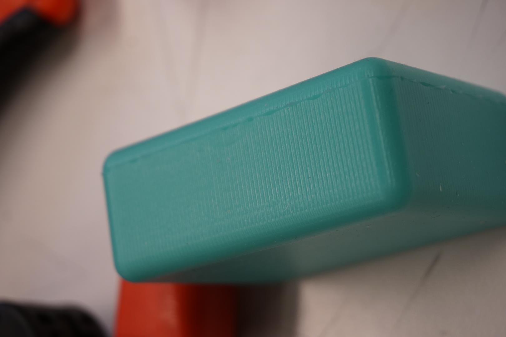
But it’s looking real good! Not so much material to clean up it seems.
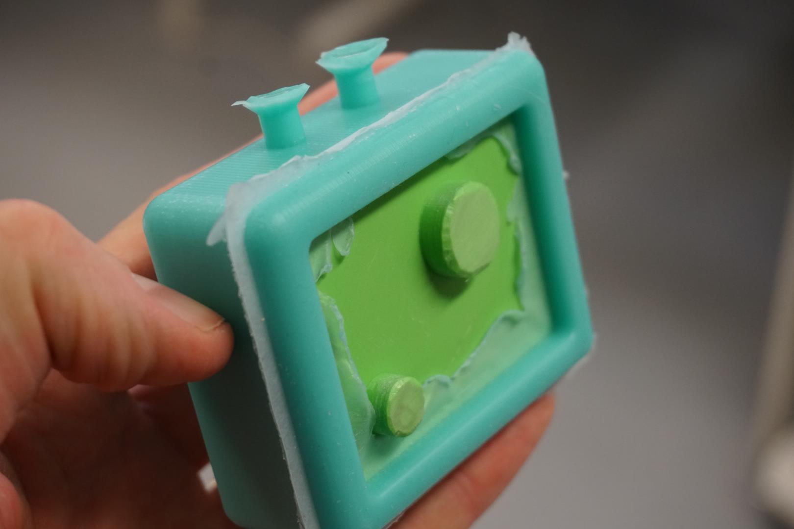
It turned out I kind of made a GoPro bumper case without planning to!
It was also fun to see that the molds held up well, I’m kind of surprised of how strong this high speed wax is. I’ve never used the stuff before, but I’m really happy with it!
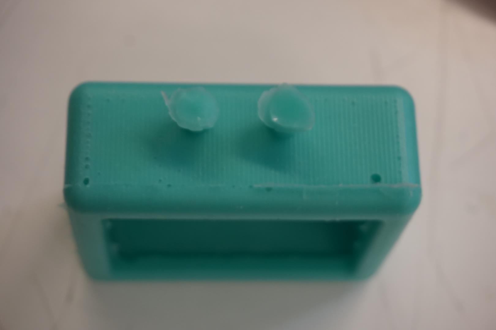
The two holes, for input and venting, filled up and had to be cut off. That was no big deal to do.
On the top side there are bubbles visible. They are not very big but are noticeable in close range. So it’s not a perfect cast! (but close, yes?)
When inspecting the silicone, you can see the tiny grooves left by the tools. They are in no way deep but still, they are noticeable.
Conclusion
Molding and casting is fun!
In this week I used various tools, both physical and digital to create a perfectly functional cast! The end result is even better than I had hoped for, though it’s not production quality. But that’s OK!
I learned quite a bit during this process, I’m more comfortable with the Roland machine and the Manufacturing processing within Fusion360.
Toodaloo!
Update
Collecting the wax shavings for repurposing:
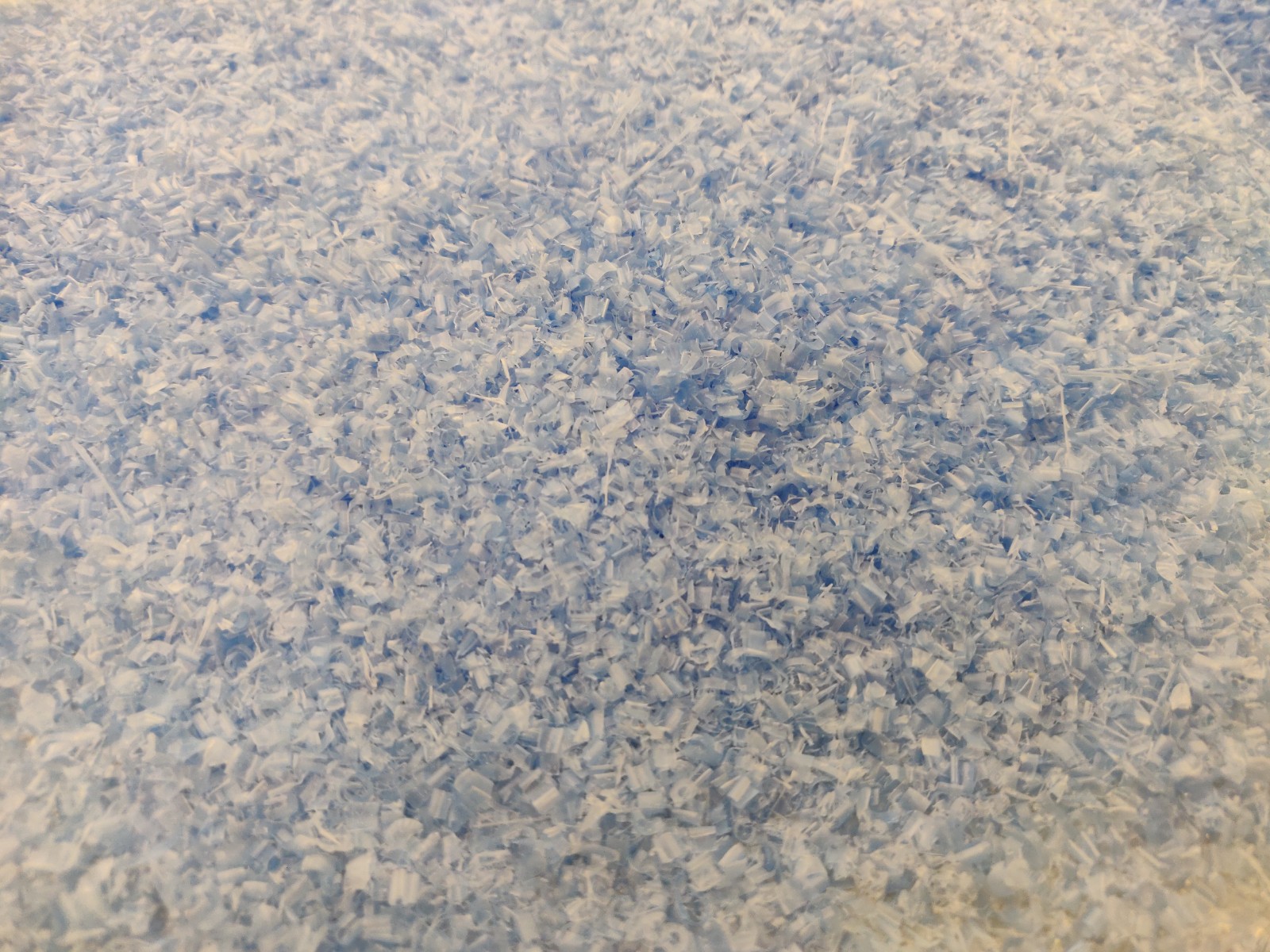
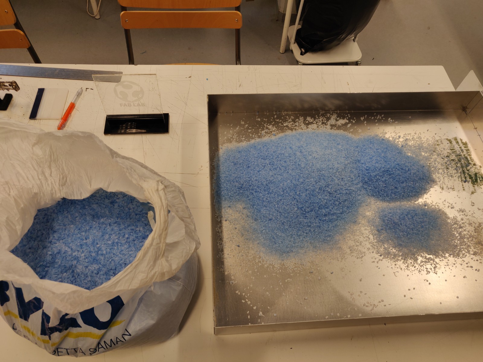
This makes the earth happy!