4. Computer controlled cutting
Weekly assignments
This weeks assignments are to:
- Cut something on the vinyl cutter
- Characterize the laser cutter
- Design, lasercut and document a parametric construction kit
- Design
- Cut
- Document
Vernier scale
I started with characterizing the laser cutter. First thing I was to measure the MDF material I’ll be working with.
Using a caliper, I measured the thickness of the material. It’s sold as 4mm thick, so lets verify that.
I broke off a piece of the material and measured the thickness. Before looking at the actual measurement, let’s refresh our caliper knowledge.
On the caliper, there are multiple scales.
The most prominent one is the whole millimeter (mm) scale. It’s the one on the main shaft, so if a measurement lands exactly on a line there, using the 0 point on the movable jaw as a guide, it’s a tight mm fit.
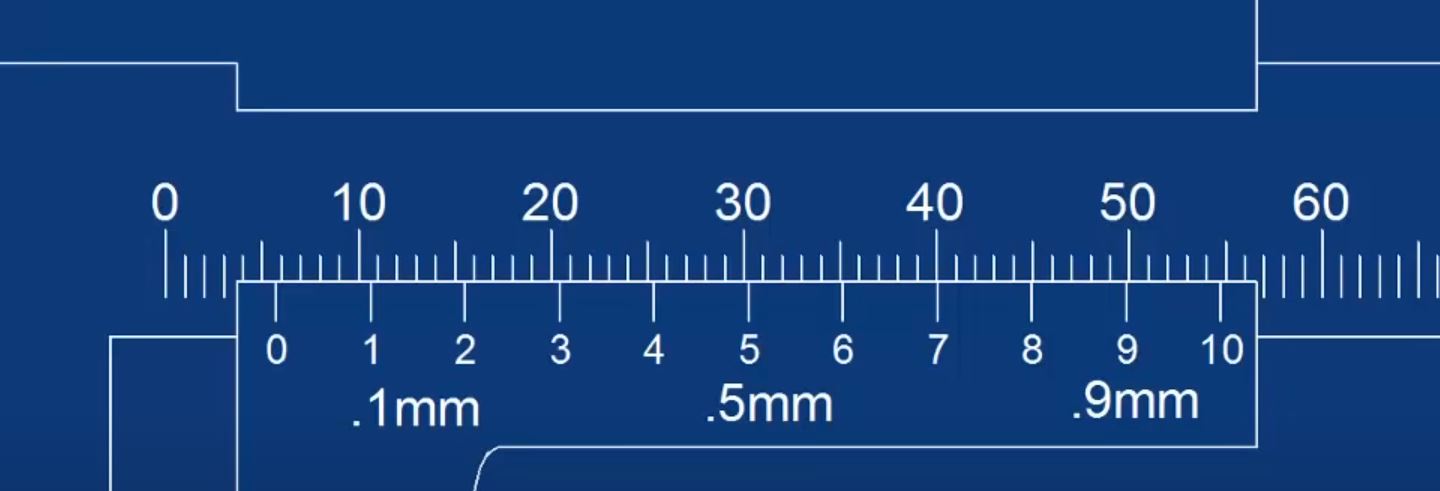
If it does not land there, you must look at the larger markings on the movable jaw. Looking at the picture above, it reads as 5.7 mm.
(Pictures above screengrabbed from WeldNotes)
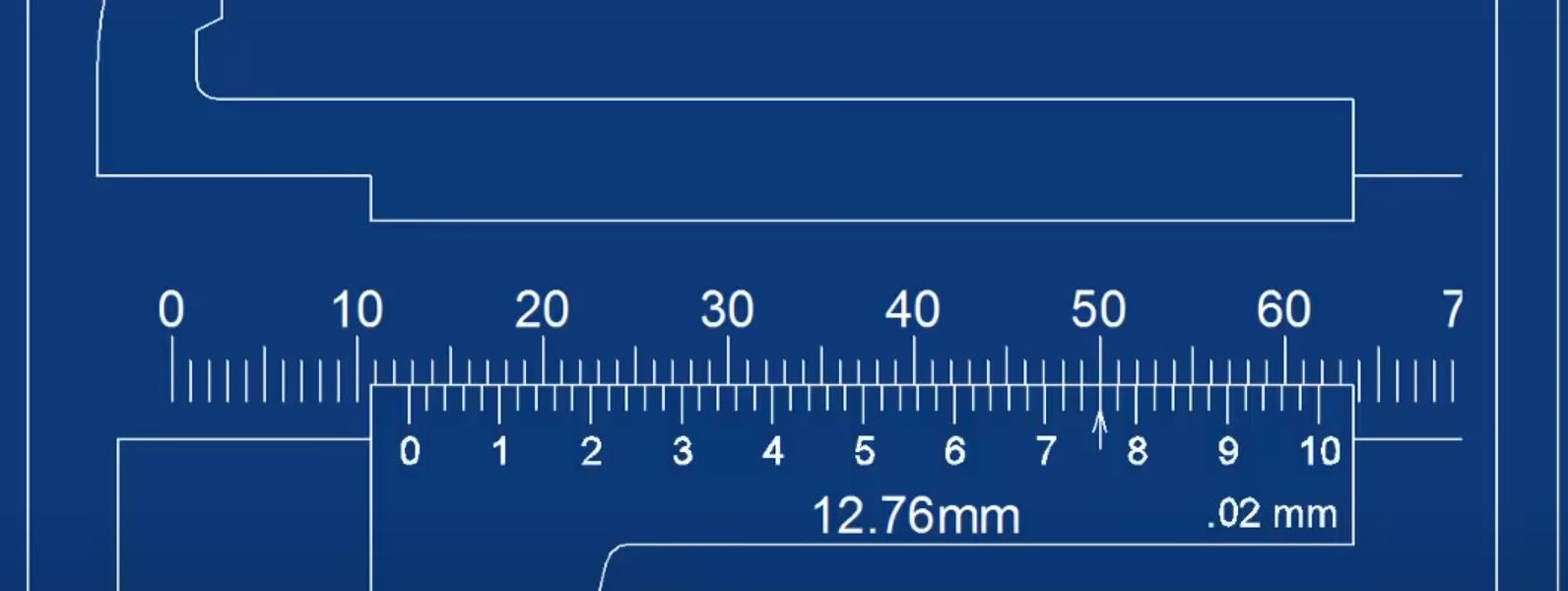
Going even further, if none of the larger lines on the movable jaw line up perfectly, you must look at the smaller scale markings. Each of them represent 0.02 mm. On the picture above, it reads as 12.76 mm.
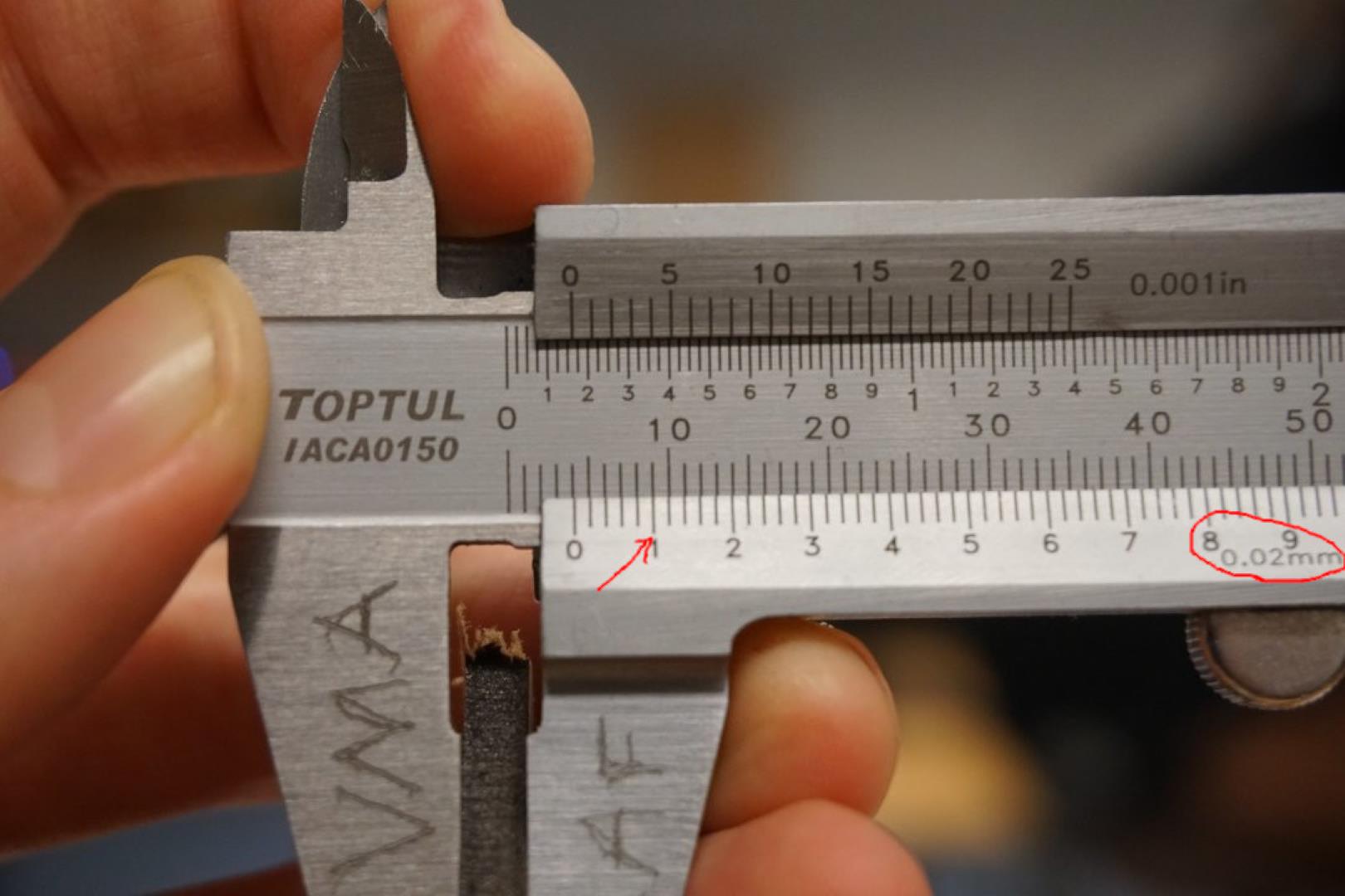
So the piece I measured is 4.1 mm thick. Thats good to know!
Cutting
Safety first!
Safety is important and when using the laser cutter, just like most other tools, you must practice safety!
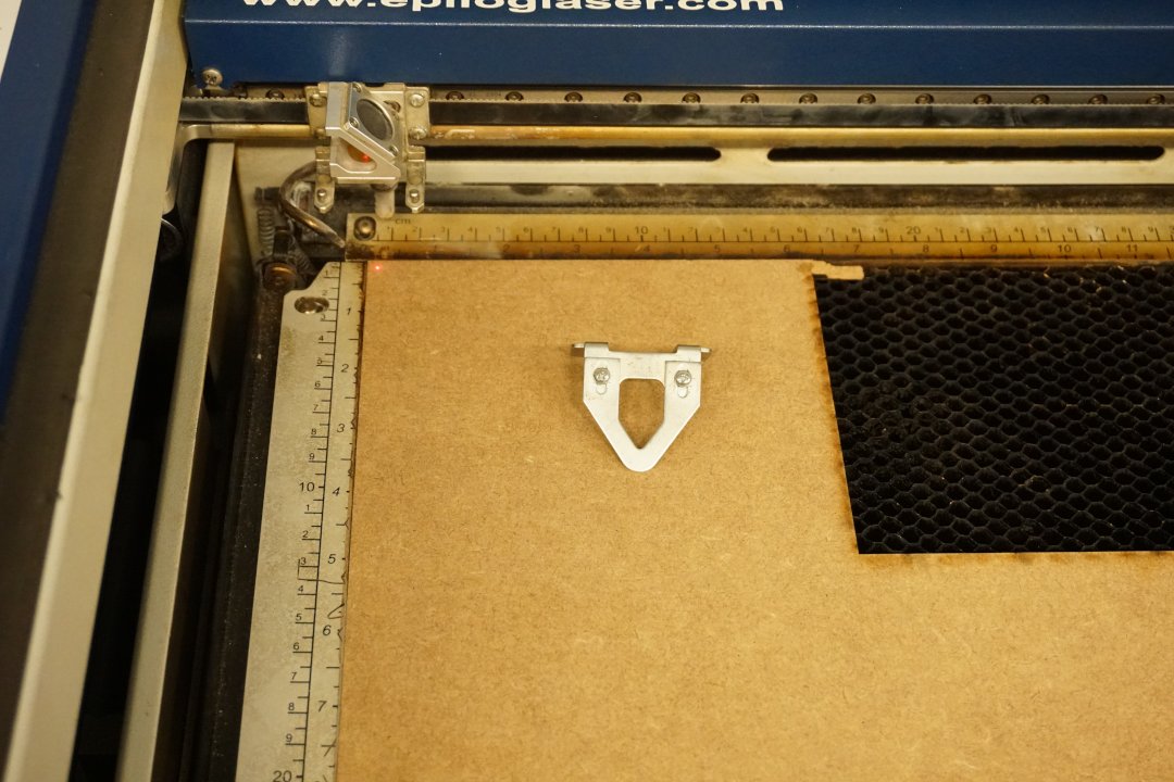
In our lab, we have two Epilog laser cutting machines. Attached to them are two important items, a air compressor and ventilation.
You must always use the ventilation, as the machine emits smells and possibly hazardous gases when working! This is different between materials, so please read any and all safety instruction related to the material you are working with!
The compressed air is used when cutting, it is blown at the cutting point to held clear debris and put out / blow away any flames and smoke. This helps protecting the equipment, such as the laser lenses and provides a cleaner cut.
The Epilog machines have a safety switch on the lid, which is made out of protective glass, and it shuts the laser off if opened. This way, any harmful rays should not escape. Watching the laser work is mesmerizing but I’d like to recommend you do not!
You only have a single set of eyes, please take of them. Same goes with your lungs, please let the smoke/fumes clear!
Finally: DO NOT LEAVE THE LASER CUTTING MACHINE INATTENTIVE! IT IS A POTENTIAL FIRE HAZARD!
Let’s cut!
I loaded the MDF into one of our laser cutter, which is an upgraded (40w -> 60w) Epilog machine. I started using with Epilog settings for 3mm wood.
First attempt - 3 mm wood settings
| Speed | Power | Frequency |
|---|---|---|
| 30 | 40 | 500 |
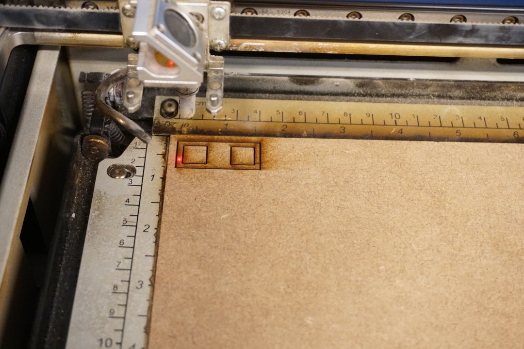
No supprise, it did not cut through the material.
Second attempt, more power!
| Speed | Power | Frequency |
|---|---|---|
| 30 | 100 | 500 |
Higher power, noticed more burn around the edges.
Third attempt
| Speed | Power | Frequency |
|---|---|---|
| 20 | 100 | 500 |
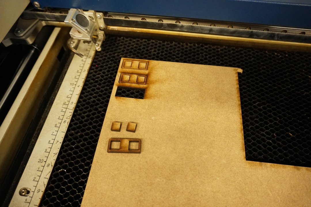
This time, it cut through the material.
Pictured are the three attempts, respectively.
Measuring the kerf
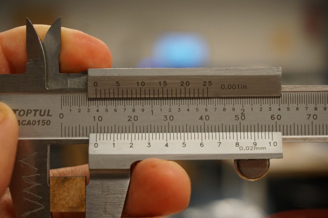
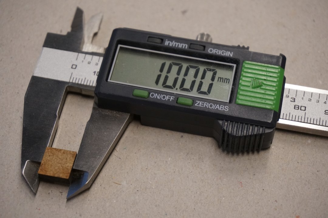
Measuring the supposedly 10 mm x 10 mm piece, using the Vernier scale on the caliper, I found that it was actually 9.82 mm thick. Me, getting old and over over 10 years since I had my laser eye surgery, wanted to double check the measurements and found a digital caliper.
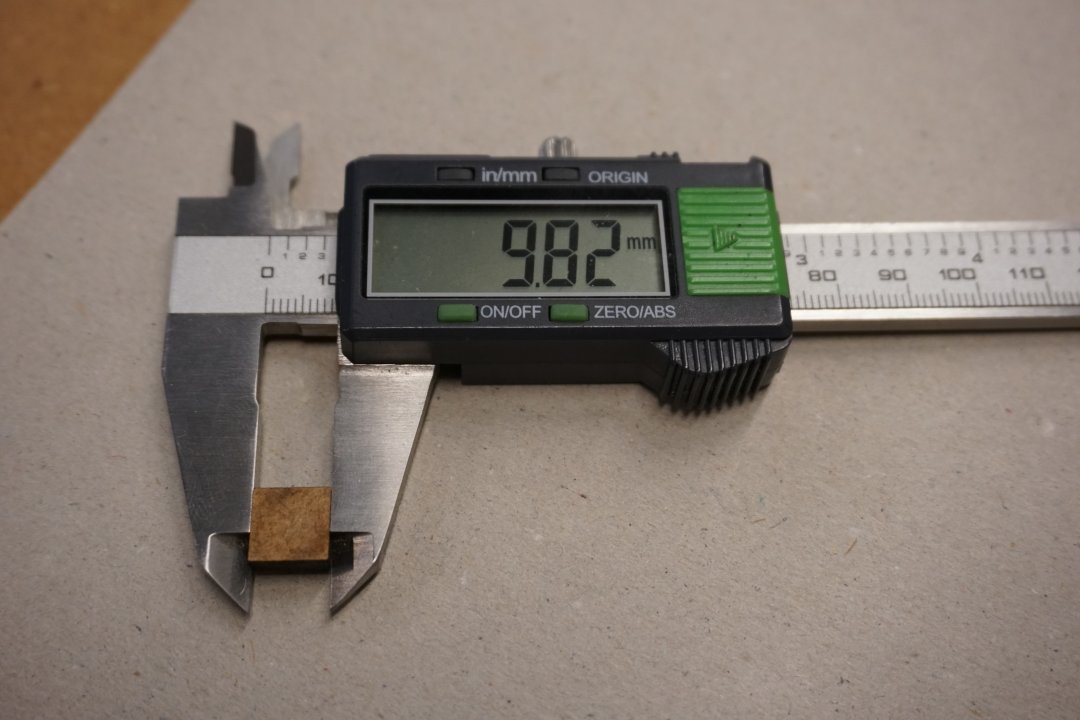
Voila, I got the right measurement!
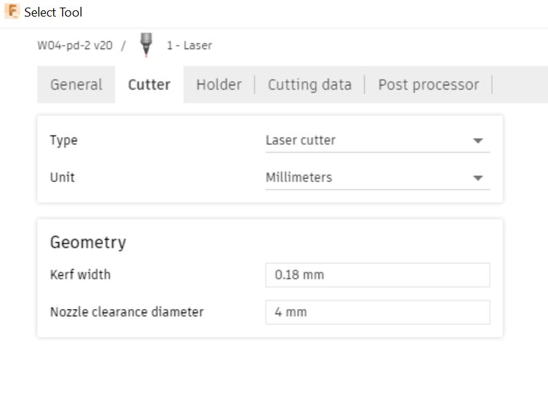
Calculating the kerf is simply:
10 - 9.82 = 0.18 mm
So to account for the kerf on each side we use half of the kerf or 0.09 mm.
ASCII representation of the the laser and the kerf
                    Laser width
[---------------------0.18mm--------------------]

                 *******|********
             ***********|************
          ************* | **************
       ***********      |       ***********
     ********           |           ********
   ********             |             ********
  *******               |               *******
 *******                |                *******
******                  |                  ******
******                  |                  ******
******                  |                  ******
 ******                 |                 ******
 *******                |                *******
  *******               |               *******
   ********             |             ********
     ********           |            ********
       ***********      |       ***********
          ************* | **************
             ***********|************
                 *******|********

[--------0.09mm--------] [--------0.09mm--------]
I then created another set of squares, this time with a 0.18 mm kerf added to them and cut them.
Beautiful!
Laser-cut joint
Next I created a simple joint drawing, with respects to the kerf.
I then wanted to test the cutting with different speed settings.
Remember, I measured the kerf using speed of 20.
I cut the pieces with speed of 20, 16, 10 and 5. Pictured below are the results, respectively.
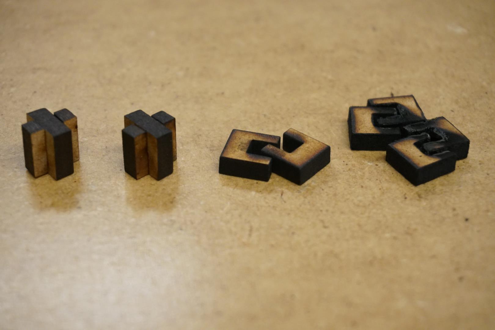
The one on the left(speed: 20) is snug as a bug, next one (speed: 16) is a bit loose, the third one (speed: 10) falls apart if you lift it, and the last one (speed: 5) is severely damaged.
So the kerf is highly dependant on the settings. So if doing very precise work, it’s necessary to examine the kerf and to adjust the project settings accordingly.
Other material
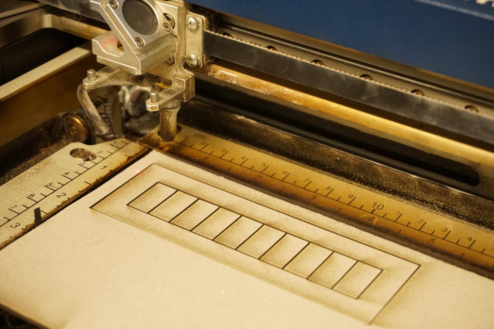
I wanted to see how kerf would manifest on other materials. I found hard paper, 1.2 mm thick, created a cutting image in Inkscape and went cutting.
I experimented with different settings, trying to find a setting that cut properly through the paper. Many of the settings left a bit so the paper stuck together, that was possibly the result of the laser moving to fast.
What I landed on was:
| Speed | Power | Frequency |
|---|---|---|
| 10 | 50 | 5000 |
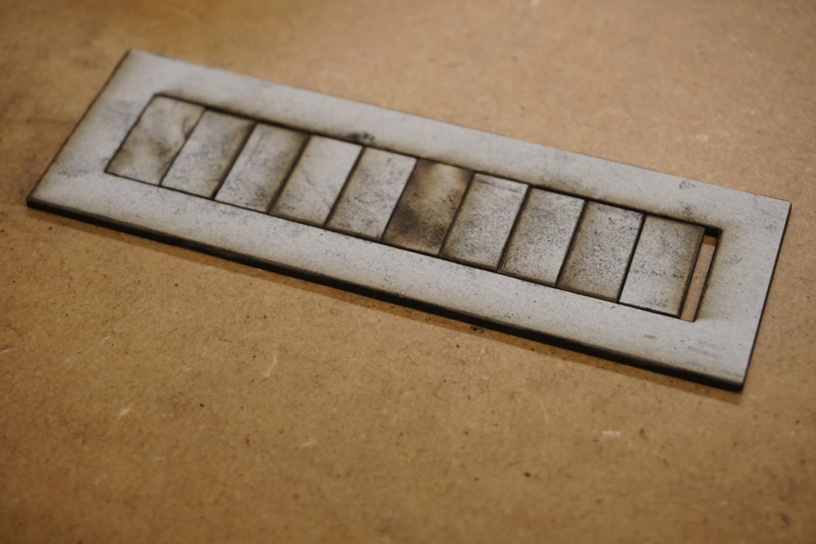
Then I created a vector of 10 slices with a box around it. I cut out the vector, slid all the slices to one side and measured the gap. It measured as 2.82 mm. Finding the kerf is then simply a matter of diving 2.82 mm by 10: Kerf = 0.282 mm.
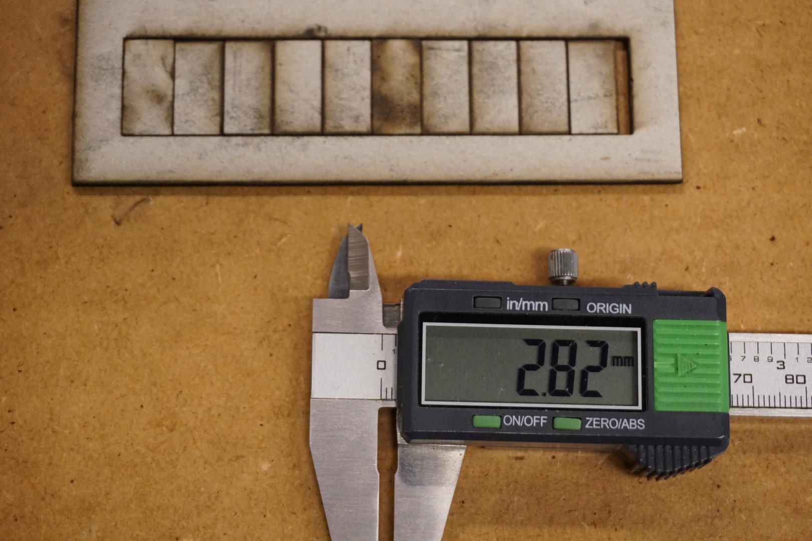
This method was mentioned to me by my instructor, Mr. Þórarinn Bjartur Breiðfjörð.
Vinyl cutter
| cut something on the vinylcutter
Thats pretty open so I thought I’d finally do something I’ve wanted to do for a while.
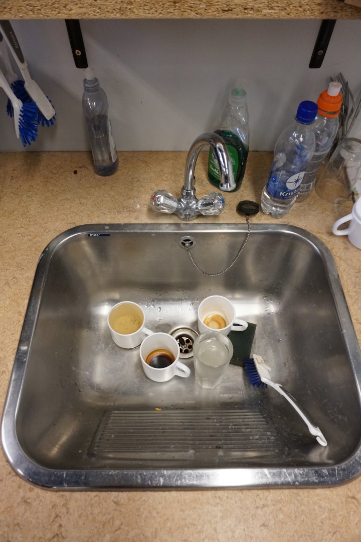
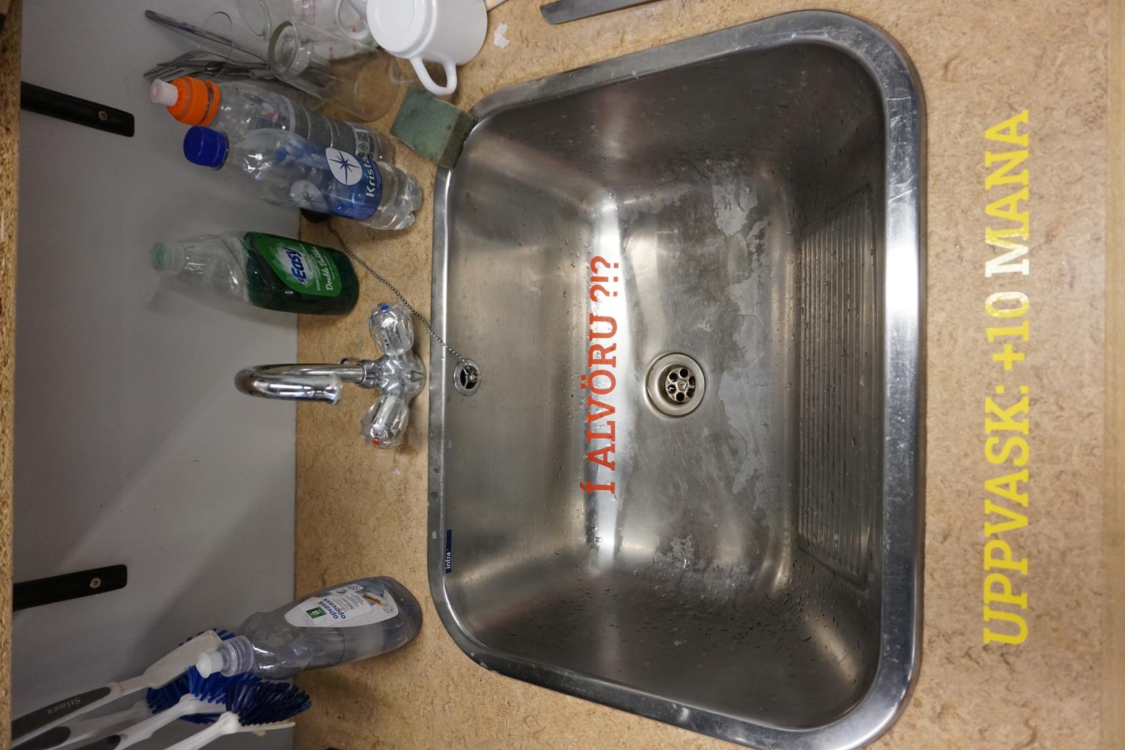
In our lab there is a coffe machine and a sink. The coffee is free for users of the lab and so is the sink. The cost of dishwashing liquid is included in the free price tag. But somehow the sink is not working. Atleast the washing up part of it. It holds the dirty cups well but I do not believe it is the correct usage.
If we project the status shown in the following picture, after one day, after 10 days there will be 30 dirty cups and 10 dirty glasses there.
This is suboptimal and must be improved. As stated in the lecture, the vinylcutter is underused but is able to solve a wide range of problems.
Let’s find out how useful it really is!
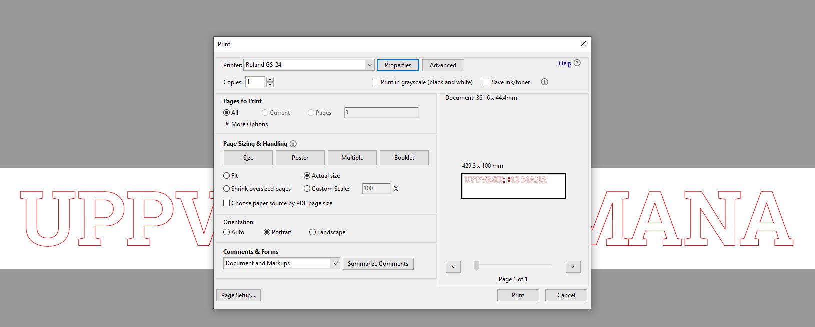
Designing the message(s)
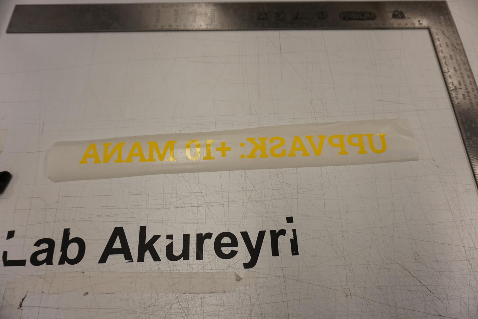
I used Inkscape to create a couple of messages.
I measured the size of the places I wanted to mark and then created a square with the same size.
I then added a text to the square. Once I was satisfied with the message, I used the same settings for
fill and stroke as I were to cut them with the laser.
I then used the Object to path setting to convert the text to usable paths.
Problem!
I saw that the convertion created a bit of mess, some of the letters would be cut way too much.


This was fixed by first running the ungroup function on the message. Then I selected the troublesome letter and used the union function to merge the parts.


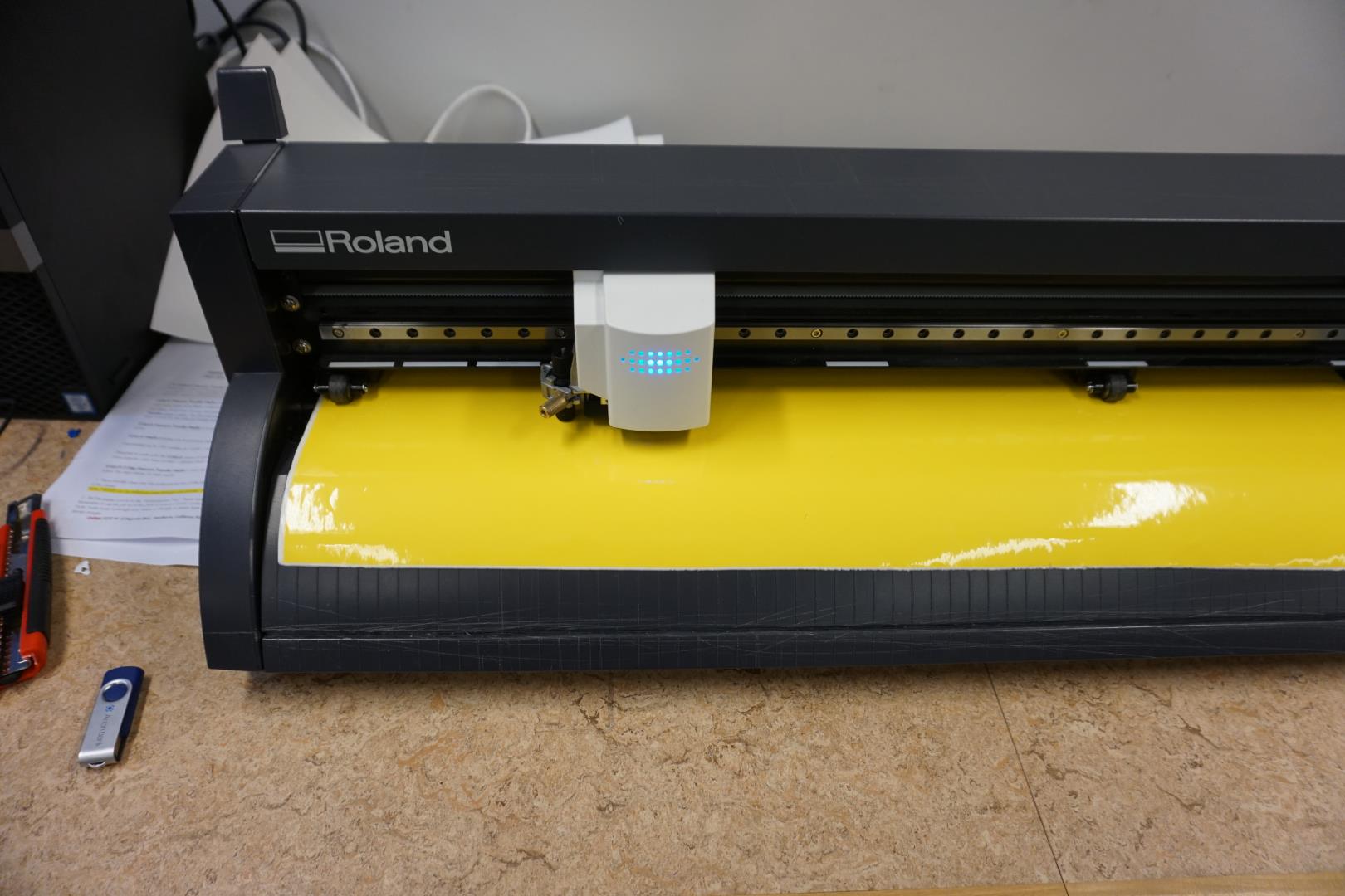
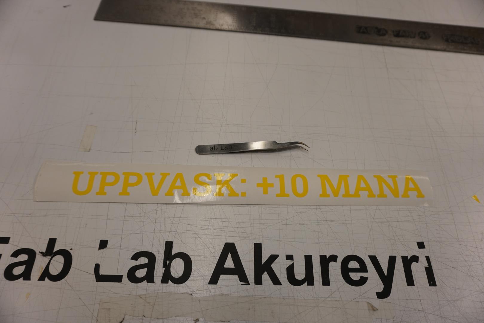
Testing the vinyl cutter
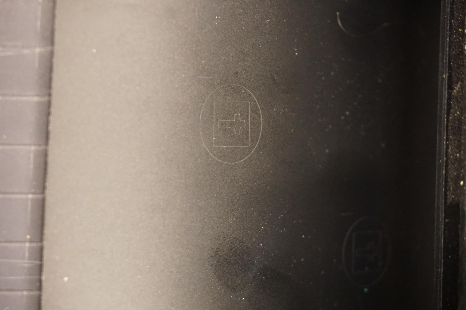
It’s a good idea to test the machine before you start using it. I loaded a small cutoff piece into it and hit the Test button. This cuts out a t, within a square, within a circle. You can then try to peel the sticker off the paper. You can adjust the force if needed.

It turned out the force was fine, 100gf, but I wanted to see how it would act if it was too high. I increased it to 300gf and ran another test.
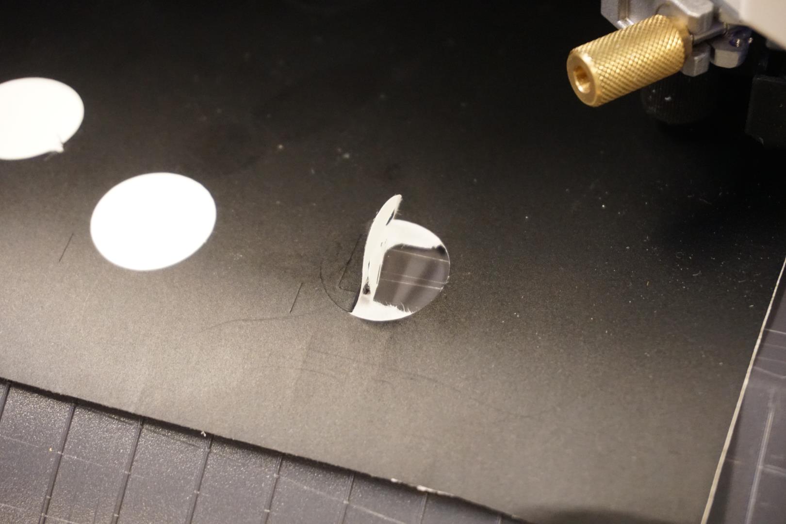
This time it cut way to deep into the material so it came apart when I tried to peel the sticker of the paper.
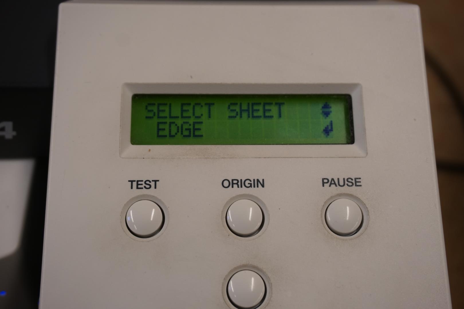
Cutting the message
I picked a bright yellow color for the first message. I loaded it into the machine and used the Edge setting to have the machine detect the edges and you set zero point and height.
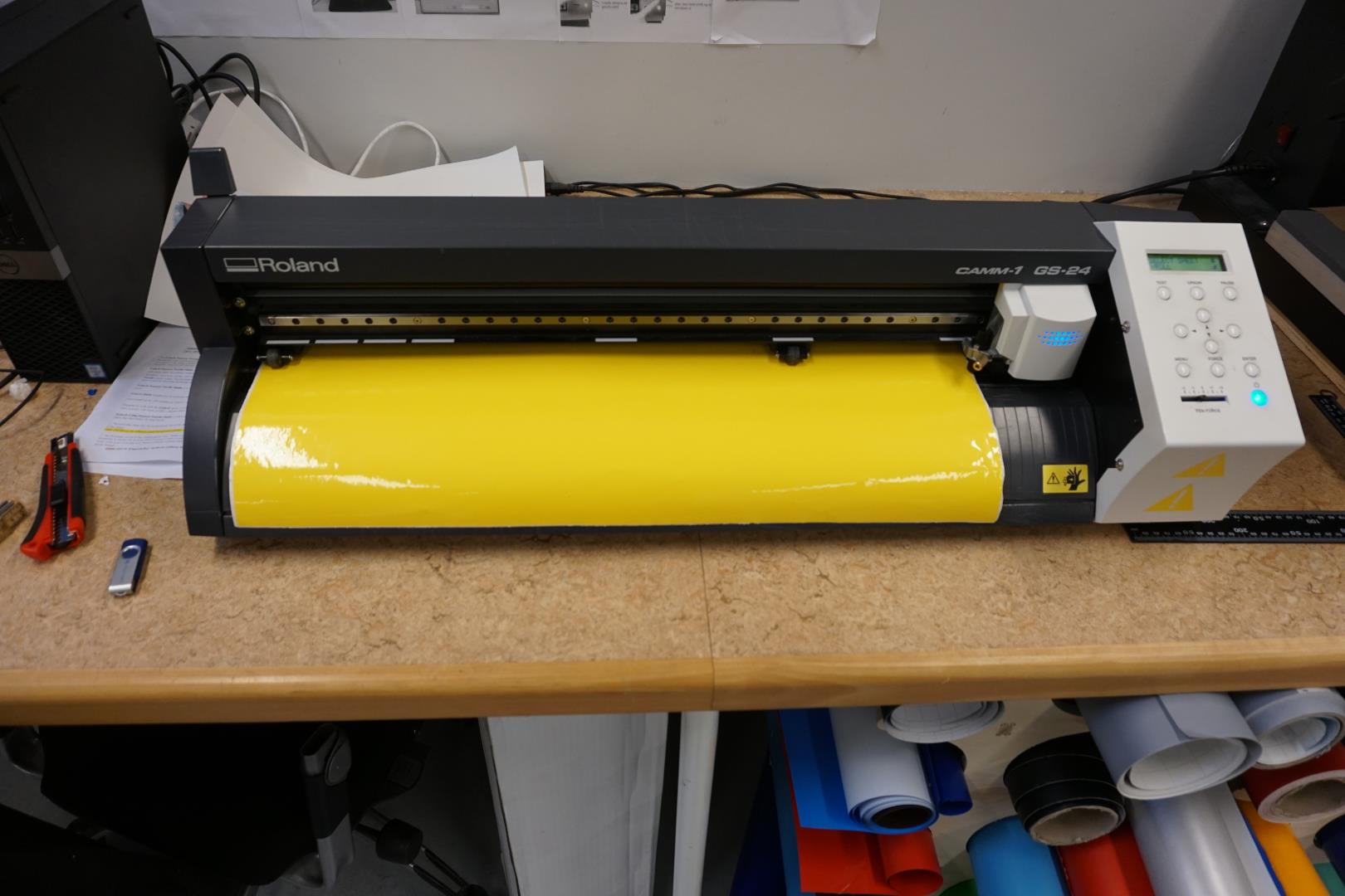
The other options is to select Roll or Piece.
Roll assumes you have a whole roll to work with, good for very large cuts. The machine finds the width, you set the zero point and it then assumes you have plenty of material to work with.
Piece makes the machine find the width, zero point and the height. Very good to make use of rest of material.s
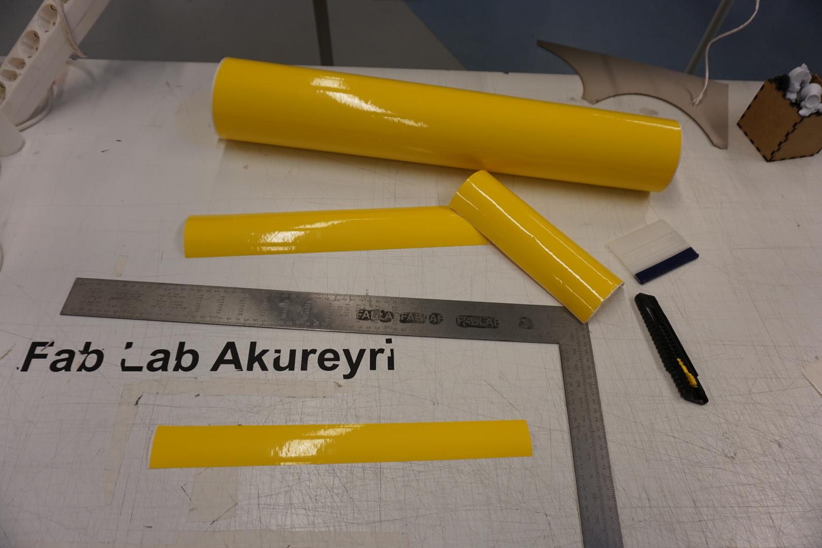
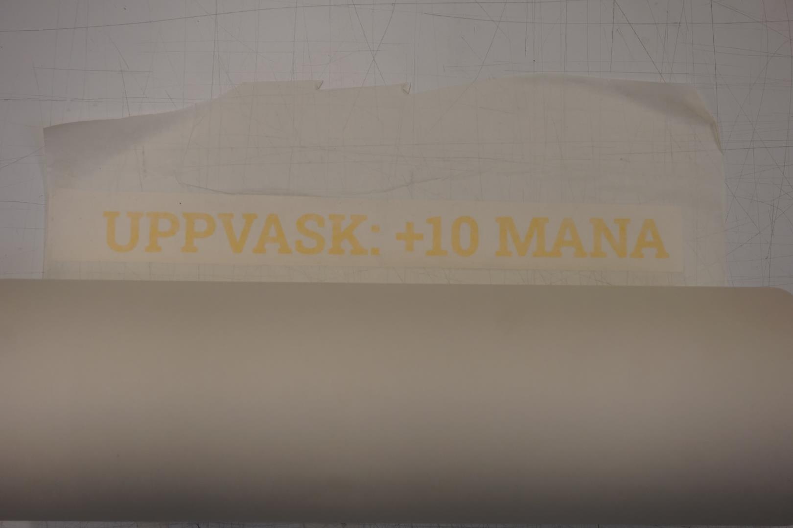
I made a bit of a mistake when setting up. I failed to set the height, so there was a bit of excess material. I cut them clean off and put in the pice bin for later use.
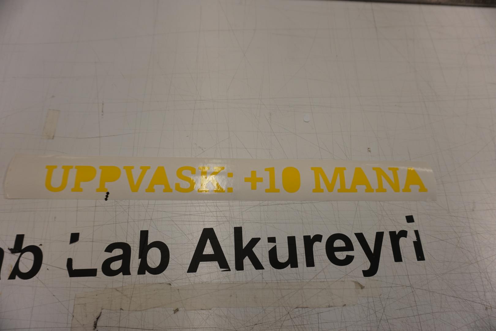
Once finished peeling, it’s time to put the sticker on transfer paper.
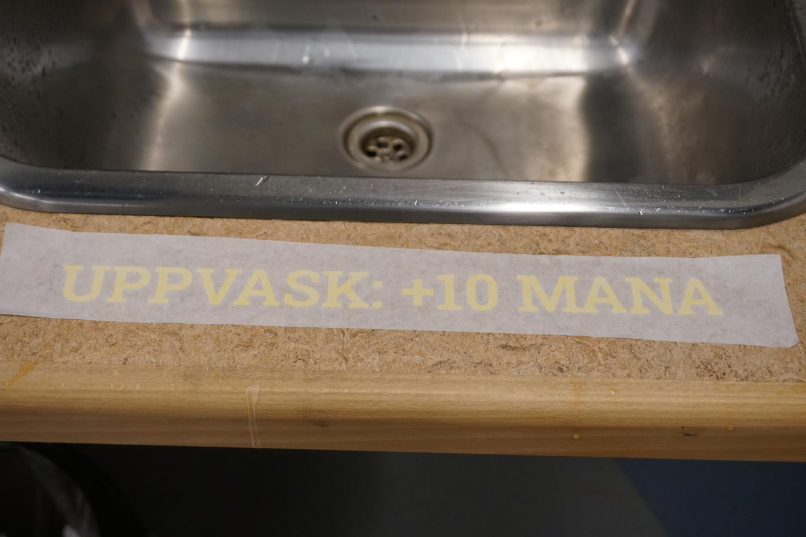
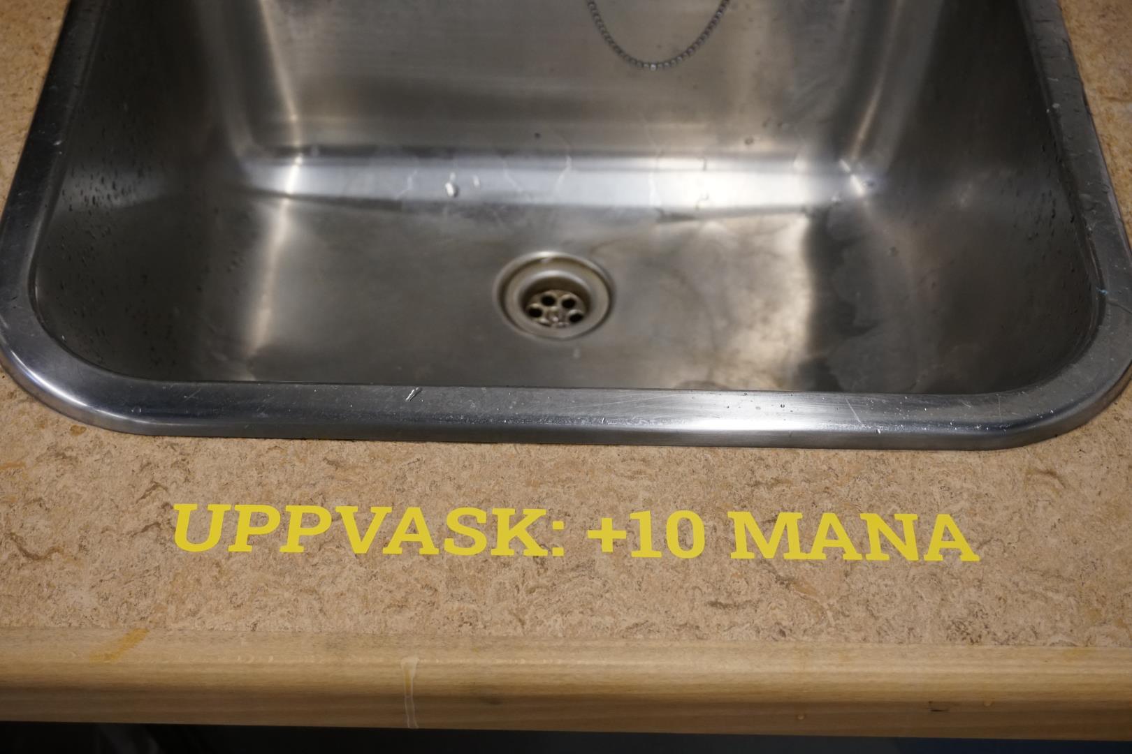
I then repeated the process for the sink, with a different message.

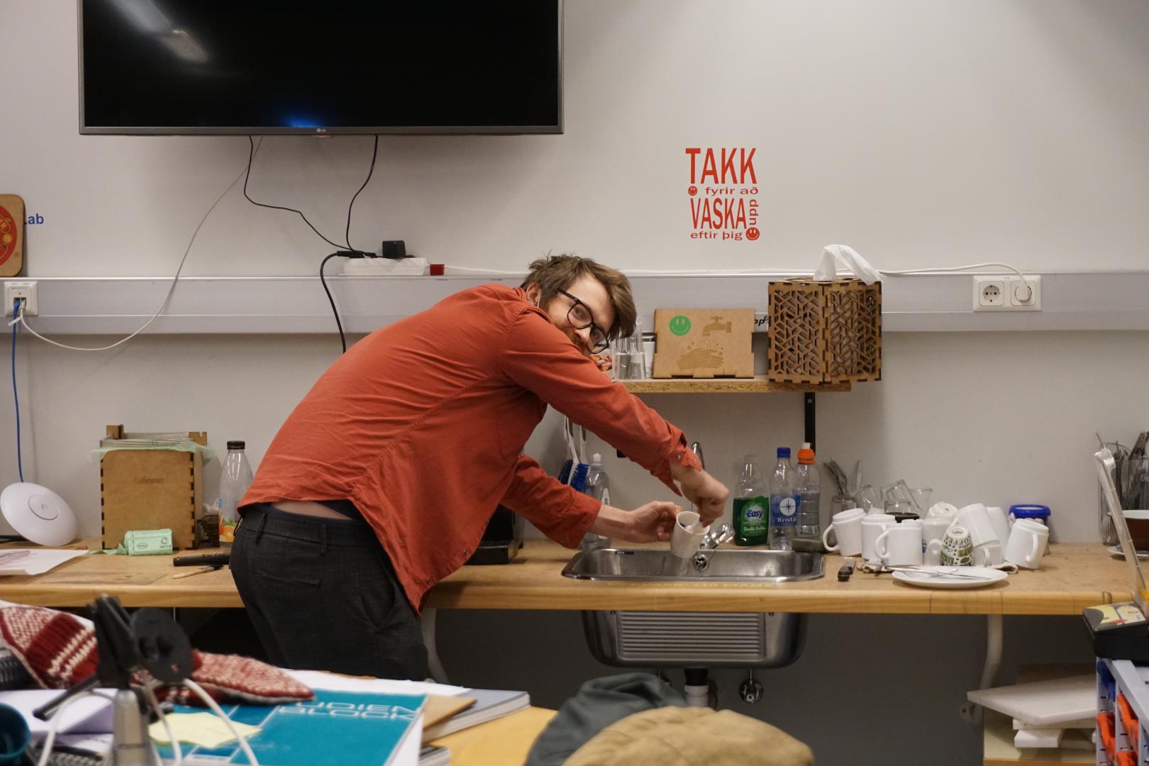
Photographic evidence of the miraculous power of the vinylcutter.
Here my colleague Jón Þór is dutifully cleaning his own cup!
Parametric design
Time to create a construction kit!
I knew I wanted to used a wedged design and possibly a living hinge. I wanted my parameters, to a minimum, to take the kerf, material thickness and number of items into account. Other parameters such as sizes is also nice to include.
They way I figured I’d do this was to input as many parameters in the beginning and going from there. I look at that as a parametric/constrained design, akin to test driven development of sorts.
I aimed to create a rather simplistic design that focuses on the parameters. For example, for the number of wedges, I don’ want to think about how many should be made. I plan to use the pattern tools in Fusion to create the correct number of wedges, based on how many holes are in each shape and how many shapes there should be. This would then simply be exported and arranged before cutting.
First thing first, parameters.
Parameters are awesome! To add parameters to a Fusion360 design, you must first got to: “Modify” -> “Change Parameters”
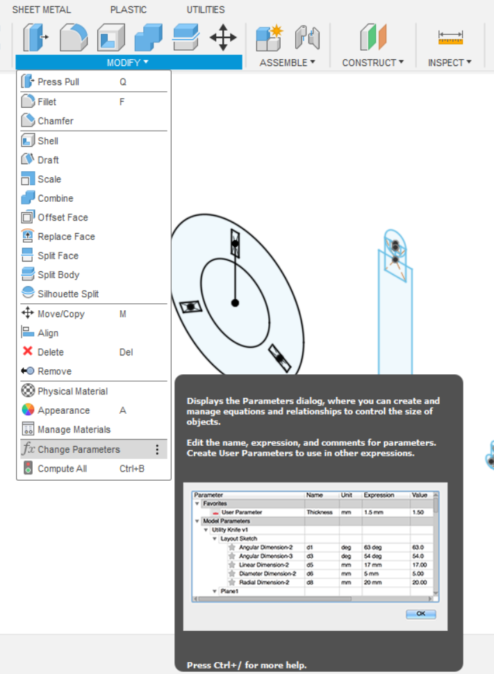
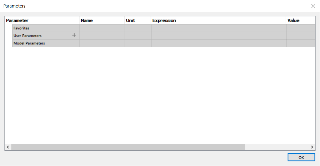
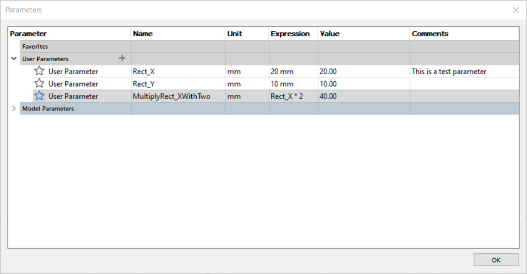
There you are presented with this window where you can select the “+” at “User Parameters” and input your values. Let’s test it out before moving on:
Now we add information to it, making sure the unit of measurement fits your need, there is plenty to select from.
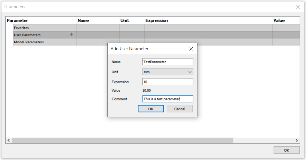
Then just hit OK and..
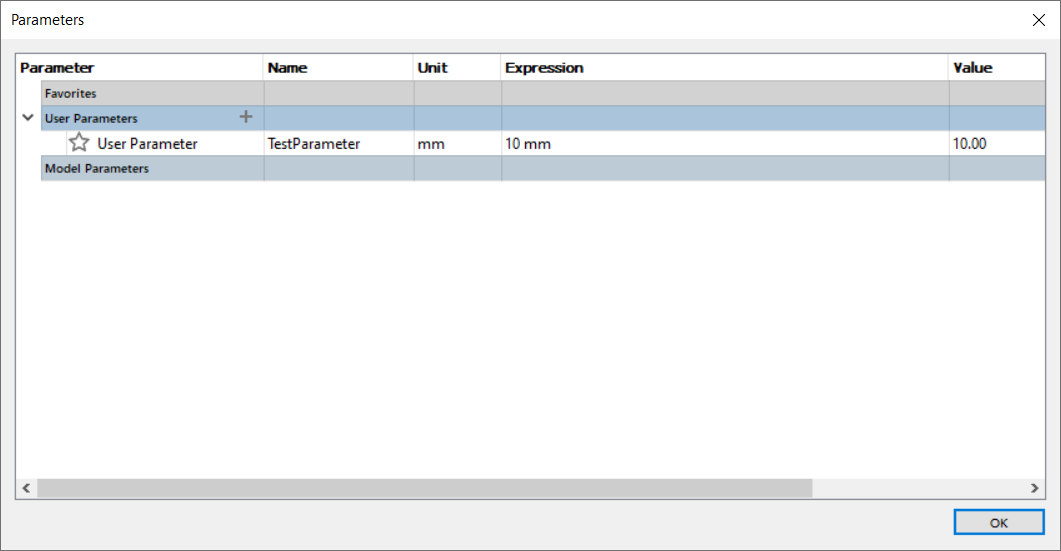
We have our first parameter! Now, let’s try it out.
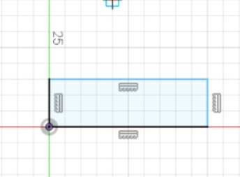
In a sketch we can create a simple rectangle, without giving any special thought to the size of it.
Now we can hit the ‘d’ key on the keyboard (diameters), or select the sketch diameters button at the top tool bar:
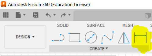
This gives us the option of selecting a part of a sketch and adding dimensions to it. Once an object has been selected, we get an input field:
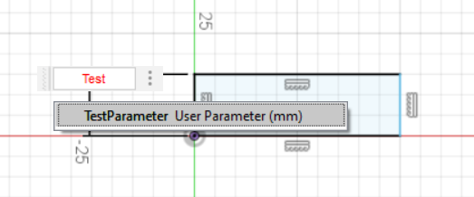
In the field, we can use text search to find our parameters. In this case it’s simple, but if it were a huge project with thousands of parameters, this feature, along with proper naming conventions, is very important.
Adding this parameters to both sides gives us an rectangle of 10mm * 10mm. But here is where parameters come in handy! Based on what my desire is, I can alter this rectangle in different ways, all using parameters.
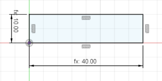
I could, for example, modify the sketch dimension so that the x-axis is “TestParameter * 2”, resulting in a rectangle that is 20mm * 10mm.
In a simple design, this is fine. What would be even better, is to either: - Define the parameter that is to multiplied with, in this case 2 - Define both the x and y of the rectangle, such as adding parameters called “Rect_X” and “Rect_Y” with value of 20 and 10 respectively.
Lets do just that!
Once we have updated the sketch dimensions to use the Rect_X and Rect_Y, we can go back to the parameters table to adjust the values to modify our design. Here I have adjusted the X value to 40. Precise, no clunky dragging or guessing, just parameters!
Moving on
Let’g get going on the this weeks project. Before drawing anything, I added as many parameters I could think of:
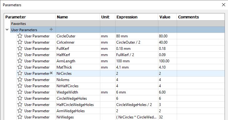
Using only shapes and parameters, I made a simple wedge.
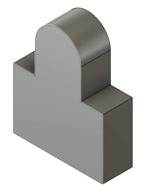
Then it’s simply a matter of creating the pattern. I used spacing as Distance Type to make sure they do not overlap. I also made it so that it expands only in one direction, so adding other shapes to automatically expand below would not be a problem.
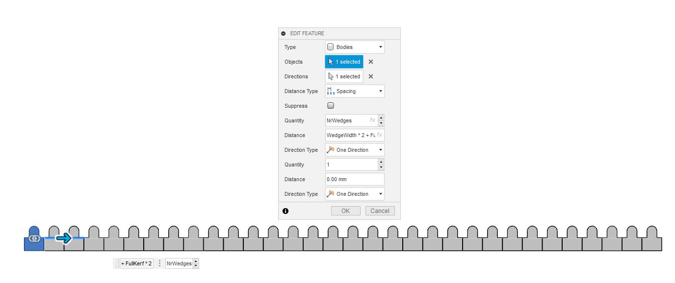
Beautiful!
More shapes
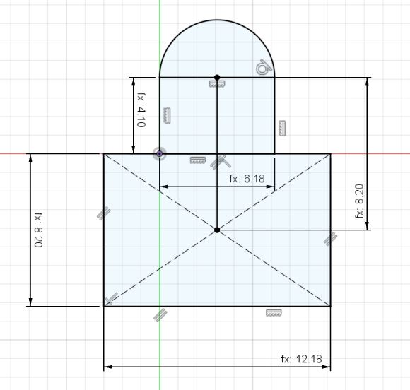
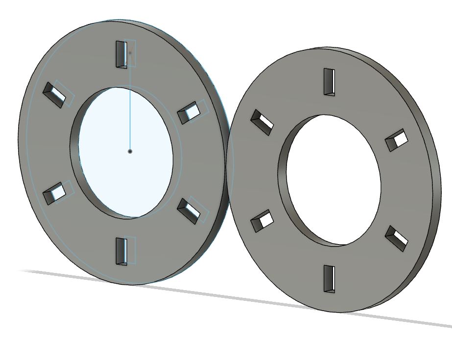
Next up, circles and half circle!
Creating the circle was simply a matter of inputting the parameters with the circle tool, then creating the wedge hole pattern.
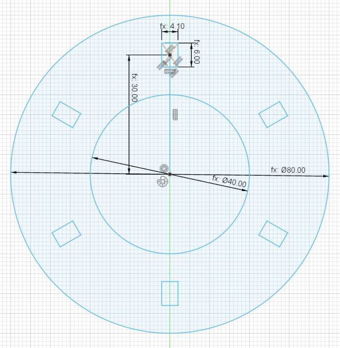
Extruding and adding a repeating pattern!
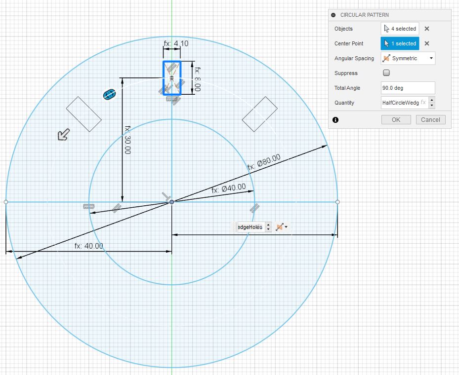
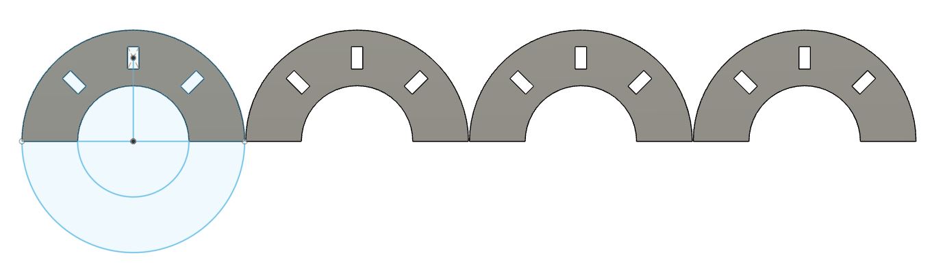
Next up, half circle. This called for a bit of testing of settings, but thankfully, fusion has the proper tools to address this. Because it’s a half circle, I need to fix the degrees of which the circular pattern can expand to. For the half circle, I used the symmetric setting along with 90°, thus creating the half circle working area as needed.
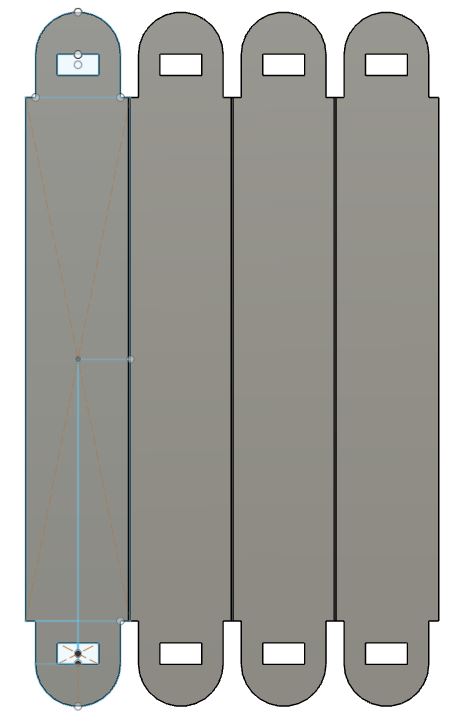
The arm
Now, the arm. First I created the arm and the pattern to multiply it.
OH-NO! Brainfart!
Just then, when rubber ducking design with my colleague, I realized that I had only made holes of the size of wedges but nowhere to insert the arms! Luckily, the design is parametric so the fix was not that hard.
I first added a parameter for the ArmHead, updated the parameters on the circles and then the arm. Voila, fixed!
Just before I got way ahead of myself, I added a sketch, projected a couple of items and cut them.
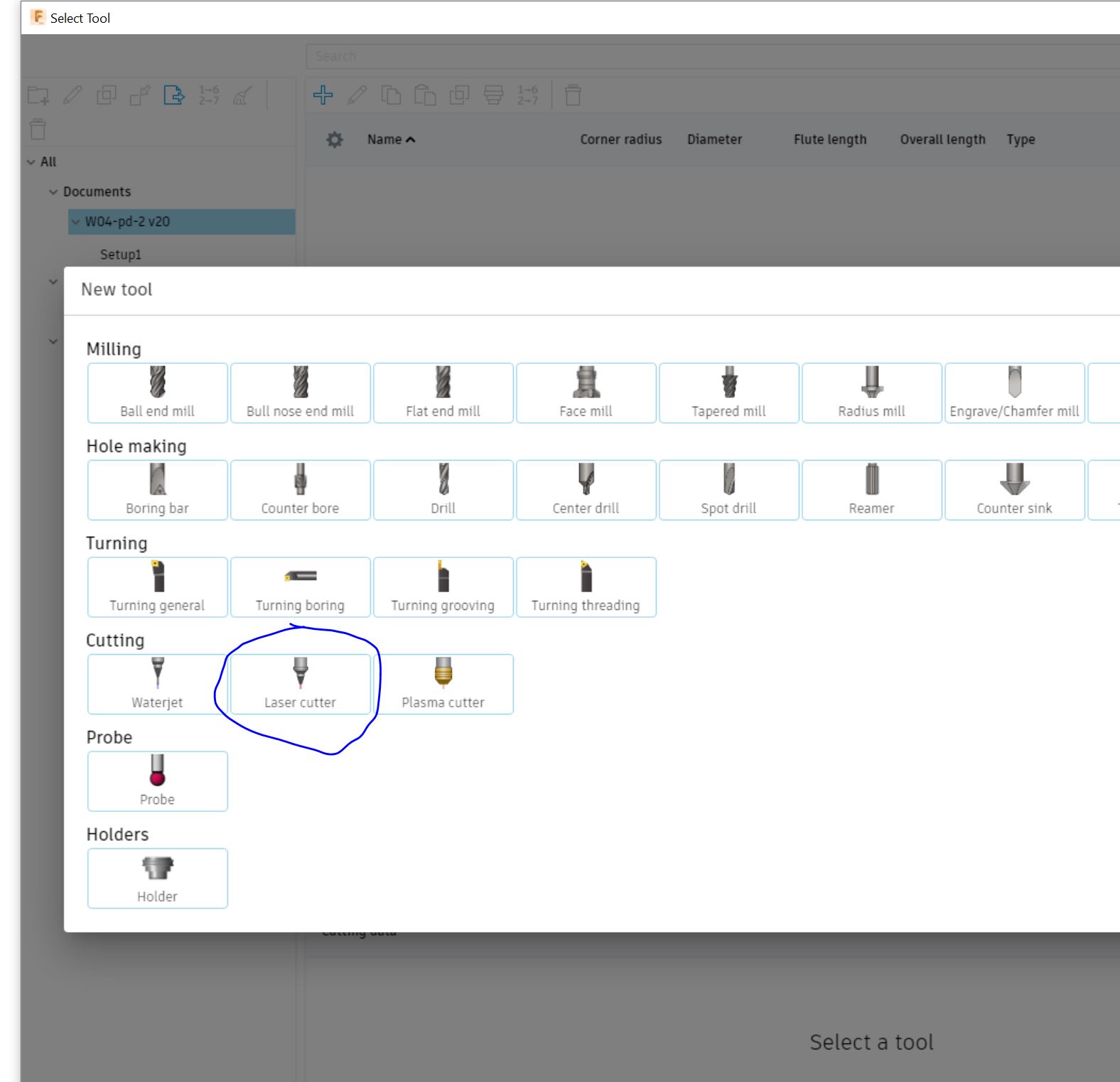
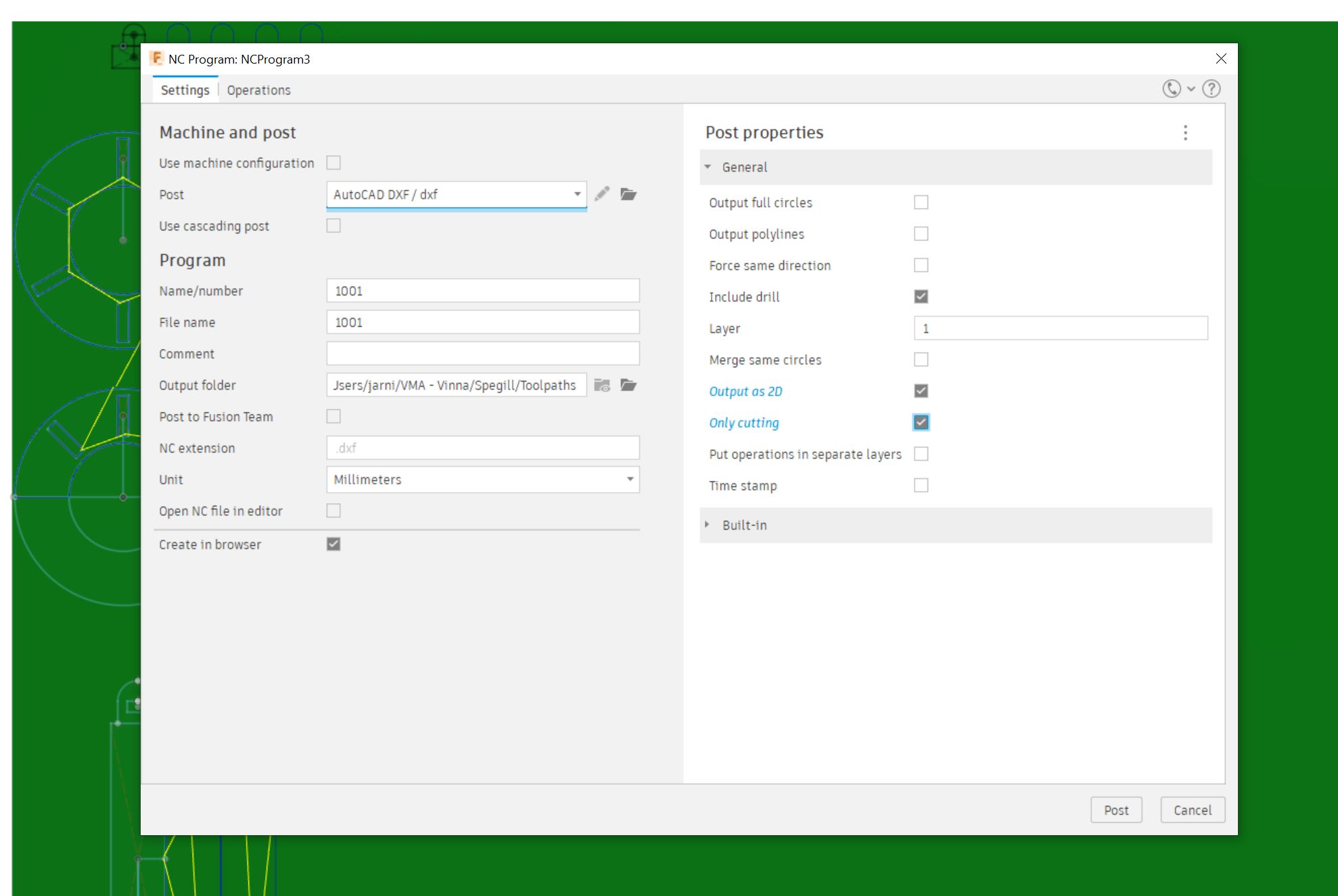
When I tested the objects, I found out that I had made kerf errors. I had mixed up adding and subtracting the kerf, so to eliminate these goofball errors, I used the power of Fusion 360 to manufacture and post-process the objects. That way I can add the kerf to the tool library, select the object to extrude and get a properly setup file to cut out.
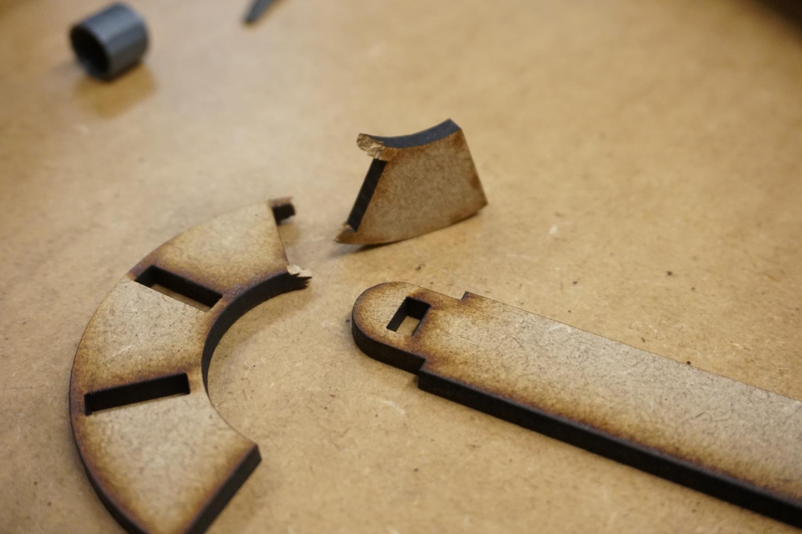
I removed the kerf parameters from the design, added the laser tool profile and manufacture a part of the design. This resulted in a .dxf that I imported into Inkscape and then cut. They were so snug that I instantly broke the circle.
Then the first thing I did was to break the circle! It’s very snug and there was just not enough material for strength.
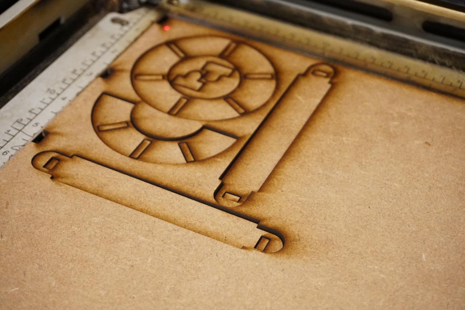
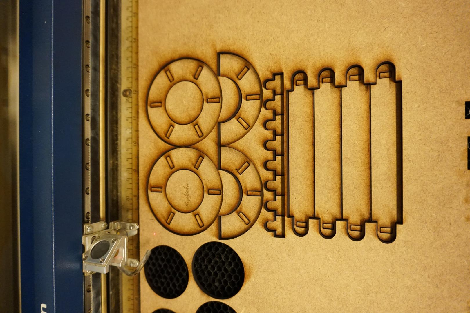
Adjusting the parameters is so much easier than dragging and messing up the design constantly! So I did just that and cut a complete kit.
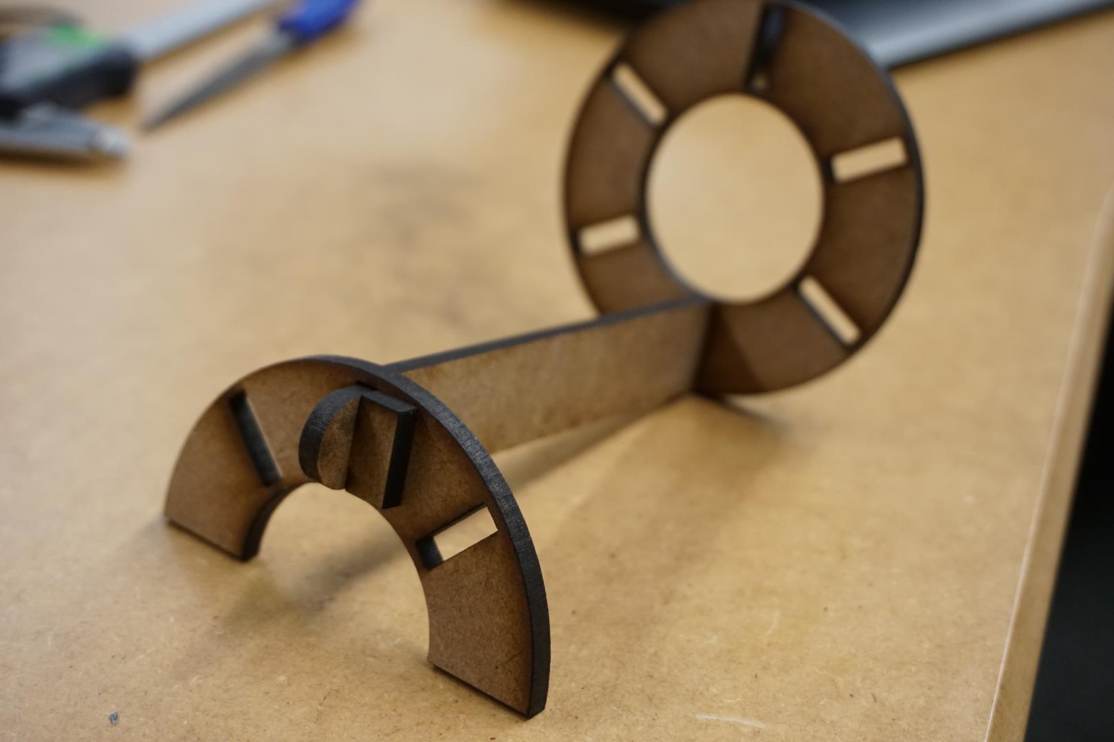
Complete kit
After making adjustments and generating a file, I tried out Deepnest.io. It’s a neat tool to minimize the waste of materials.
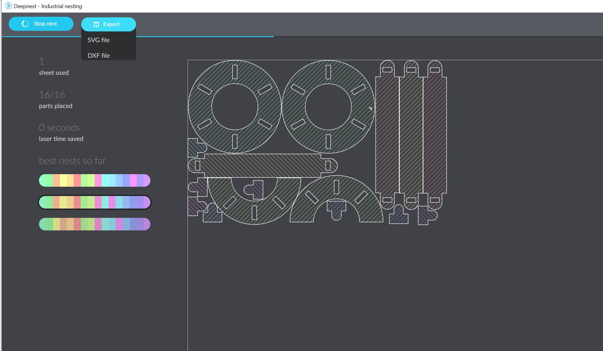
But I ran into the issue that somewhere in the process of importing and exporting files between programs, the scale was off. So I ended up simply lining things up by myself and cut it.
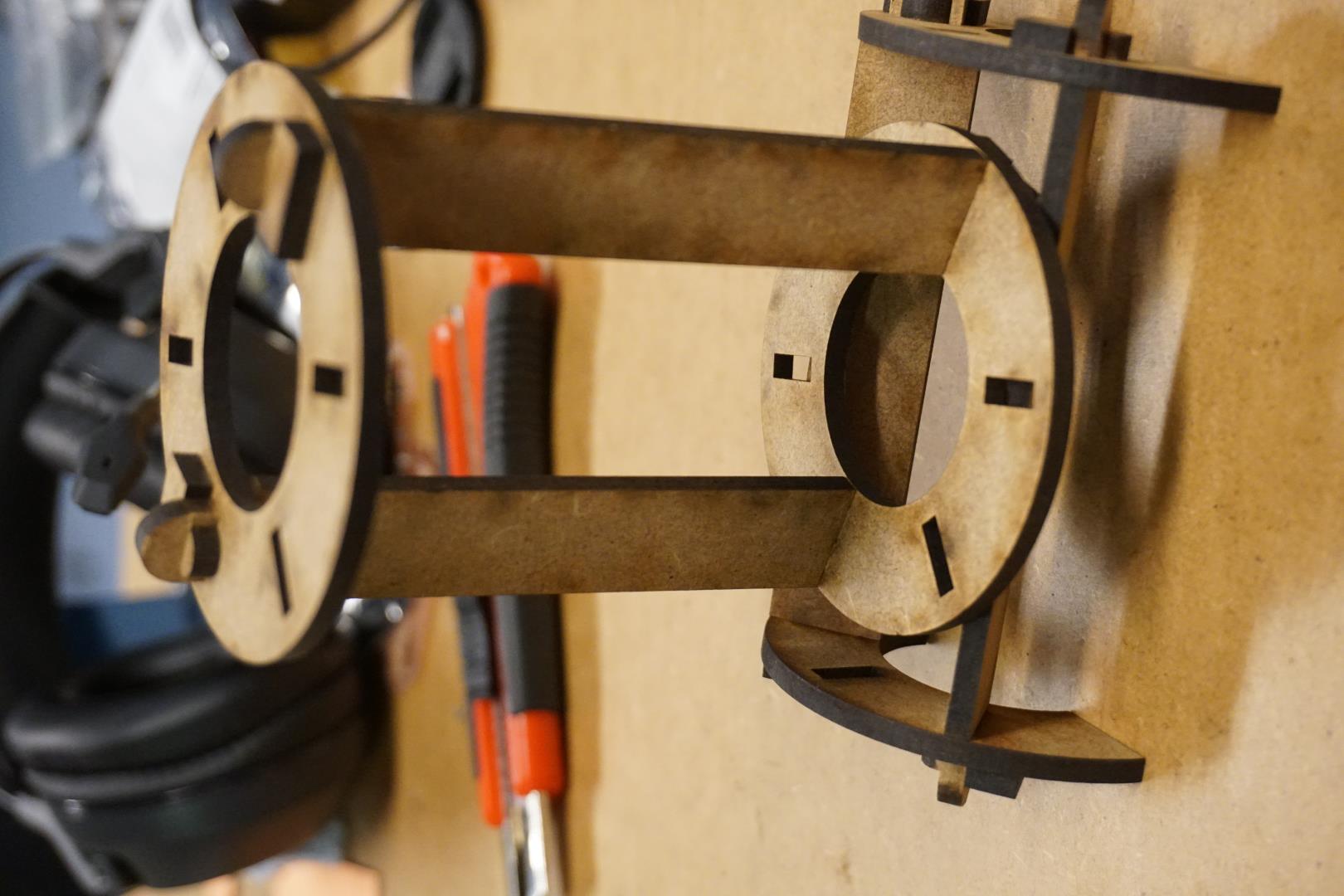
Parametric design ftw!
Conclusions
-
The thing I kept thinking about, but could not carve out the time to properly investigate, was the idea of error handling of sorts. What can I do to limit the amount of silly inputs from the user? Maybe this is not something I should be considering, but coming from a CS background it’s pretty ingrained in my mind.
-
I need more exercise in parametric design, but the concept is brilliant.
-
The design is not perfect, but it’s a good start.
This weeks files
| Sticker files |
|---|
| Mana |
| Really? |
| Laser character files |
|---|
| 10 mm boxes |
| 10 mm boxes updated |
| Joint |
| Ten |
| Parametric files |
|---|
| Video |
| Fusion file |
PS: Image resize on Windows
I wanted the ability to batch resize images with right-clicking and found these beauties: PowerToys. I now a have a option for resizing images in the right click menu. Wonderful!
PPS: Git fail(s)
Fail #1
I just ran into my first git fail, which slowed me down a bit. I accidentally pushed a full sized image from my DSLR.
This caused the following error in the terminal:
remote: fatal: pack exceeds maximum allowed size
error: remote unpack failed: unpack-objects abnormal exit
remote:
remote: ========================================================================
remote:
remote: stdin send error: EOF
remote:
remote: ========================================================================
remote:
! [remote rejected] master -> master (unpacker error)
It’s a size error but I looked to the Mattermost chat for a bit of guidance. Julian confirmed that it’s related to the size of the commit and pointed me to a interactive rebasing.
I found this guide helpful.
So the steps I took to fix the error were:
git reset --soft {sha-1 ID of the commit}git rm --cached {filename}git commit --amend
Then I then added the resize photo again, using the normal git add, commit and push.
Hope this helps somebody!
Fail #2
I broke the pipeline! When adding the video above, I wanted to follow instructions to embedd the video instead of hosting it elsewhere. I recorded my screen using OBS and wanted to use this plugin for embedding the video. I found mkdocs-video and installed per the instructions. What had not registered with me was that I had to update the requirements.txt file. Quickly finding the version, by scrolling back in the terminal, I added the follwing line in the requirements.txt file: mkdocs-video ~= 1.1.0
Then I commited and pushed, the pipeline was fixed!
What a joy!
Additional notes
Possible further imporvements
Let me be the first to admin that the construction kit is not the worlds most perfect set.
My main idea was that it would be easy to create multiple objects using the parameters and the program would automatically generate the correct number of wedges.
A couple of things to imporve:
- Adding more holes to the items, so they can be assembled into more complex shapes.
- Adding more diverse shapes to the kit