16. Wildcard week
My self-assigned assignment for the week is:
- Learn to use the plasmacutter in the school metal shop
- Document it’s usage for this site
- Document it’s usage for teachers and students in the school in our native language.
Reasoning
The plasmacutter is a computer controlled tool that is used to cut sheets of metal. You can think of it as a massive lasercutter, working with 2D designs, that can cut:
- Mild steel
- Stainless steel
- Aluminium
It is used heavily in production and prototyping all around the world. So it’s a great tool to learn to use.
Documenting it’s usage properly, especially in our native language, for the teachers and students will be big help in the future. For me and the Fablab, it would greatly expand our capabilities.
Design
For this assignment and the purpose of creating accessable instructions, I want to keep the design simple. I’ll be designing numbers to put on the exterior of my house.
For this I’ll use Fusion 360. There is nothing stopping you from doing this in Inkscape or other tools, anything that is able to export a proper dxf file.
My house is Nr. 16. I’d like them to be seperately mounted on the wall, so there will be two pieces. For that, I will create two sketches, one for each number.
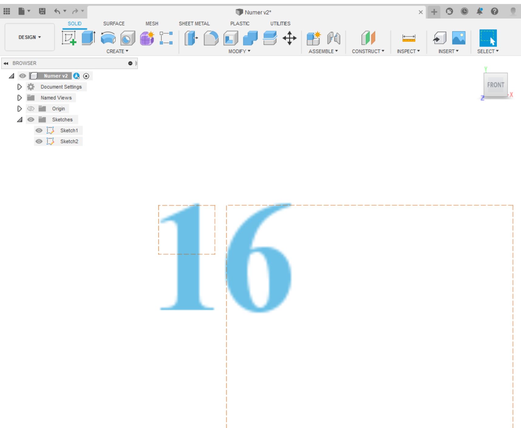
I export each sketch as a DXF to a USB drive. Right click the sketch and select Save as DXF.
| Design files |
|---|
| Letter: 1 |
| Letter: 6 |
Plasmacutter
The machine
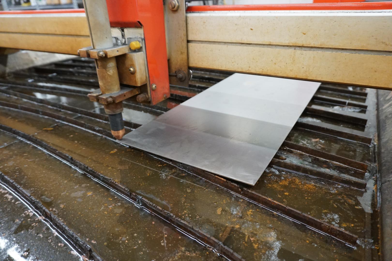
The plasmacutter is made by Swift-Cut. It is approximately 3 meters long, and 1.5 meters wide. There is a metal grid to lay the sheets on with a waterbed below which extinguishes sparks and molten metal.
Plasmacutters works by sending pressurized gas through a small channel. In the center of that channel there is a negatively charged electrode. When power is applied and the tip touches the metal, a spark is created. This powerful spark heats the gas so that it reaches the fourth state of matter(plasma). This plasma is super hot (~16.000°C) and moves extremely fast (6000m/s) which melts the metal and blows it away. Hardcore stuff!
Different gases have different effects on the cuts. Oxygen is cheap and works well with mild steel while other gases such as nitrogen, argon and hydrogen are also used. They have diffrent properties what I will not dive into here, since our machine is not equipped with any of these gases.
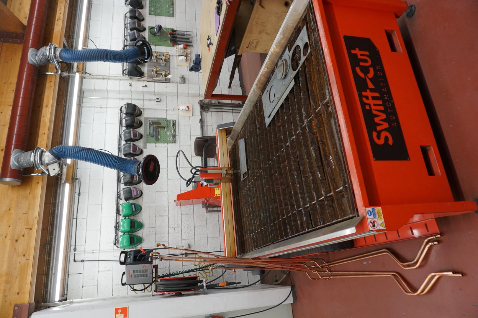
On this picture, you can see the bed clearly. In the center, there is the plasma cutter head, which moves around the bed. Behind that is the computer that controls the plasmacutter, in the red stand.
On the top left, mounted on the wall, is the actual plasmacutter. Please also notice the air-venting system, which is important!
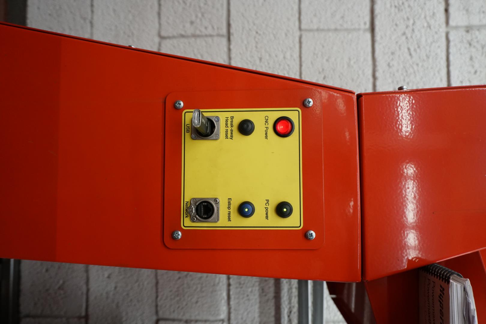
On the computer stand, there is a control board to start the computer, engage power to the machine and to engage the control movement mechanism.
You also see a clear violation of protocols, DO NOT STACK ITEMS ON PLASMACUTTER!
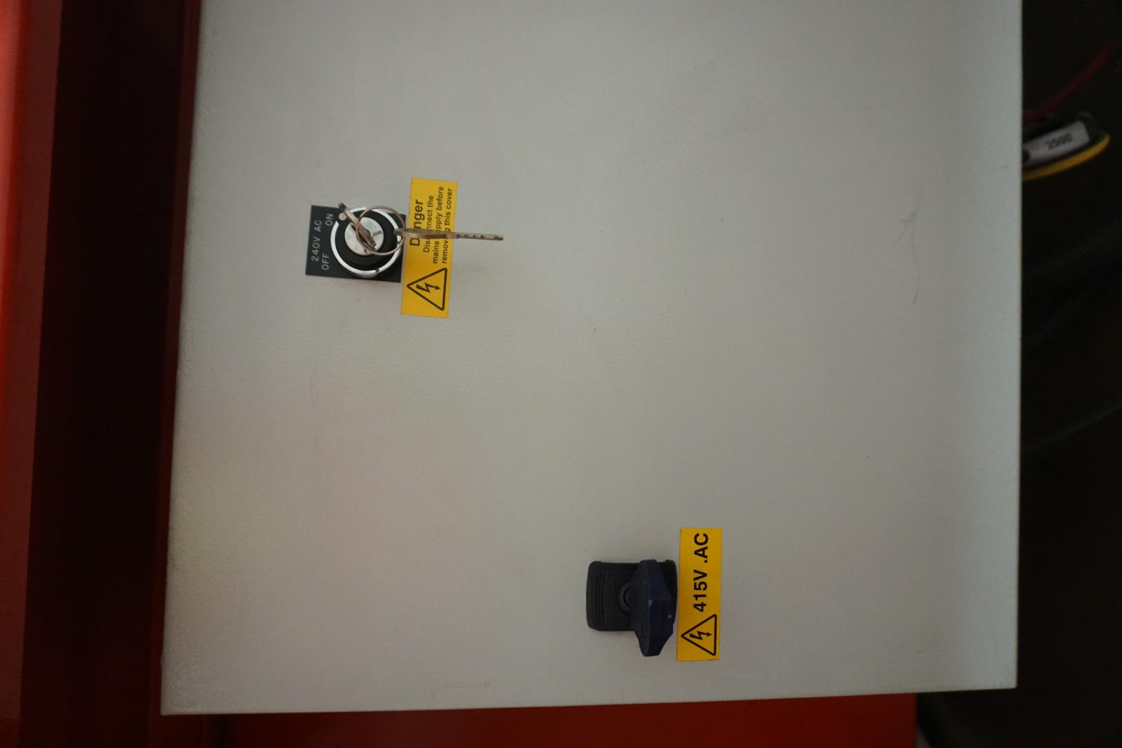
There is also a keyed powerswitch to power one the plasmacutter.
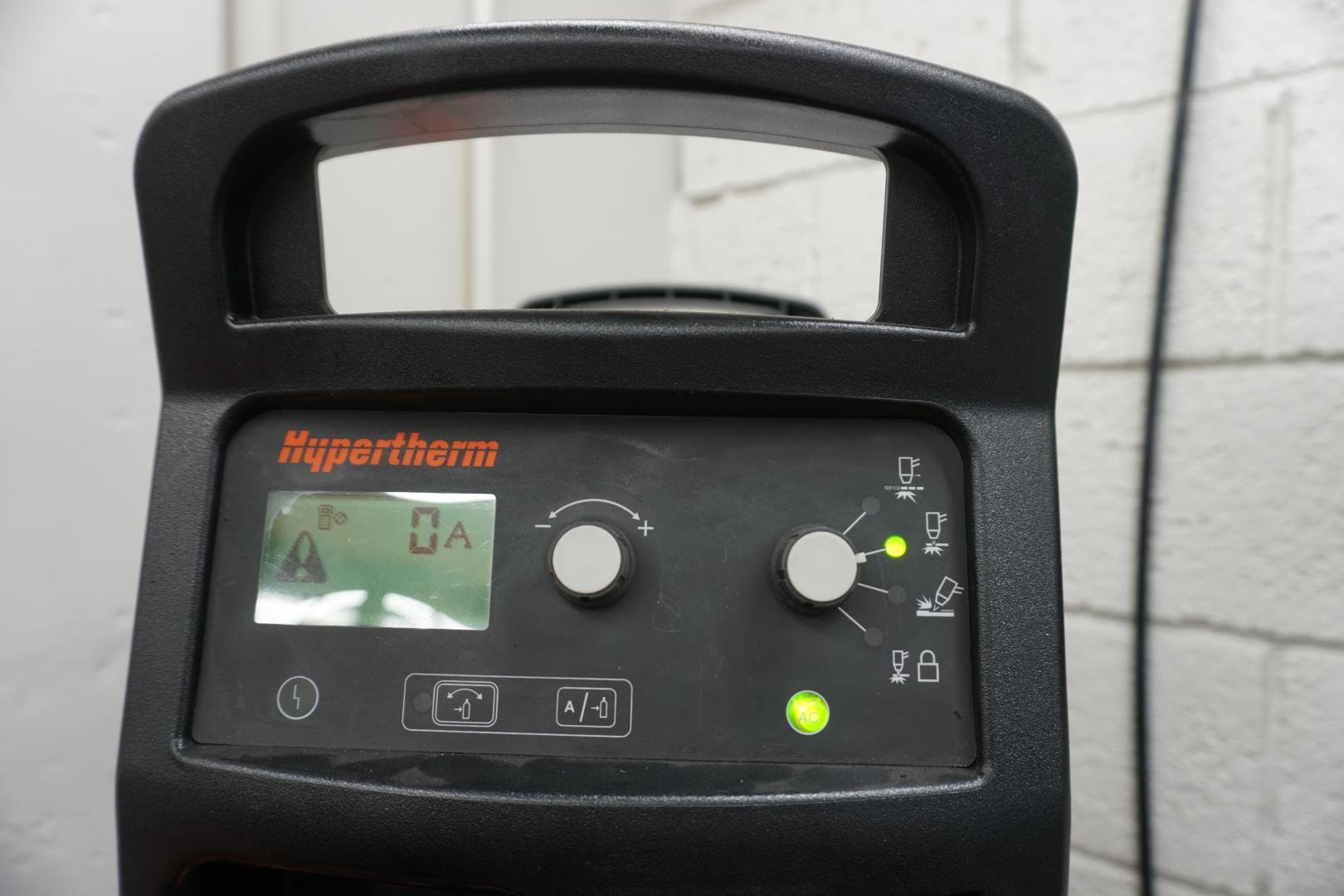
The plasmacutter is named Hypertherm. It has a button interface with a display screen. This device is connected to the computer via ehternet cable and is controlled by the computer. All we need to make sure is to adjust the know on the right to the correct settings. Here we are only covering cutting of metal, which the know is set to.
It can also be used to mark metal and pierce it.
Settings of gas pressure and amperage is controlled by the computer.
The interface
We now turn on the computer and are presented with this screen:
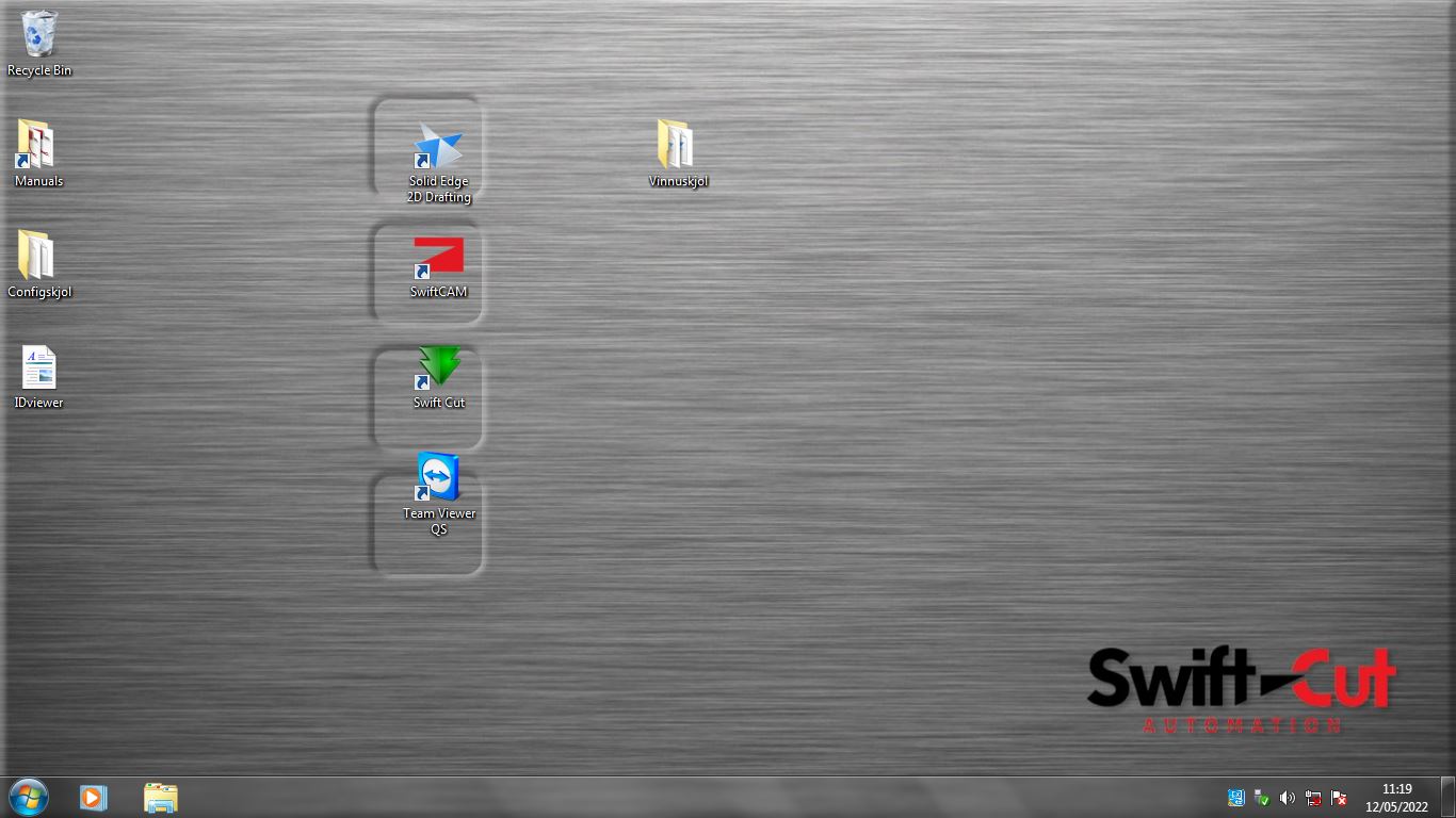
There you can see three diffrent tools which are related to the cutting:
- Solid edge 2D Drawing: Can be used to create a cutting pattern.
- SwiftCAM: To turn drawings into cutting jobs.
- SwiftCut: To load the jobs and interface with the plasmacutter.
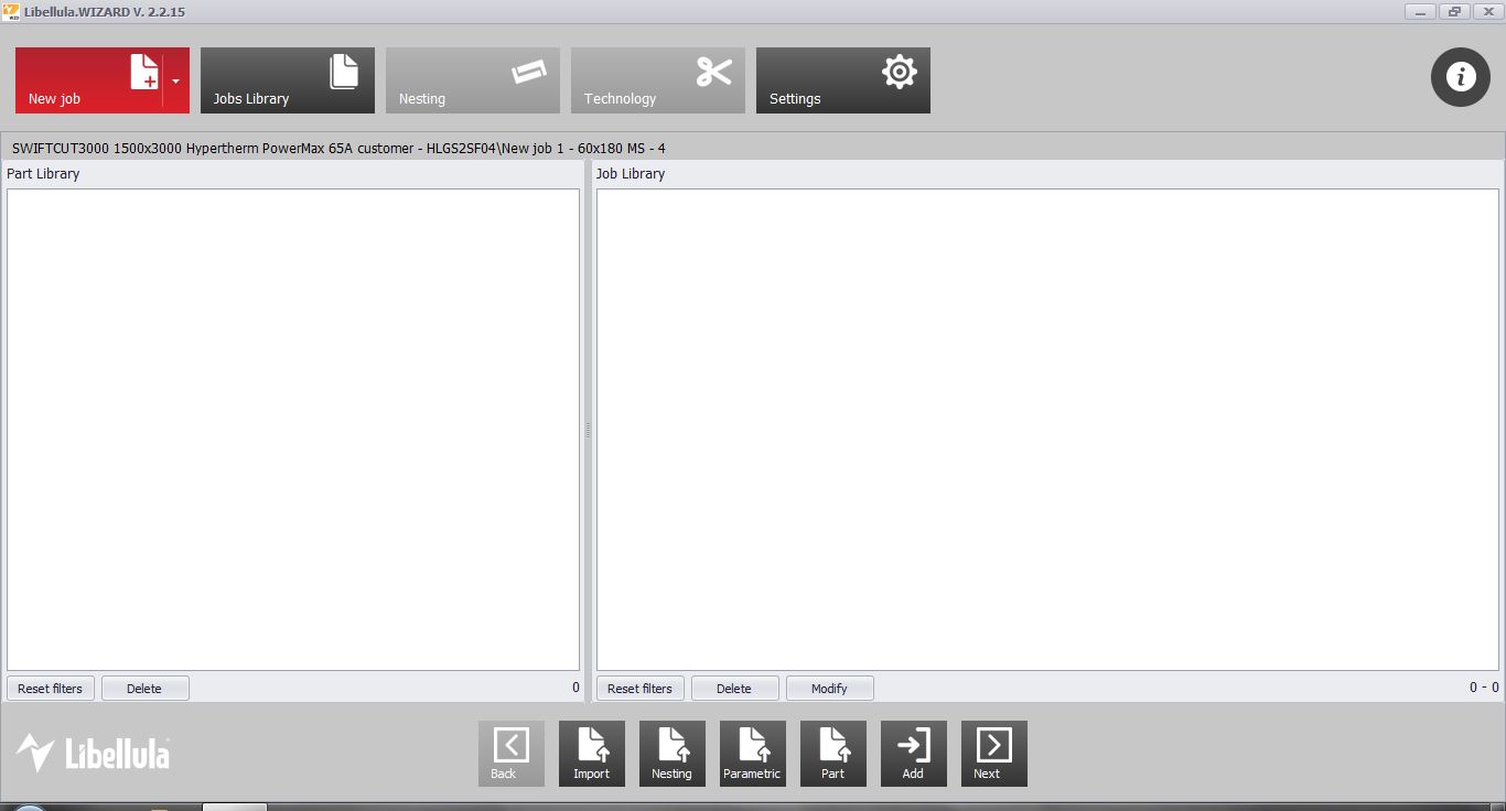
Generating the job
As we have our drawing, go directly to SwiftCAM.
We create a new job, provide the information needed. I’m using a scrap piece of stainless steel and I need 130mm x 300mm. (Screen shot was taken with wrong input).
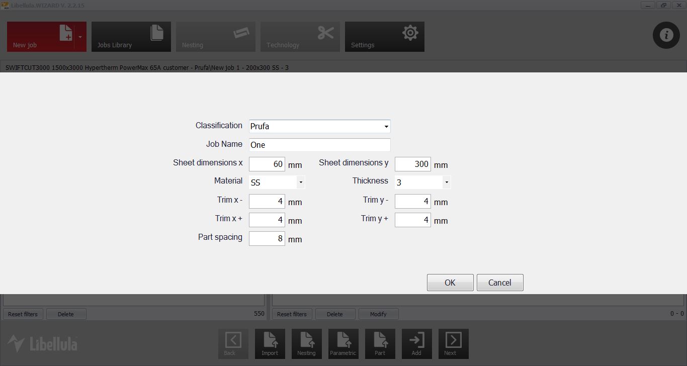
Material: SS (stainless steel) Thickness: 3mm
Trim and part spacing are constraints for placements of the parts.
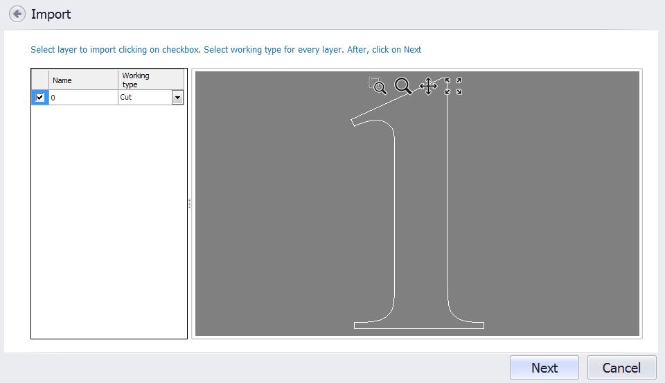
Here we see a preview of our drawing but we can select different operations under Working type. We are going to cut it out, so we select Next.
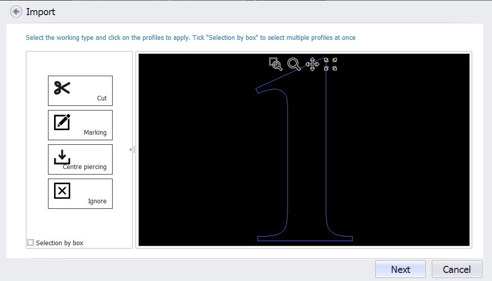
Now we are in the cutting profile settings. Outlines are displayed in the preview. We have different options to the left but what is important here is that the lines in blue will be cut. You can use the Ignore option to de-select lines. Ignored lines will not be cut and are white in color. Again we select Next.
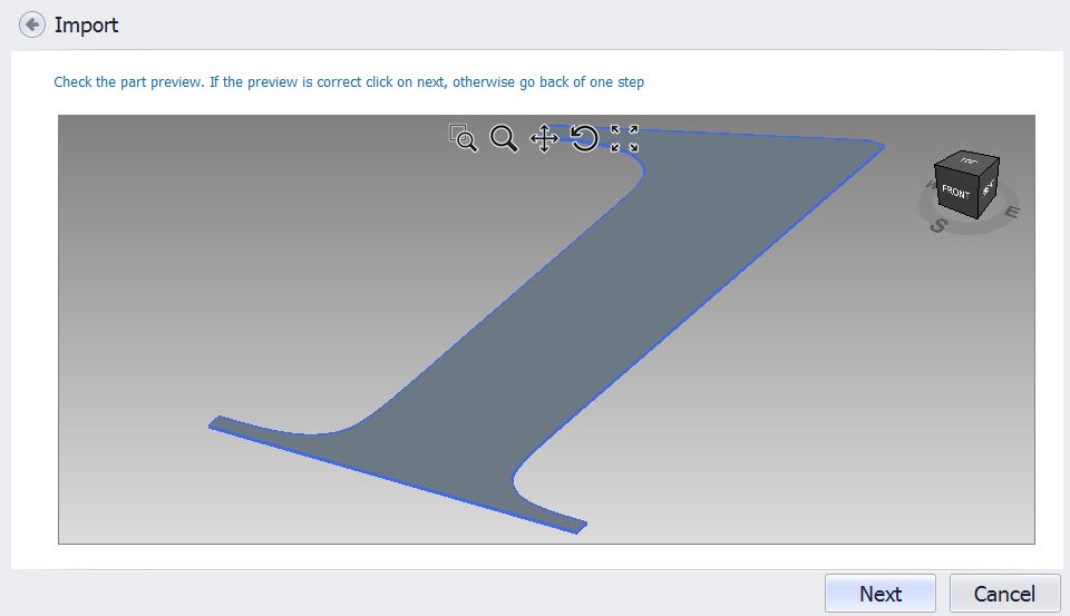
We are presented with a 3D preview which can be good to identify any troubles.
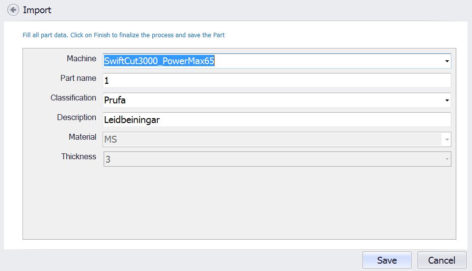
Next thing to do is to save the job. The machine is already set up, we must provide a part name, classification and a description. Then we hit Save.
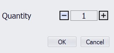
We are asked to provide the quantity we want. I’m only going to cut one piece, so I set it to 1. For manufacturing, you could set this to a much higher number which you would then need to place in the next steps.
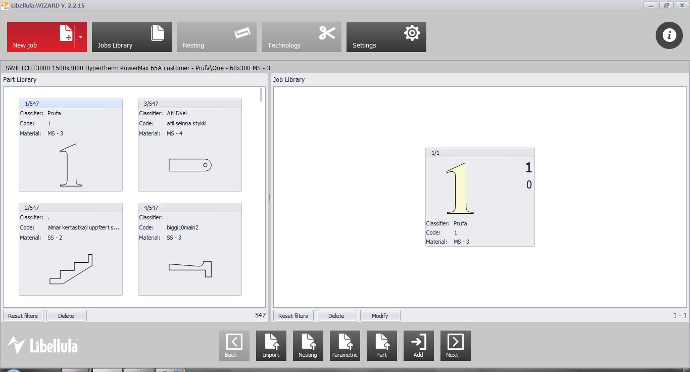
Now the job is saved and we need to place it on the cutting material. We hit Next.
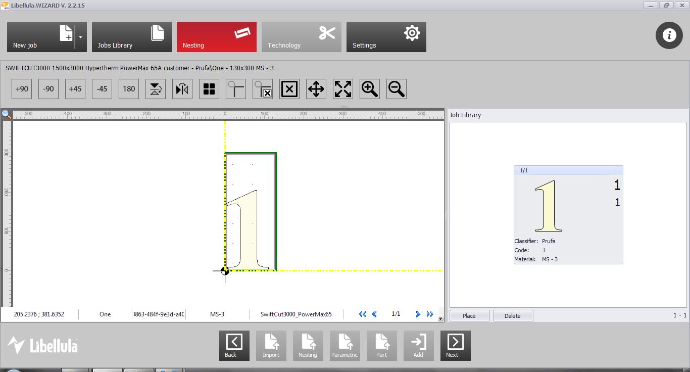
It fits well and we hit Next. If the piece would not fit, we would need to scrap the job and start again with correct dimensions (Exactly what I had to do!).
On the next screen, we a presented with this toolbar.
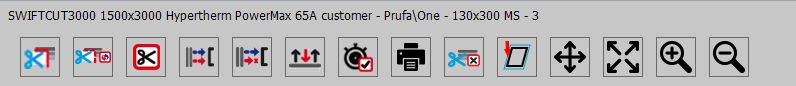
What I must now do is to select where the cutter will start. This is called Lead-in. The tool to furthest to the left is called Add lead-in. Select that, click on the design where you hant the lead in to happen. You can adjust the A and B values, which are the distances from the edge of the part to the edge of the cutter, where it will start(A) and where it will end(B). These values are fine for us, but might need adjustments for other machines or materials.
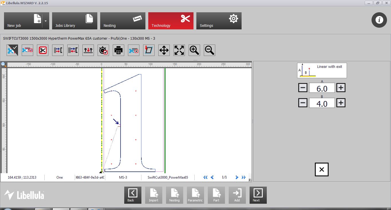
Once happy, we select Next.
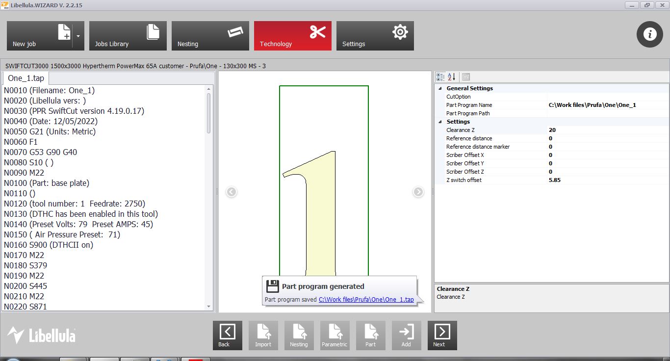
We are now presented with this view and the statement that a part program(job) has been generated.
Cutting program
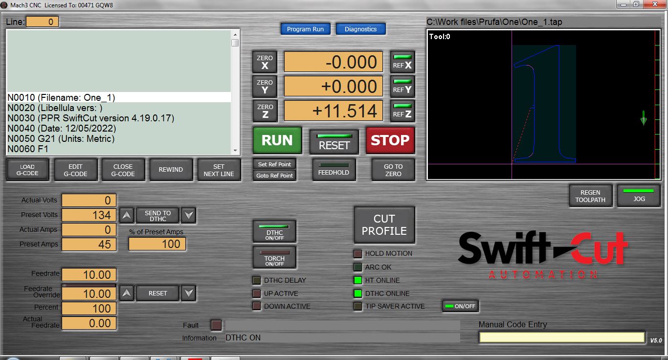
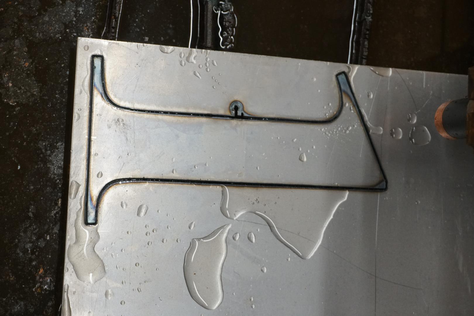
Next we start up SwiftCut. This is it’s main interface.
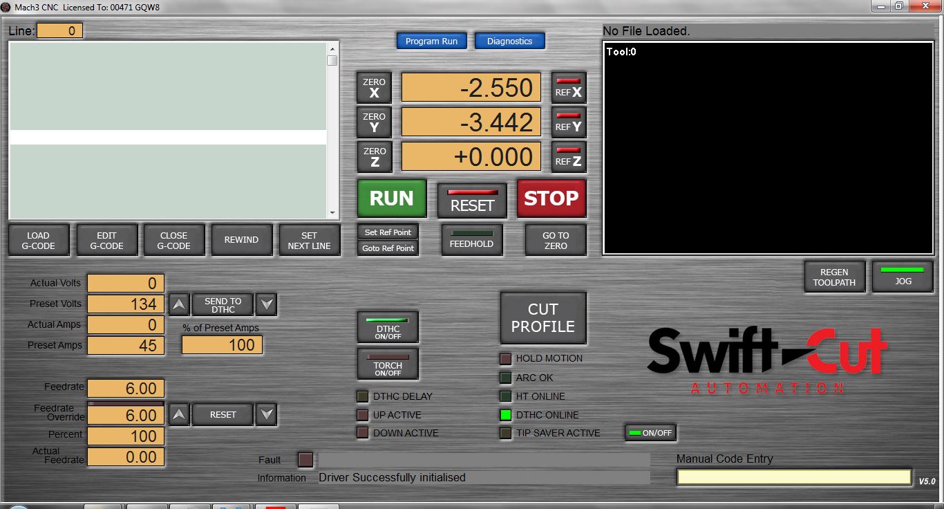
We can move the plasmacutter head with the arrow keys, Z axis is controlled with page up and page down.
In the middle, you can see X,Y,Z coordinates. We need to make the machine refrence it’s coordinate system. We can do this by selecting selecting REF X and REF Y. Make sure the bed is clear and the height is clear. It then moves the x and y axis to the edges and gets it’s location reference.
You can see that the REF X and REF Y now green (the values are that way because I moved the head before taking the screenshot, otherwise the values would be zero).

Next we need to zero the Z axis. I move the head so that the plasma head will touch on top of the plate, where it has back support. It pushes down on it with quite some pressure, so it must sit firmly otherwise the measurement will be bad. We hit REF Z, the machine does it’s thing and the Z axis is now green!
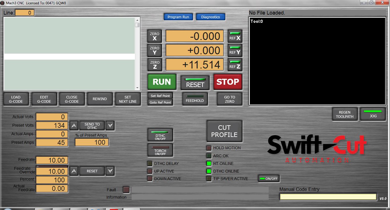
Then we zero the values for X and Y relative to the material to be cut. Move the head to the lower left corner of the piece and press Zero X and Zero Y.
All set to move on!
Load GCode
Now we can load the G-Code file. Select Load G-Code and open the generated file.
Cool! We are almost ready! Make your you are wearing appropriate PPE, such as goggles, welders helmet, gloves, steel toe shoes. Also turn on the air suction!
Then we are ready!
Press Start!
It’s extremly fun to watch, but make sure to be ready to hit the stop/emergency stop button if anything goes wrong. We are dealing with heavy machinery here!
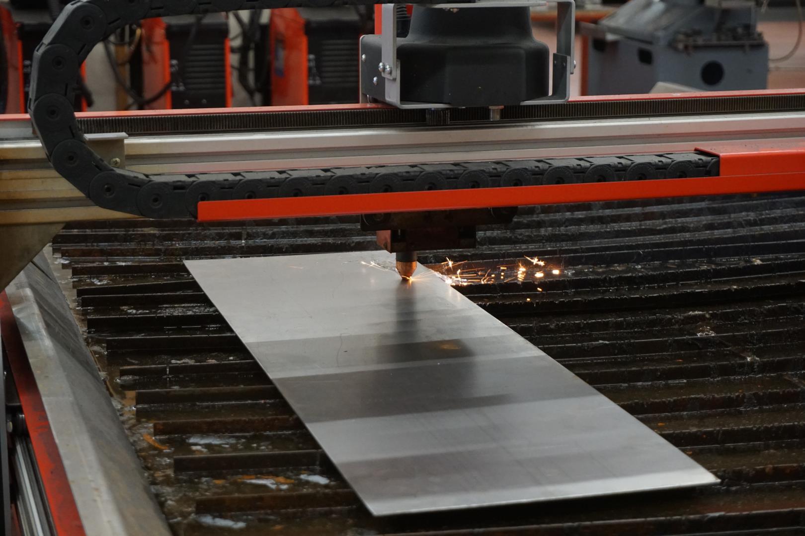
The job finished well and I quickly loaded the next part to cut.
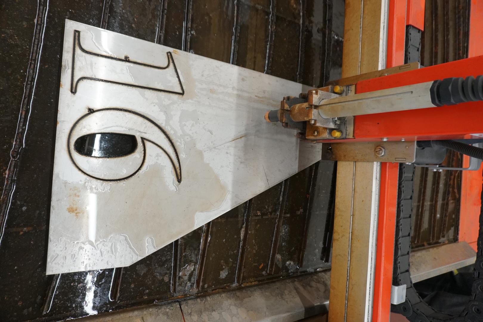
Extra notes
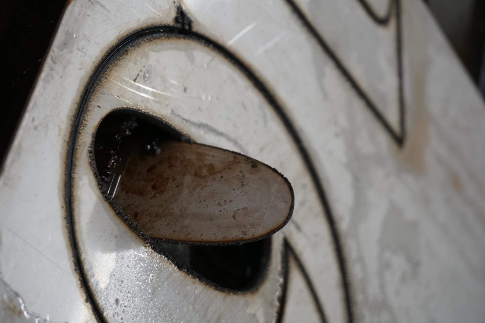
When adding the lead in to the second part, which contains a inner part to cut, there is some thinking and attention required!
It’s not smart to cut the outer part before the inner part, because it might move, ruining the project. You must also be on the lookout for parts that might come loose, fall halfway through the grid and stick out. This might cause the cutter to hit it, potentially causing damage.
Documentation
Above I have documented the steps needed to cut out your own design using the plasmacutter.
I will make these instructions make due here, since the one I write in Icelandic will probably not be very helpful for you! =)
Have a nice one!