Networking and Communications
Project description
Group Assignment
Send a message between two projects.
Individual Assignment
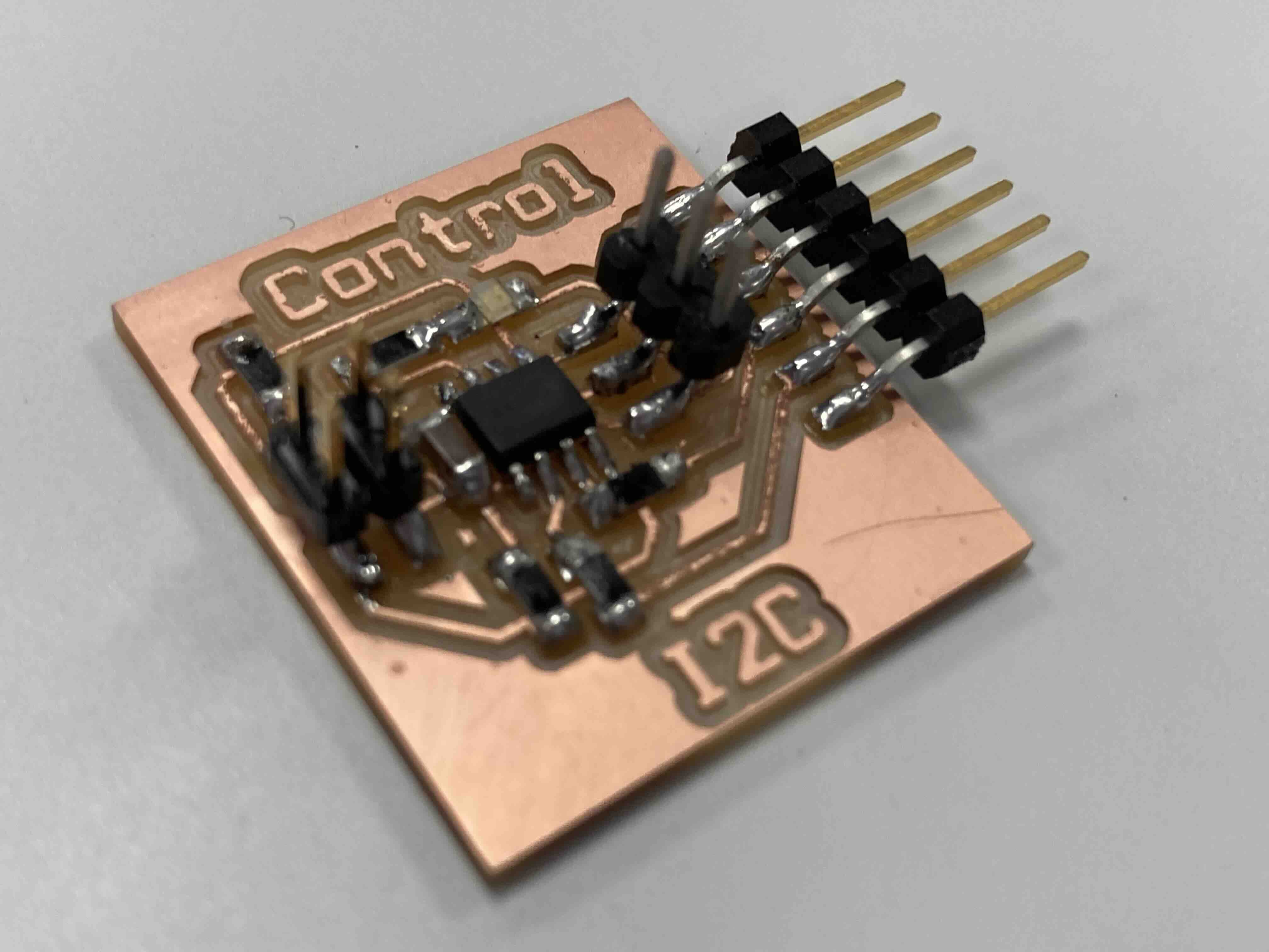
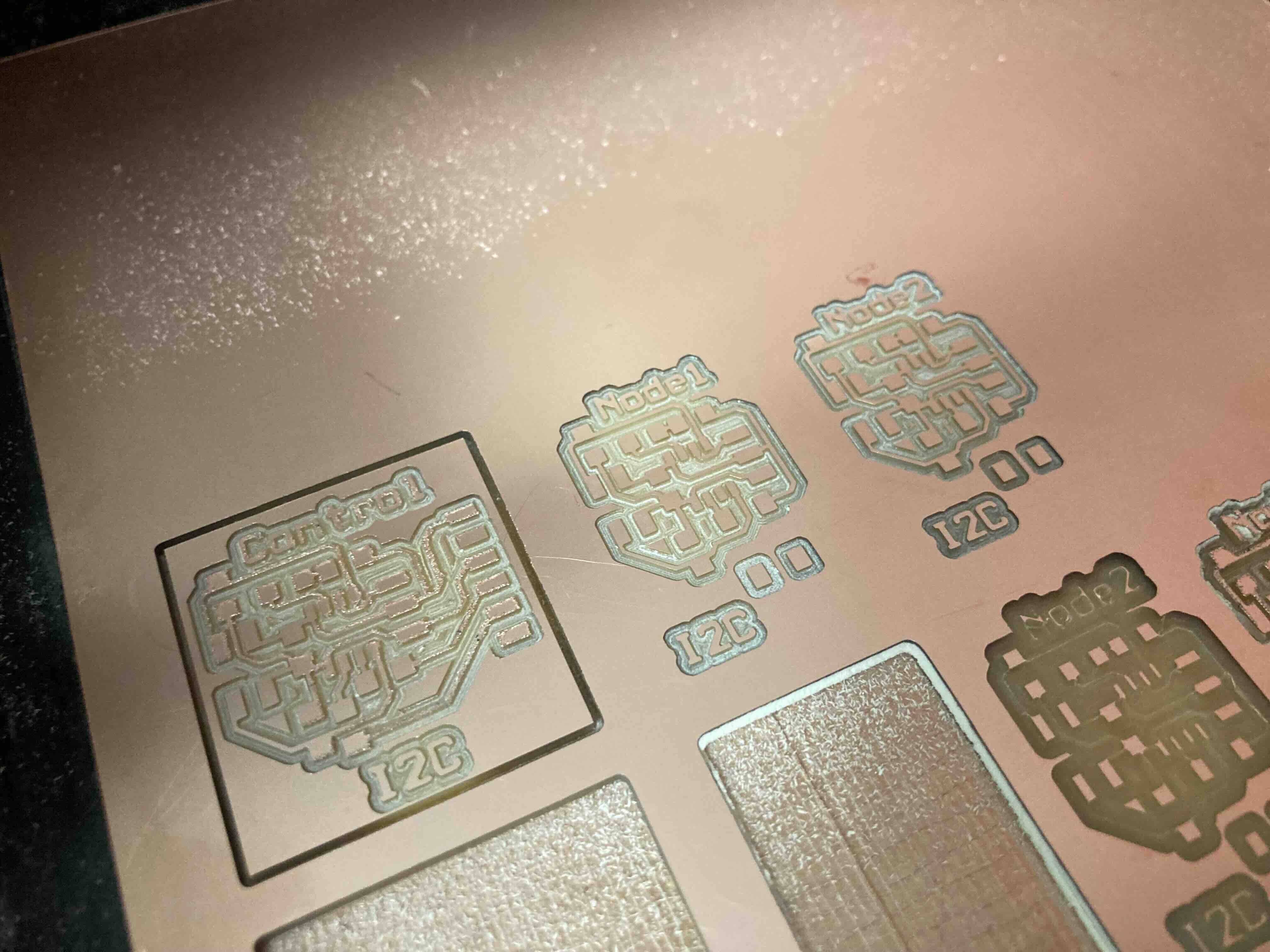
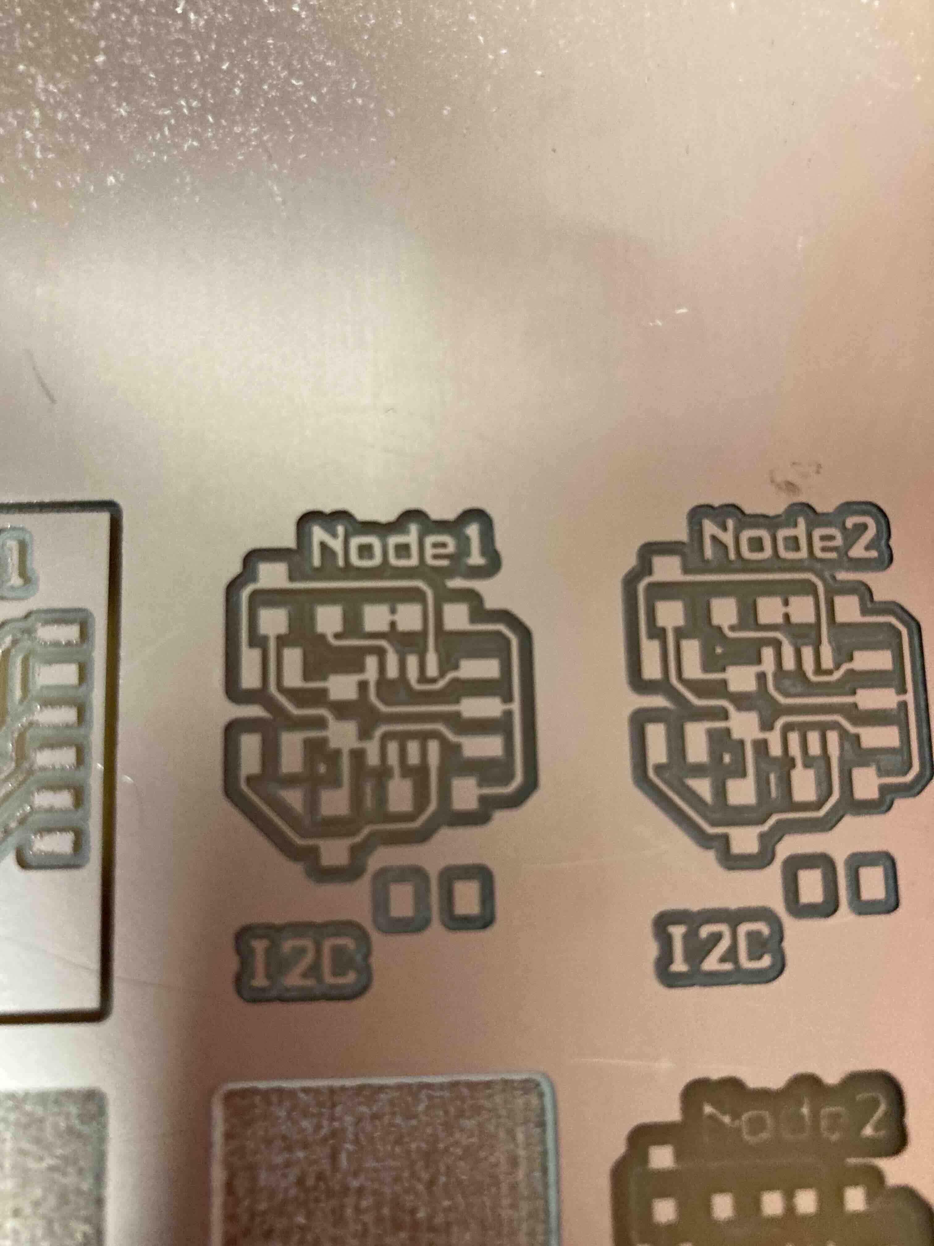
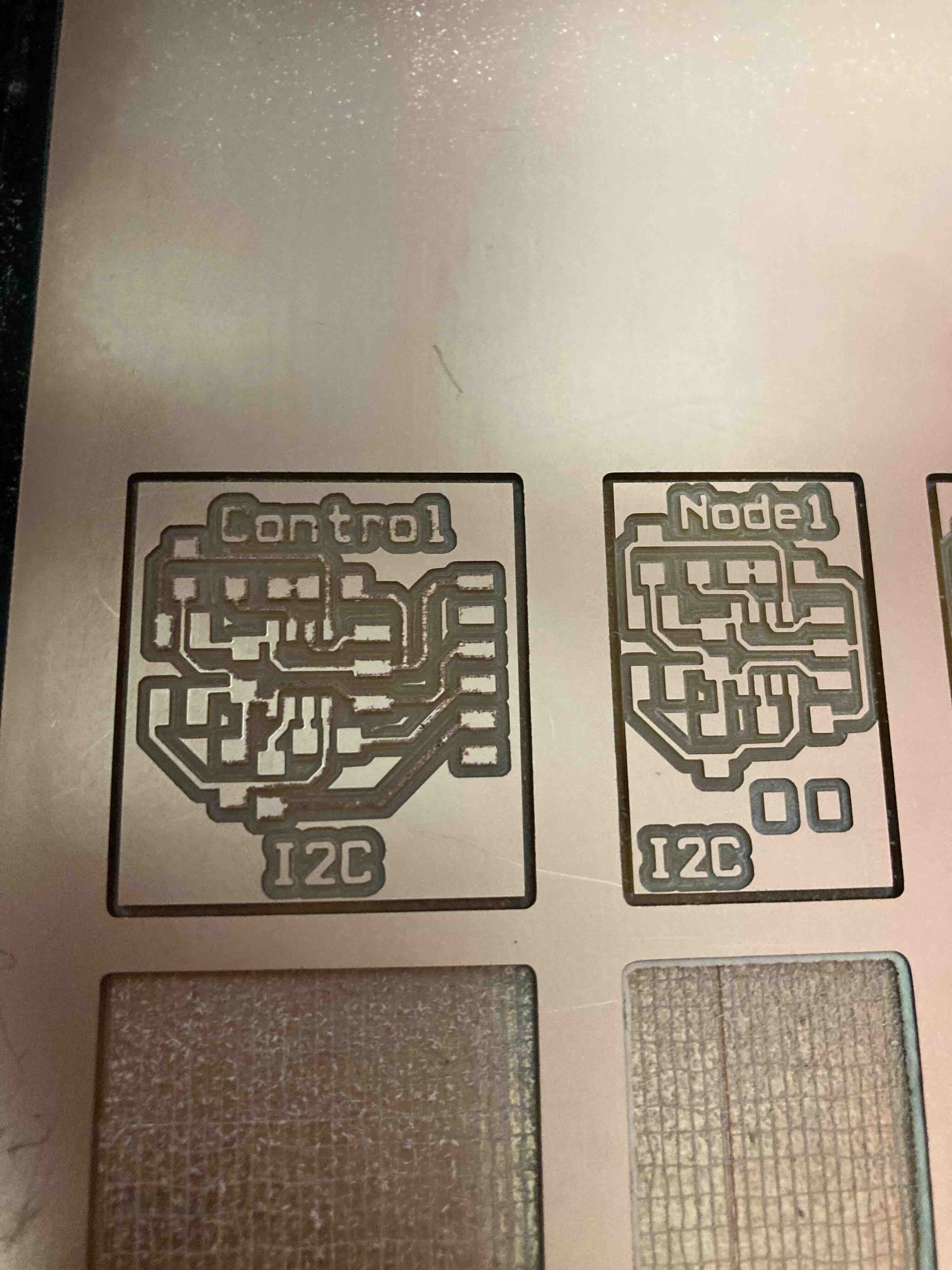
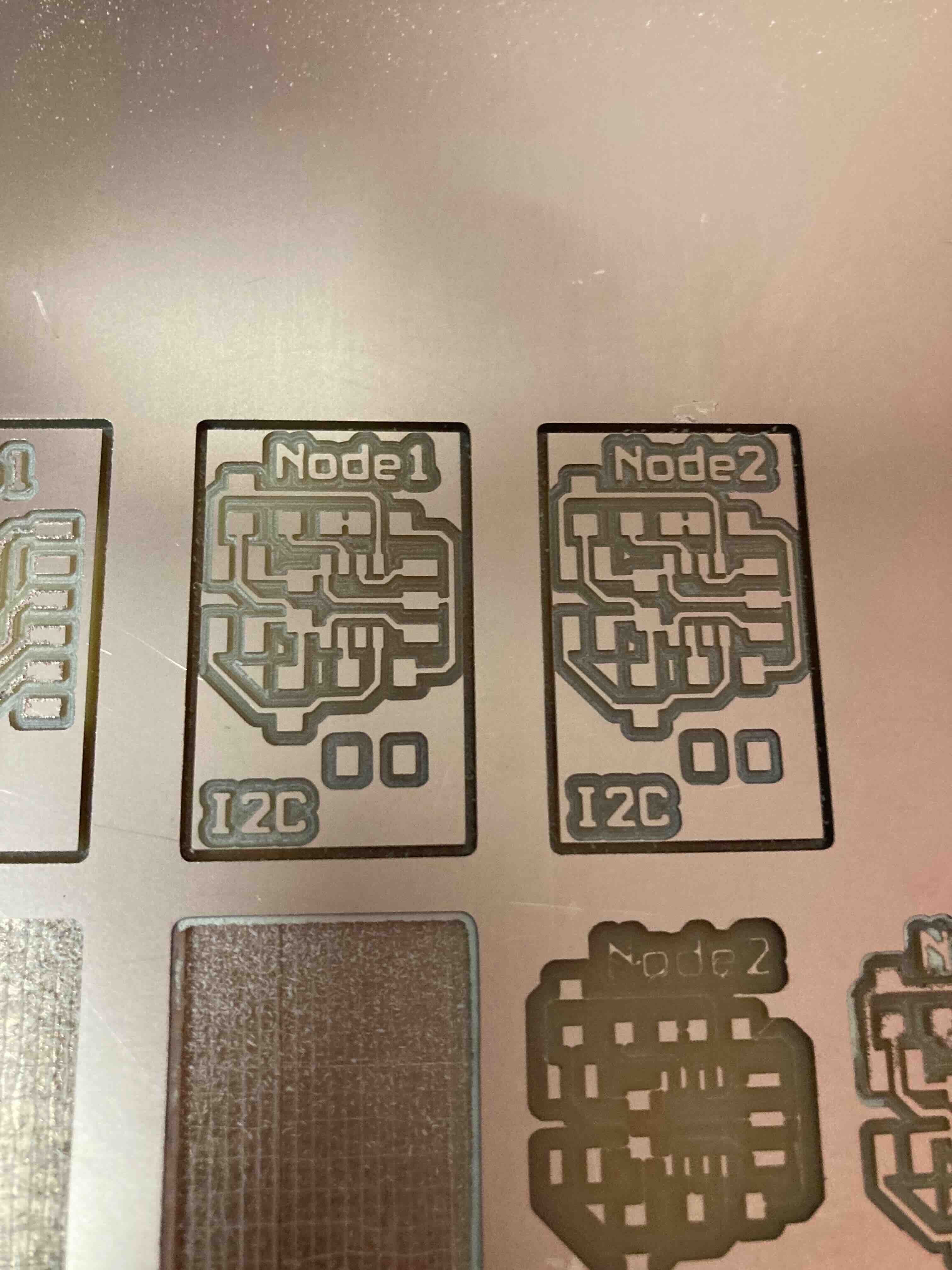
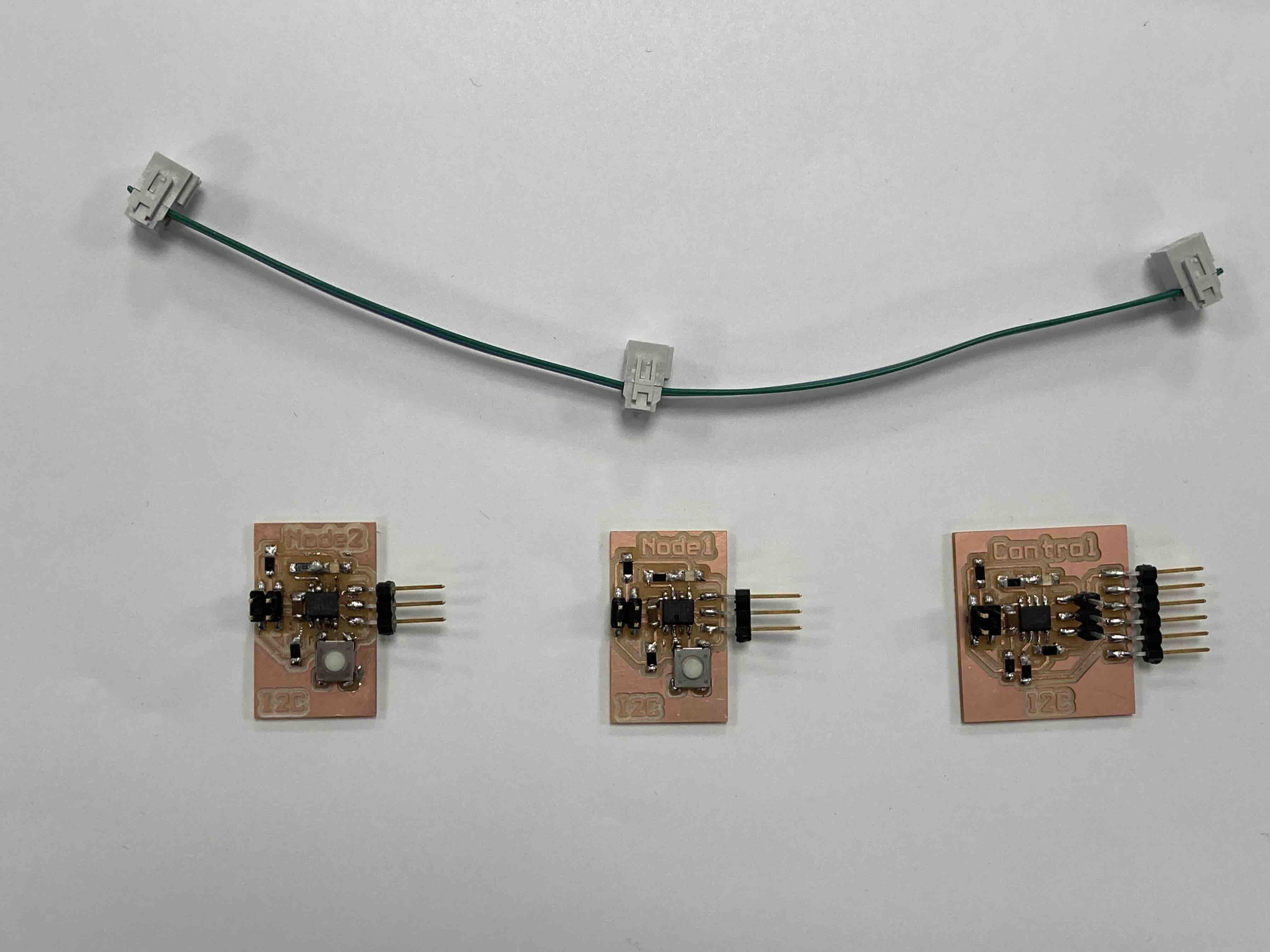
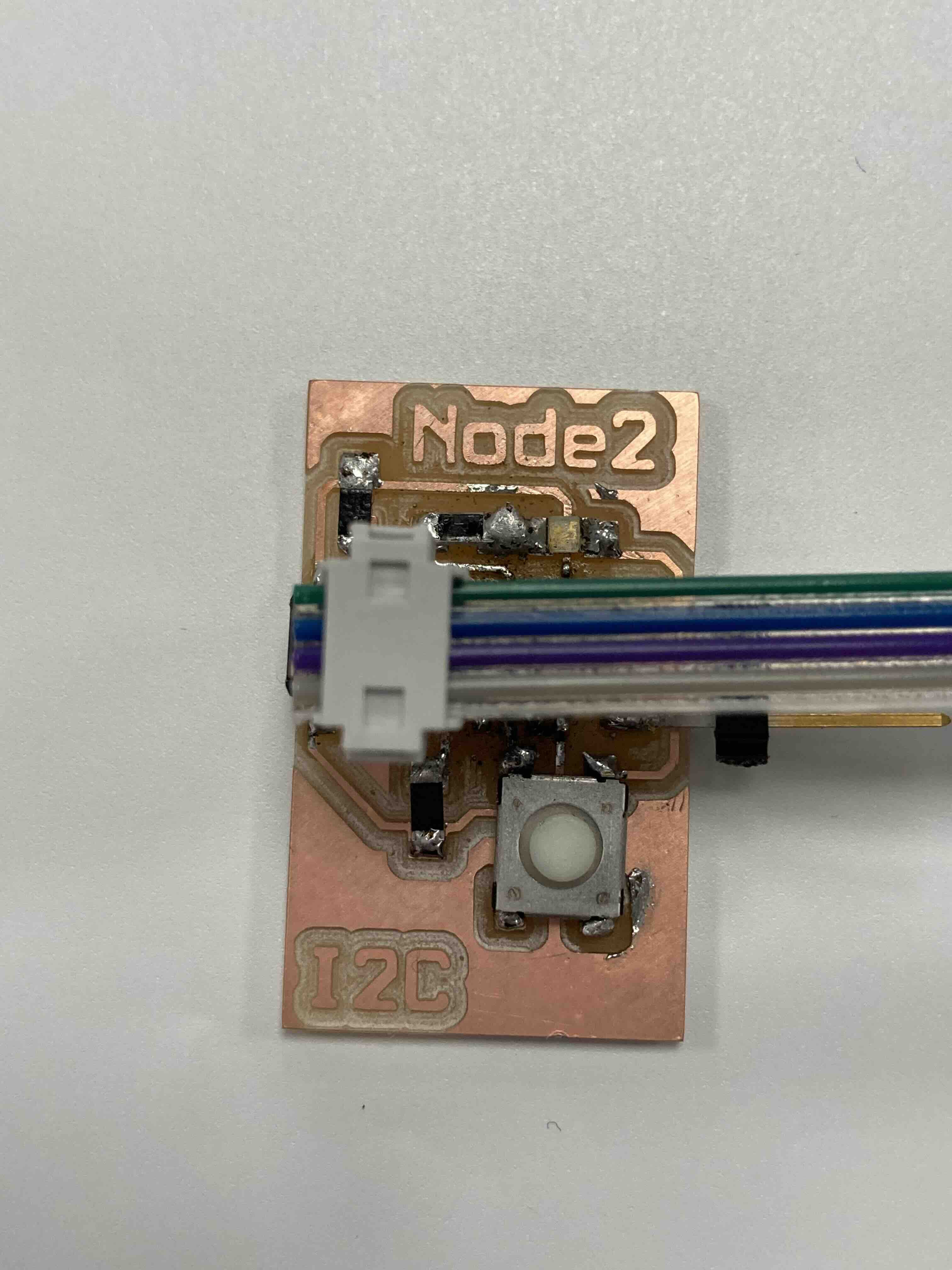
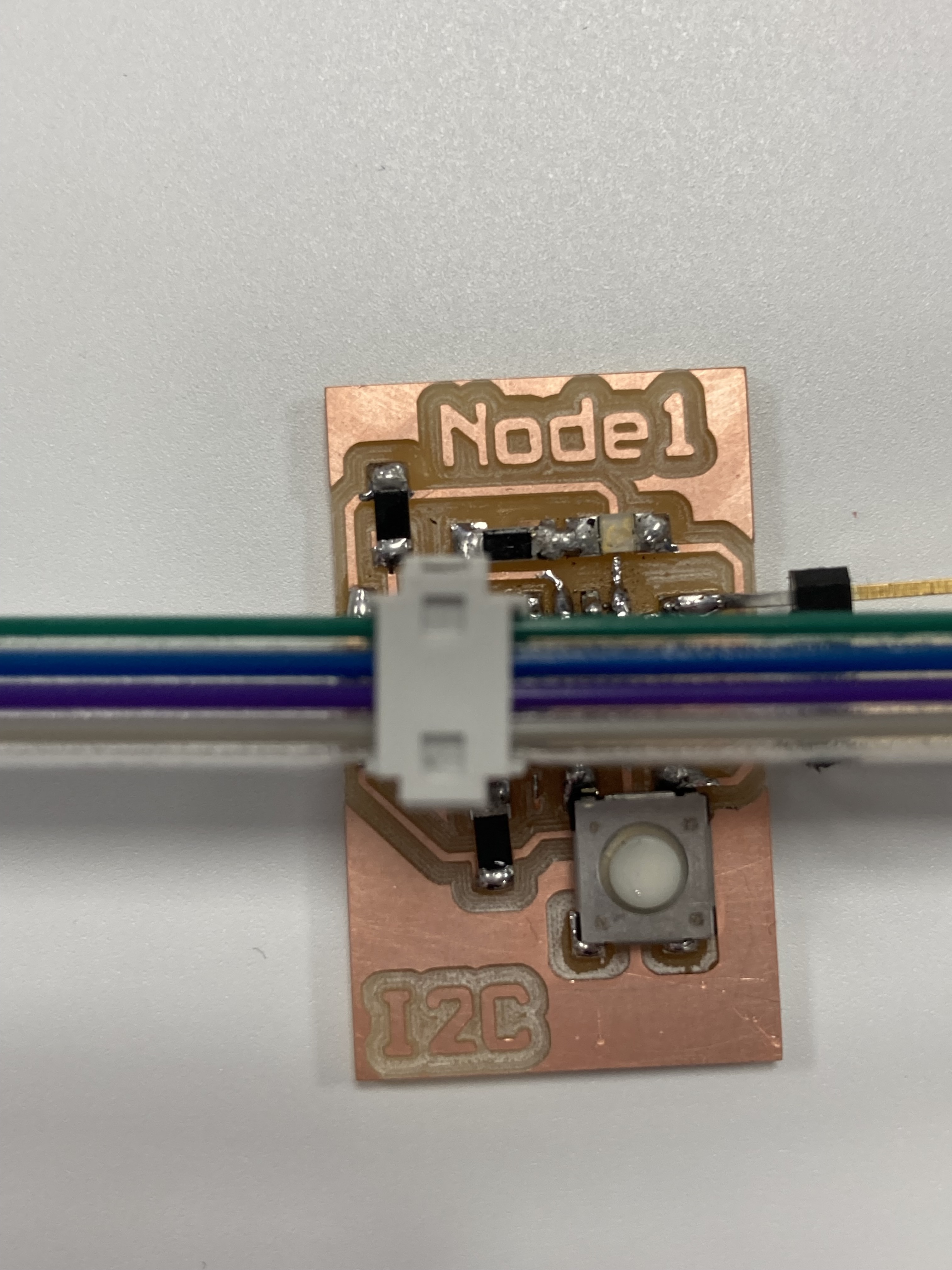
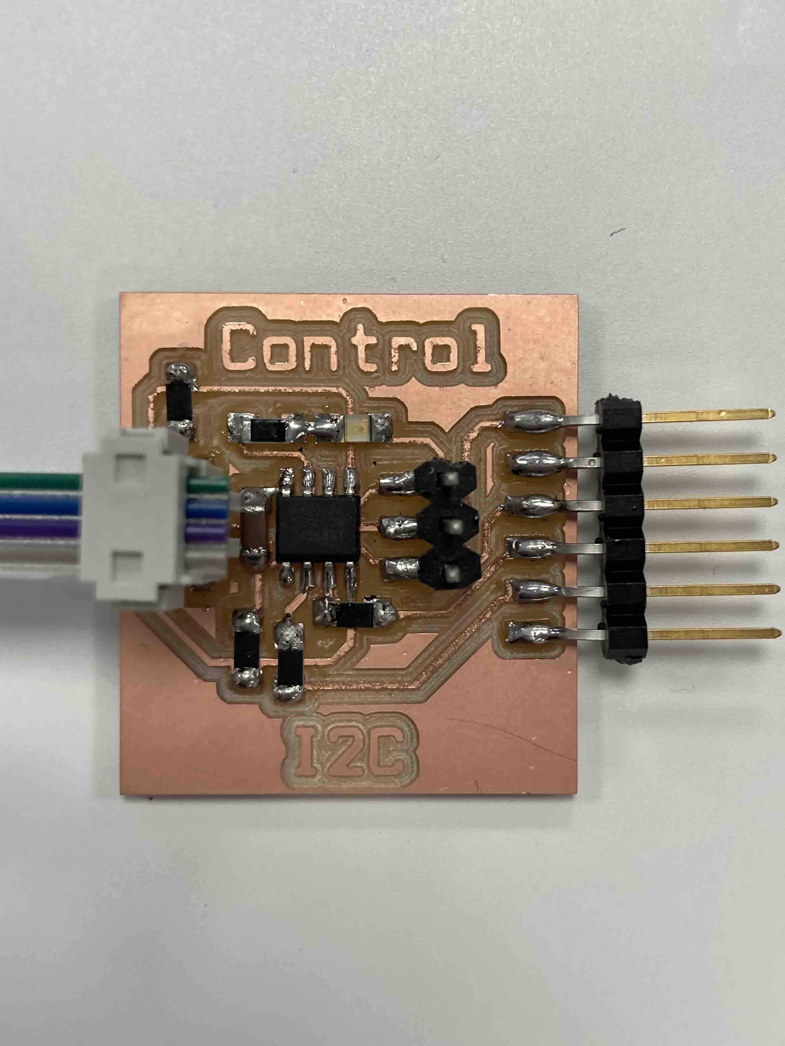
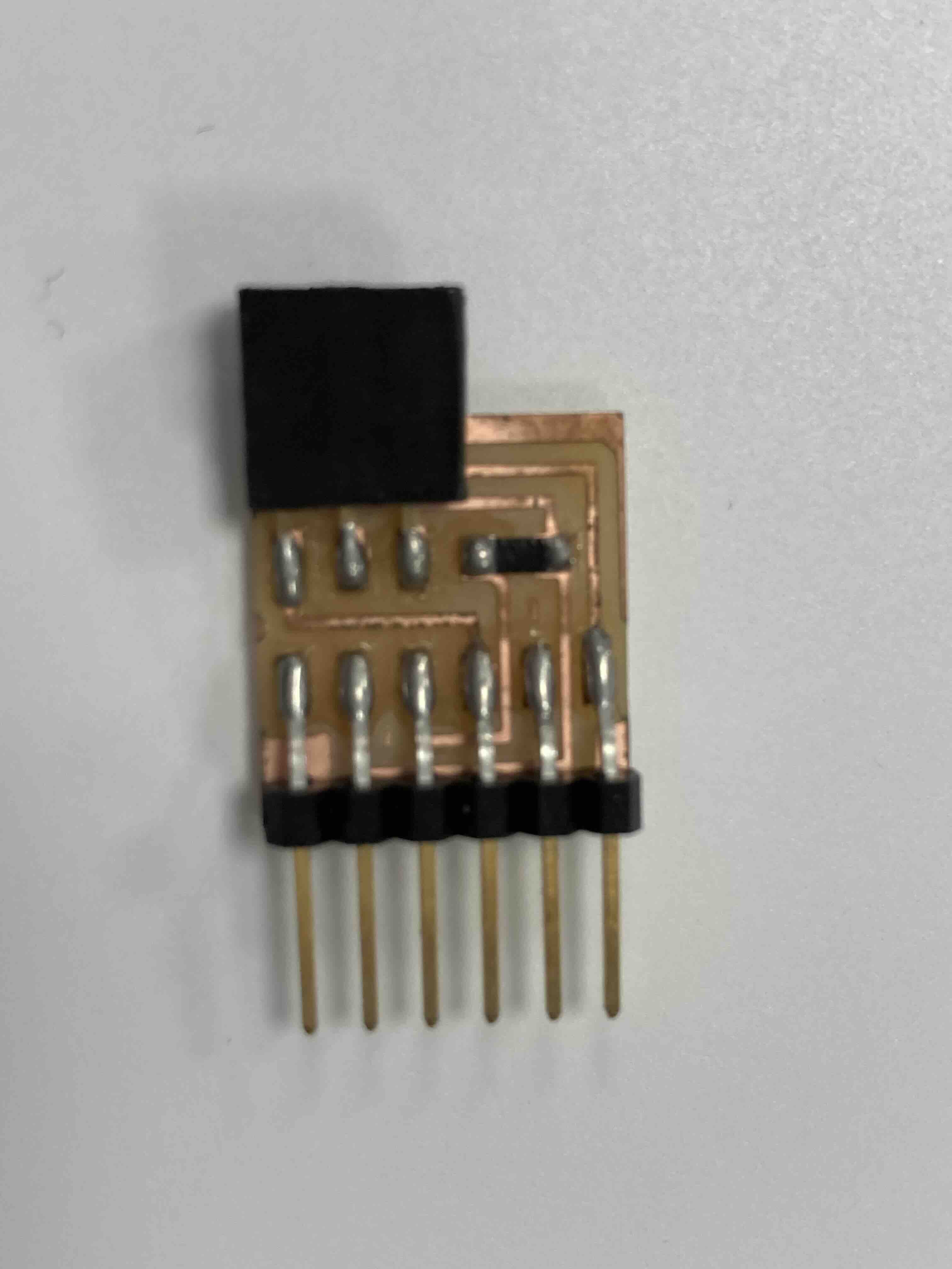
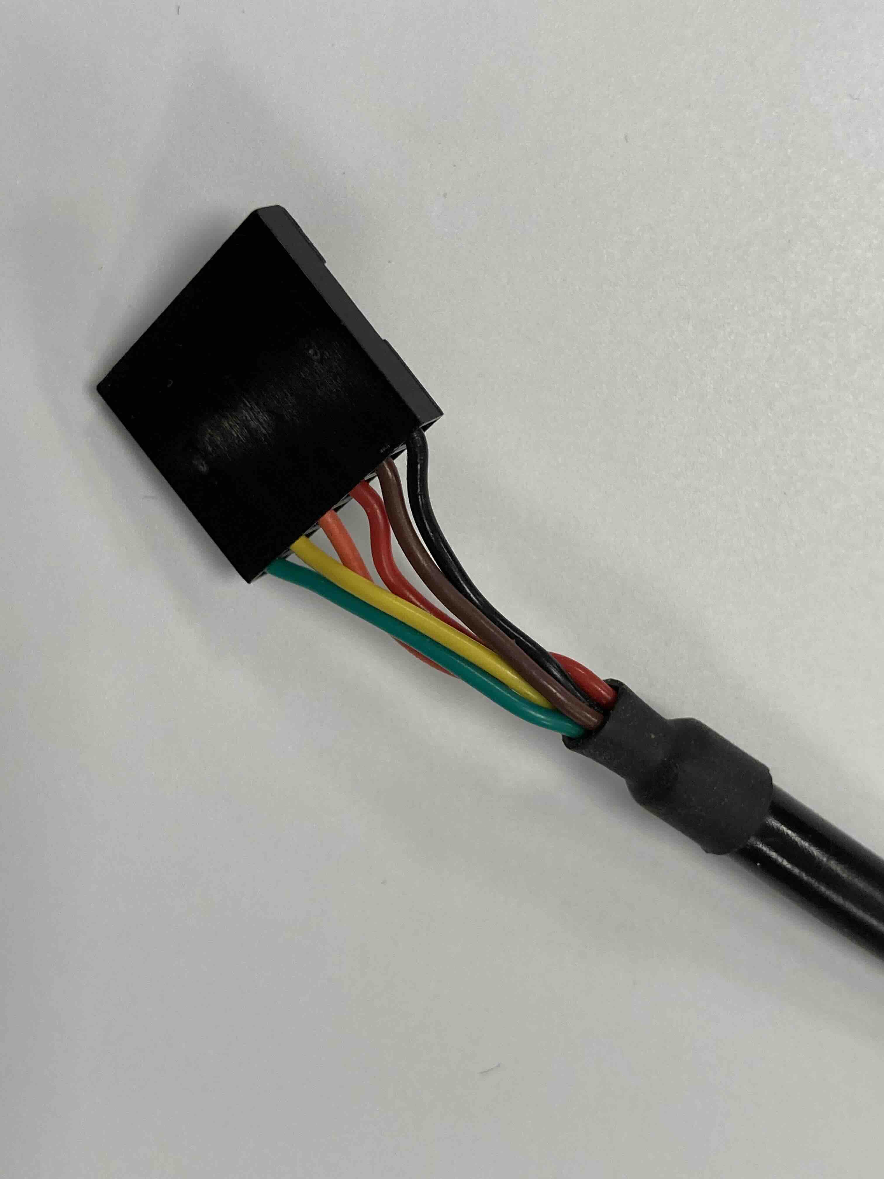
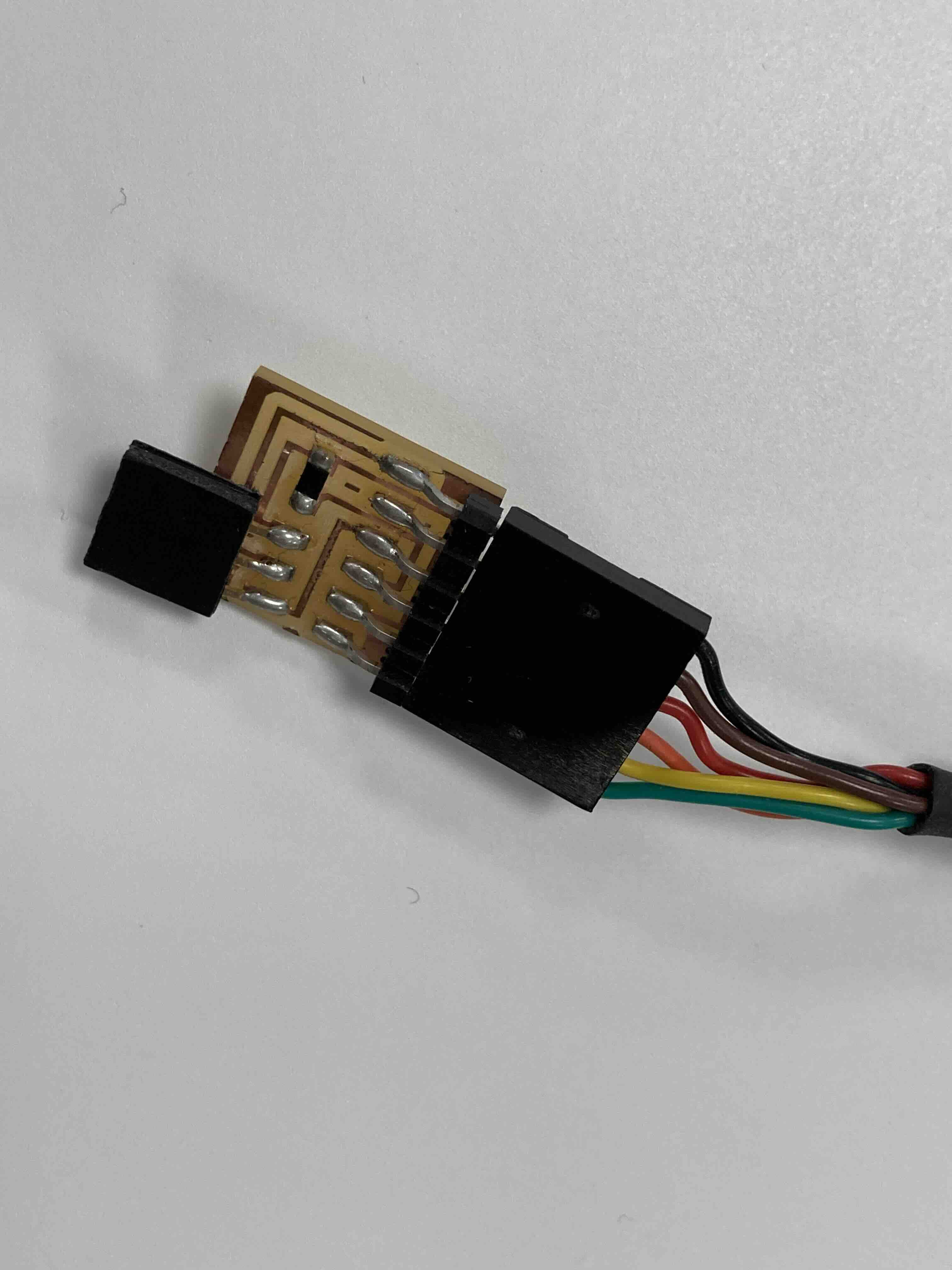
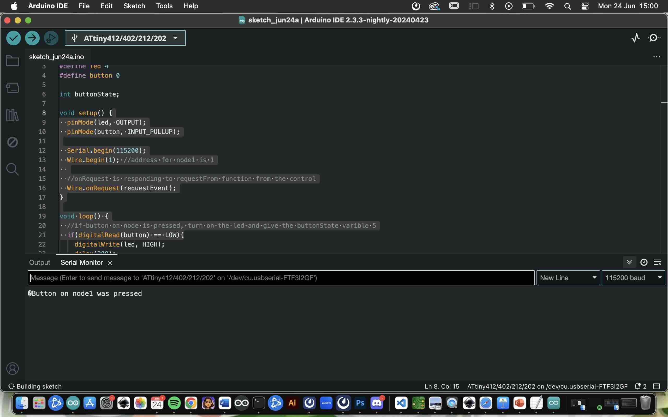
Design, build, and connect wired or wireless node(s) with network or bus addresses and local input &/or output device(s). I learned to use I2C that uses 4 wires VCC, GND, SDA and SCL. In an I"C (Inter-Intergrated Circute), SDA (Serial-Data) is usedfor the bidirectional data transfer, while SCL (Seriial Clock) is used to syncronize the data transfer between devices. With 7-bit addressing you can have up to 127 nodes in the network. Problems I encounted: node 2 board wasnt soldered properly and I had to use jumper wires to get it to work. (pic down below)