Individual Assignment
Design, build, and connect wired or wireless node(s) with network or bus addresses.
Group Assignment
Send a message between two projects.
Document your work to the group work page and reflect on your individual page what you learned.
Learning outcomes
- Demonstrate workflows used in network design.
- Implement and interpret networking protocols and/or communication protocols.
Design, build, and connect wired or wireless node(s) with network or bus addresses.
For my final project I am making an arcade machine, which requires a joystick and buttons. I have not fully decided on how I want to implement the inputs for the arcade but I2C communication from the buttons and joystick to the main board seems like a good idea. In my final the main board is a Teensy 4.0 and the inputs (for now) are connected to an ATtiny412.
For this week to test the I2C communication protocol I will be making a control (main/master) board with an led, and (slave) nodes with an led and a button. I will use my 412 led/button board I made in Electronics Production week as a base for my nodes(slaves).
412 board with an led and a buttong from Electronics Production week
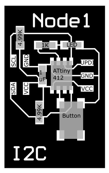
This board needs a few things to be able to communicate using I2C. Looking at Adrians Hello I2C with ATtiny 412 project I noticed he used 4.99K resistors for the SCL and SDA lines so I copied that. I also added the 4xpins for the VCC, GND, SCL, SDA lines for I2C communication.
I copied my board design from my SVGPCB project and brought into Inkscape to finalize the design.
I2C nodes (slaves)
412 I2C node board design
412 I2C Node board soldered
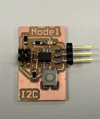
I ran into minor issues when soldering my node boards. First issue was the button, the footprints were not rotate correctly, which I didn´t notice until I was about to solder the button to the board. So, I rotated the footprint for the button in Inkscape and milled again. I desoldered the components from the old board and soldered again to the new design with the correct button footprint rotation. Another issue I didn´t notice until I had fully soldered both node boards was bridging between the SCL and UPDI pins. I had to desolder the ATtiny412 from both boards and cut the bridges. Then after soldering the ATtiny412 back on the boards everything worked as expected.
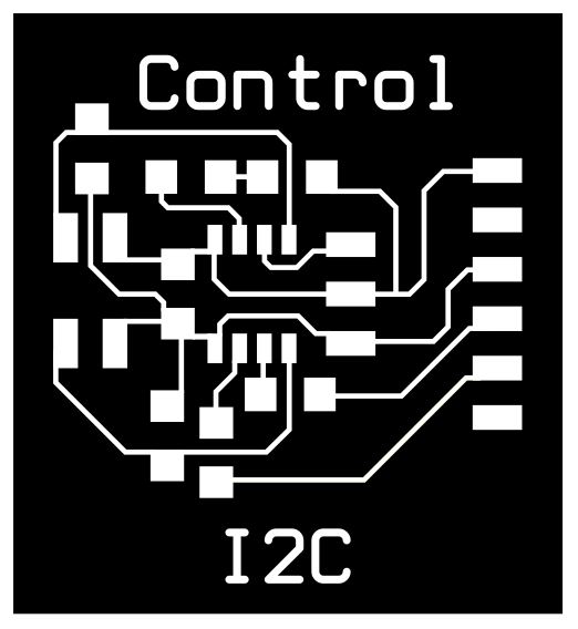
I2C Control (master)
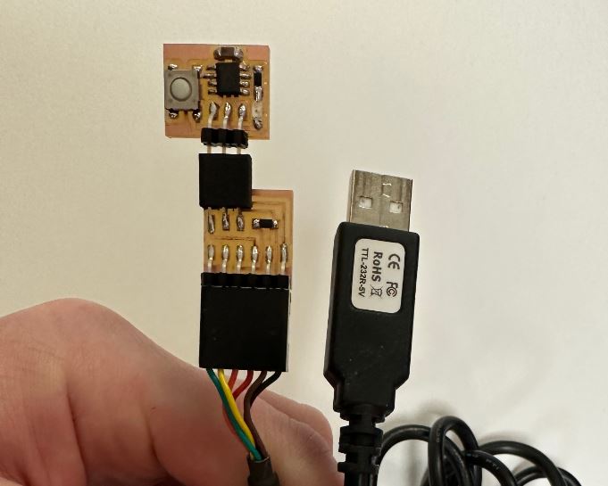
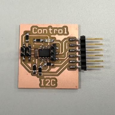
For the control board I copied the node design, removed the button and added FTDI pins for Serial communication. I also added jumpers, 0 Ω resistors, from the TX and RX pins to the FTDI pins.
412 I2C Control board design
412 I2C Control board soldered
Download Inkscape design files for Control and Node
Milling and soldering the Control board went without issues.
To finish the first spiral for this project, getting the Control board to light up the leds on the Node boards I used the code from Adrians I2C project. Hello I2C with ATtiny 412 project.
I uploaded the code to the ATtiny412s using Arduino IDE, using the megaTinyCore package. I had used the megaTinyCore package before and uploaded without an issue but for some reason I got an error, "A programmer is required to upload". I tried all the programmers but always got the same error message. After some googling I tried a tip, set the programmer to SerialUPDI, go into Sketch - Upload using programmer, which finally uploaded the code. I used the same code for the nodes, except the address for each node. Then I used the master code from Adrian unedited.
Download Master code (Adrians code)
Download Node code (Adrians code)
Second spiral
Getting the button on the Nodes to communicate with the Control board
For this spiral I wanted to use the button on the Node boards to communicate with the Control board. I found an example online where a slave device communicates with a master board. I used the example code to learn from and made my own code using what I needed.
I was able to make everything work, the Control boards blinks when a button is pressed on either one of the Node boards. Now I may be able to use this method to control the buttons and joystick in my final project, the arcade machine.
Third spiral
Getting the button on the Nodes to communicate with the Teensy and LED matrix for the final project
For this spiral I wanted to use the button on the Node boards to communicate with the Teensy and LED matrix for the final project, the arcade machine. I used the same code as in the second spiral for the Node board with the button but the code on the master was the same I2C code as in spiral 2 mixed with an example code from the SmartMatrix library, the disco effect is triggered when the button is pressed.
I2C with the 412Node board, Teensy 4.0 and a 32x32 LED Matrix
I got I2C communication to work with the Teensy and with the 412 Node board. There are some weird artifacts that follow the text but I´m just happy I got I2C to work. This gets me that much closer to controlling the LED Matrix for my final project.