Final Project Ideas
Sign language Thing hand
My original idea was to create the Thing from the Addams family, a hand that could walk on its fingers. I am not sure how I can accomplish this so I thought of creating a sign language hand. The sign language hand would be networked and connected to a website. Users could type in letters or words on the website and the hand would sign out the letters or words. The hand would be 3d printed and placed on a laser cut platform. The electrical components would be housed in the laser cut platform and would include a milled circuit board loaded with motors and networking components.
This would be an exciting project but I am not sure how I would accomplish the fine movement on the hand for the sign language let alone how I would get the hand to be able to walk.
Mini Arcade device
I have wanted to create an arcade machine for quite some time now using a rasperry pi and a monitor in a laser cut or CNC milled housing. As a Fab Academy project I would like to make a mini arcade machine by creating a 32x32 or 64x64 LED matrix screen. The screen would be housed in a laser cut enclosure with 3d printed housing for the buttons and electronics.
My biggest concern is the game programming aspect and making sure the microcontrollers have enough memory. This can probably be solved by using SD-card memory or other addition memory components but right now I am not sure how to accomplish this.
Vermicompost monitoring system
I have been mulling over the idea of creating a vermicompost monitoring system. A successful vermicomposting system requires certain conditions such as optimal humidity, temperature and more. My idea is to use sensors, such as humidity, temperature, gas, ph and possibly more sensors to monitor a vermicomposting system. The data gathered from these sensors would be sent via WiFi and displayed on a website. The project would use a laser cut or CNC milled box to house the worms and compost, 3d printed housing for the electricals which would include a milled circuit board loaded with sensors and networking capabilities.
Although this is a viable project I would like to keep my options open and consider other projects.
Final Project
Originally I had planned to make the Mini Arcade Device project. I had all the components, the LED Matrix dispaly, buttons and joystick and during the Fab Academy I have been trying to do something in my weekly projects that I could use in the arcade. During the Output Devices week I noticed a glitch in the LED Matrix display. I tried everything I could think of to fix the issue, tried different controllers, different libraries, resoldering, asking on forums and even got in contact with the creator of the LED Matrix SmartShield that I was using but I was unable to fix the display. By the time I realized the issue it was getting too late to order a new one so I moved on and decided to go for another project.
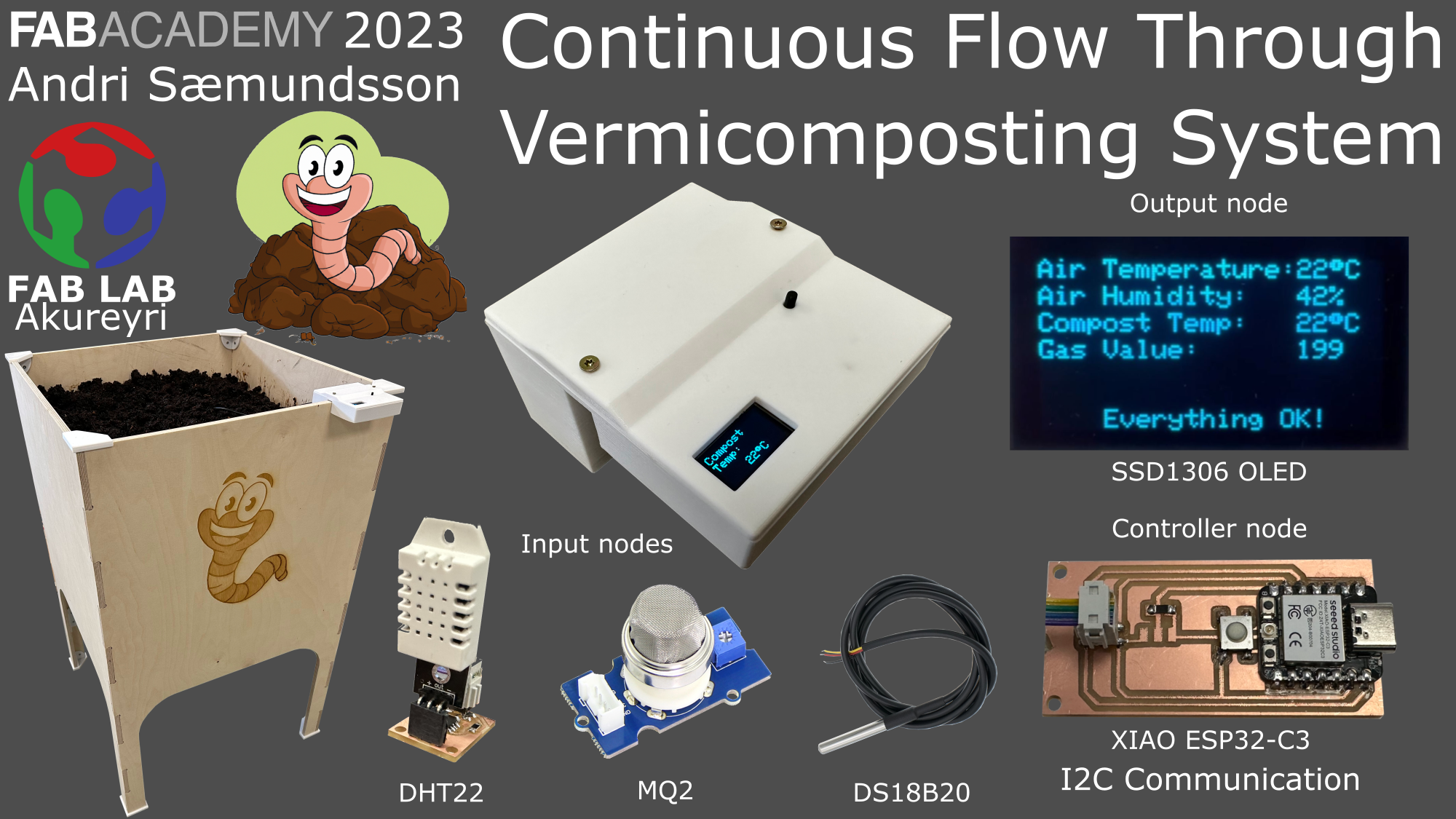
Continuous Flow Through Vermicomposting System
Research
What will it do?
CFT system
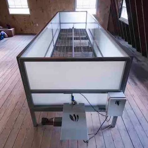
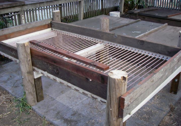
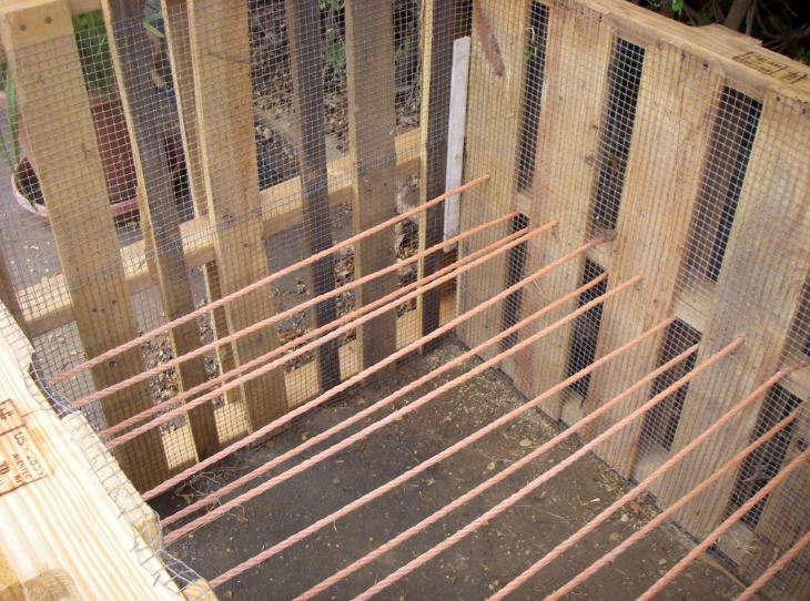
A CFT (Continuous-Flow-Through) vermicomposting system is a method of vermicomposting where composting worms are fed organic matter from the top and worm castings are eventually harvested from the bottom. The bottom of a CFT system has bars or a mesh to let the worm castings fall through. The top of the system has a lid to keep the worms in and to keep the system dark. The system is usually made from wood or plastic. Some systems have automatic harvesting where a motor pulls a bar across the bottom of the system to push the worm castings out. Other systems rely on manually harvesting with a rake. For the first spiral I will be making a system that relies on manually harvesting with a rake. In later spirals I will add automatic harvesting with a motor.
The technology
The CFT system will have sensors to monitor the conditions of the compost. There will be a Humidity and Temperature sensor to monitor the air outside the system. There will also be a waterproof temperature sensor within the compost to monitor the temperature of the actual compost. Other sensors such as gas sensors and compost humidity sensors may be added to the system in later spirals. The data will be saved to a SD card and/or sent to a server. The data will be visualized on an OLED display and/or on a website.
So, I will be making a CFT (Continuous-Flow-Through) vermicomposting system with sensors to monitor the conditions of the system. The CFT system itself will be about 1 sq/m in surface area. The sensors will be connected to a XIAO Esp32-c3.
Who's done what beforehand?
Commercial CFT
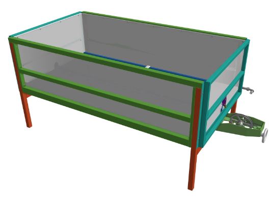
There are commercial CFT systems readily available to buy. The Urban Worm Company sells an assembled version of a modular CFT system from $6995 or you can buy the design plans for $1555 and build it yourself.
CFT Assembled
CFT Design Plans
DIY CFT
There are several designs for a DIY CFT system. Some designs are open and free while other are paid for.
Eco Farming Daily has designs for CFTs and tips and tricks for vermicomposting.
DIY CFT
DIY CFT
Fab Academy projects
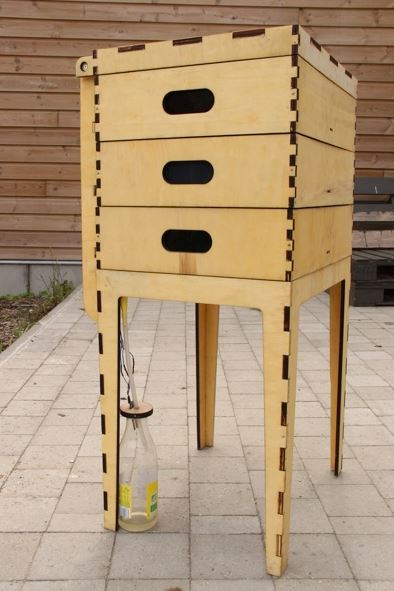
Looking through previous student projects I did not find any large-scale CFT systems like I plan on making. Benjamin Lemay however made a stacking vermicomposting system that I can use as inspiration. Lucia Jonkhoff also made a project that monitors a vermicomposting system using sensors.
Stacking system (Benjamin Lemay)
Vermicompost sensors (Lucia Jonkoff)
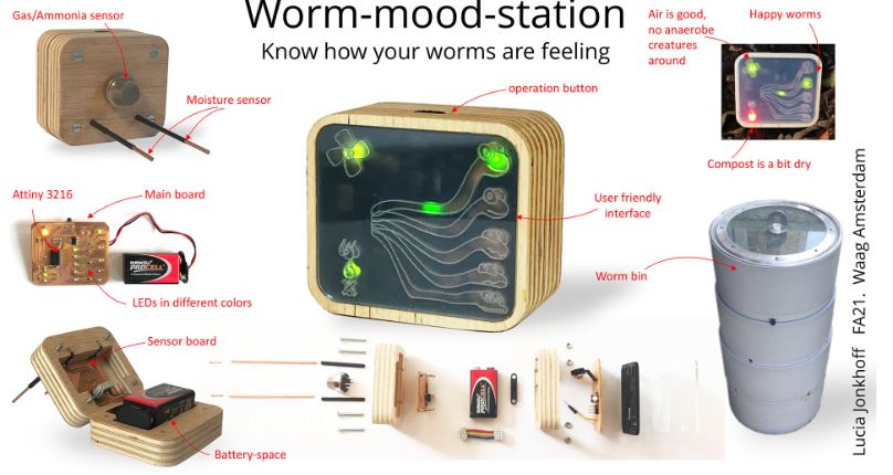
I will most likely be referencing Lucias project since her project used the same type of sensors I intend on using.
Plan
What will you design?
CFT system
I will design the CFT system. For reference and inspiration I will draw from both commercial CFT systems and DIY designs. For the first spiral I will make a manually opererated harvesting system but eventually I would like to incorporate automatic machined harvesting.
Technology
I will design the PCB board that will have the microcontroller and all the sensors. The first spiral will be getting everything working properly, then on later spirals I want to make a modular system where sensors can be added or removed easily. I will also design and 3d print a mounting case for the electronics.
Hardware
What materials and components will be used?
CFT system
The CFT system will be made from wood. I will be using 2x4s and plywood. I will also be using screws and nails to hold the system together. For the bottom of the system I will be using a mesh or bars to let the worm castings fall through.
Technology
I will be using a XIAO Esp32-c3 microcontroller, DHT22 Temperature/Humidity sensor, DS18B20 waterproof sensor, MQ2 gas sensor and a ssd1306 OLED display. A PCB will be designed and milled where all these components will be soldered.
Where will come from?
CFT system
Byko and Húsasmiðjan are hardware stores in Iceland where I can purchase all the wood, screws and stuff needed for the CFT system.
Technology
I already have all the electrical components. Here you can see links to all components.
- XIAO Esp32-c3
- DHT22 Temperature/Humidity sensor
- DS18B20 Waterproof temperature sensor
- MQ2 Gas sensor
- SSD1306 OLED display
How much will they cost?
CFT system
The price for wood and plywood has increased a lot recently in Iceland. A 12 mm plywood 150 cm x 300 cm is priced from $65 and up. The lab has some plywood that I can use for my final project.
Technology
- XIAO Esp32-c3 $4.99
- DHT22 Temperature/Humidity sensor $7
- DS18B20 Waterproof temperature sensor $3
- MQ2 Gas sensor $7.60
- SSD1306 OLED display $3
- Total: $25.59
What parts and systems will be made?
CFT system
The CFT system will be made from plywood, 2x4s and either a mesh or bars for the bottom.
Technology
The PCB will be designed and all components will be connected on the PCB. If I have time I will make a humidity sensor from scratch.
Housing for the electronics will be designed and 3d printed.
Designing the CFT System
Sketches
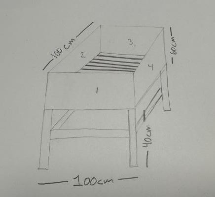
To figure out exactly how I am going to make the CFT box that holds the worms and compost I made a few sketches to visualize everything.
CFT - Original sketch
CFT - Brainstorming sketches
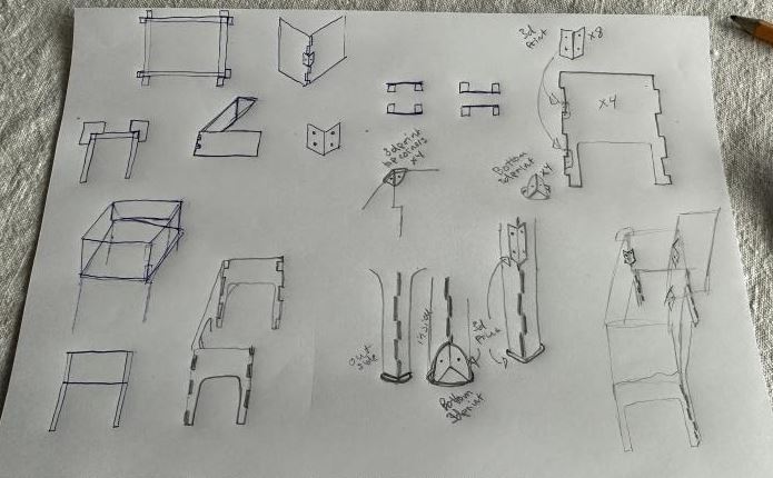
CFT - Sketches of things to make
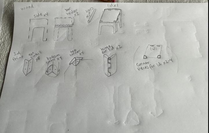
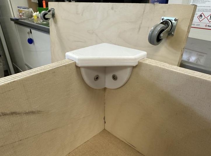
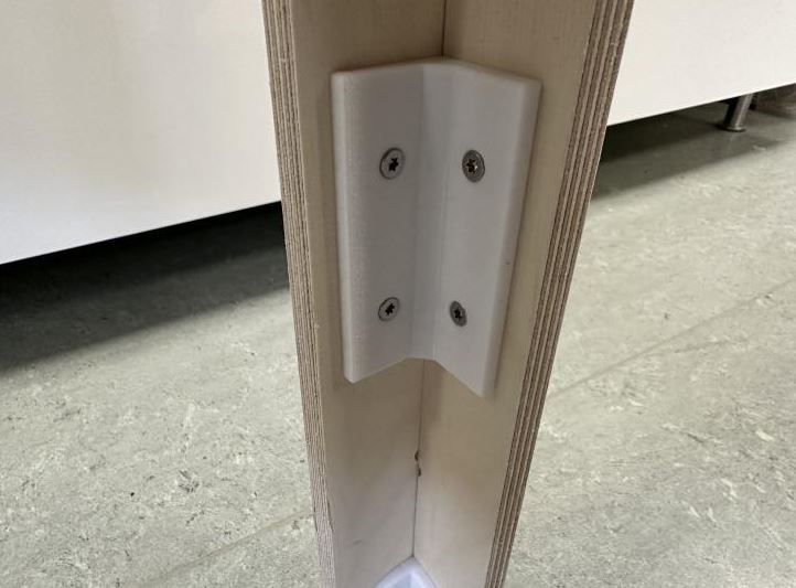
During the brainstorming session I decided to make the entire CFT box with the CNC shopbot. I liked how Benjamin Lemay made the legs for his system so instead of inventing the wheel again I borrowed his idea. I also intend to design and 3d print 90° degree brackets to support the finger joints and corners. The structure needs to be well supported and strong because there will be quite a lot of weight in the CFT system when it is full with compost.
Making the CFT System
Fusion 360
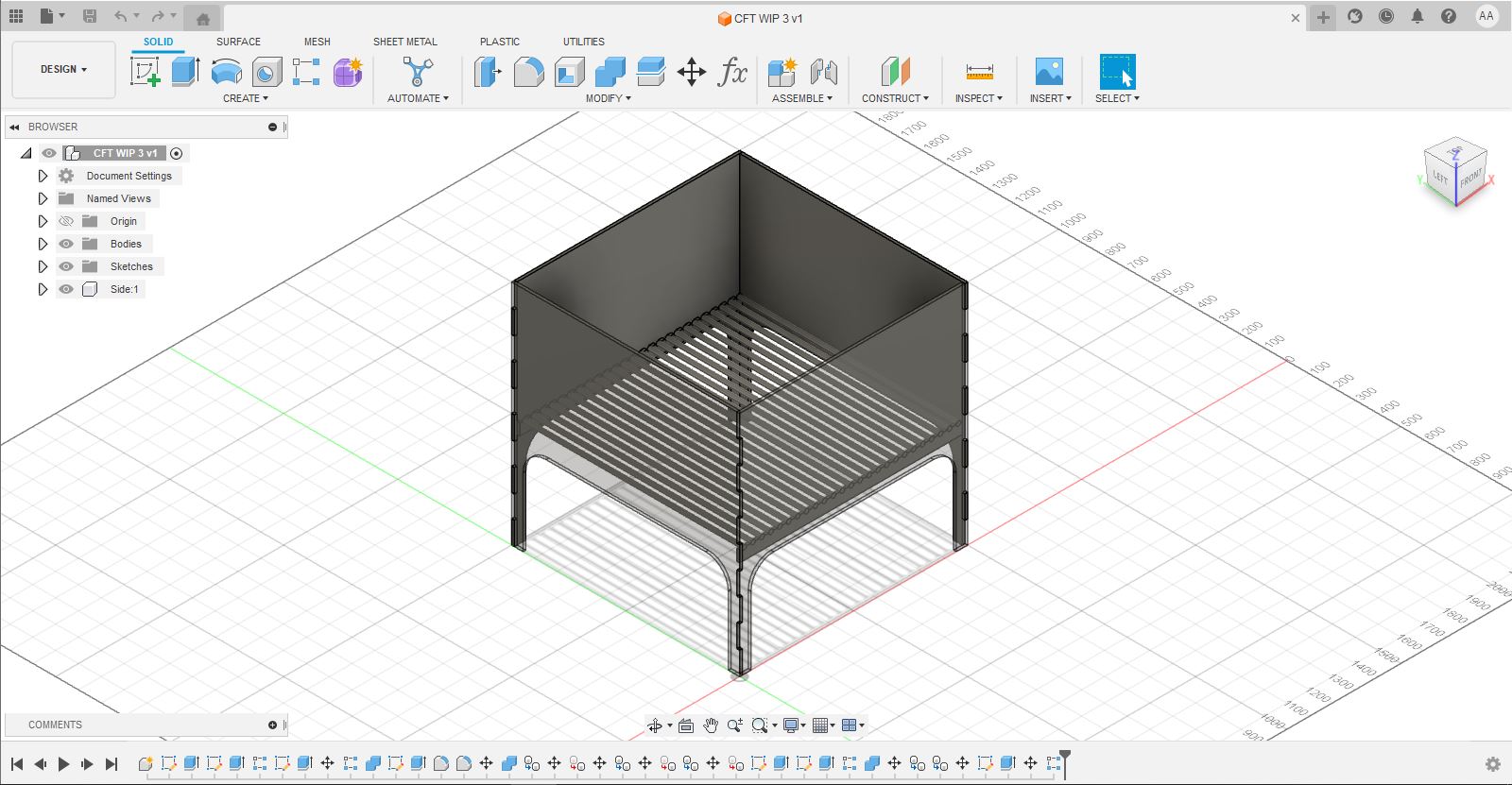
Once I had my plan I jumped into Fusion and started modeling. I want to use parameters where I can so I can make different size systems with different material thickness.
CFT - Fusion 360 Model
CFT - Fusion 360 Parameters
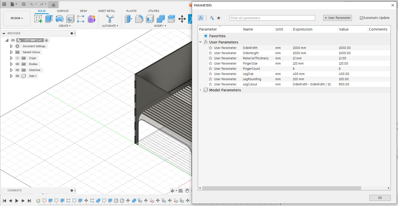
Using the Fusion parametric model I should be able to change any dimension and the model should update correctly.
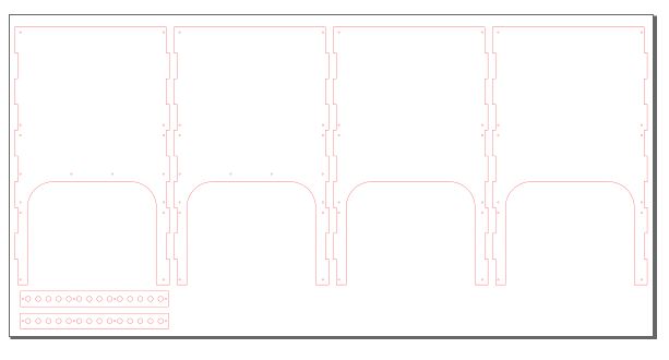
CFT - Inkscape
After spending two days making the Fusion 360 model I decided to make the model again, but this time using Inkscape. Before jumping into Inkscape I measured the plywood sheet that I had. The plywood sheet was 1250 mm x 2500 mm x 12 mm. I wanted everything to fit on one sheet so I had to adjust the size of the model to fit. The height was the same as I had decided at 1000 mm, but to fit everything on the plywood sheet I had to make the sides 600 mm instead of 1000 mm.
In Inkscape I made more details than in the Fusion model, adding markers for where all screws should be. I was able to make the Inkscape file in less than two hours.
CFT - Inkscape
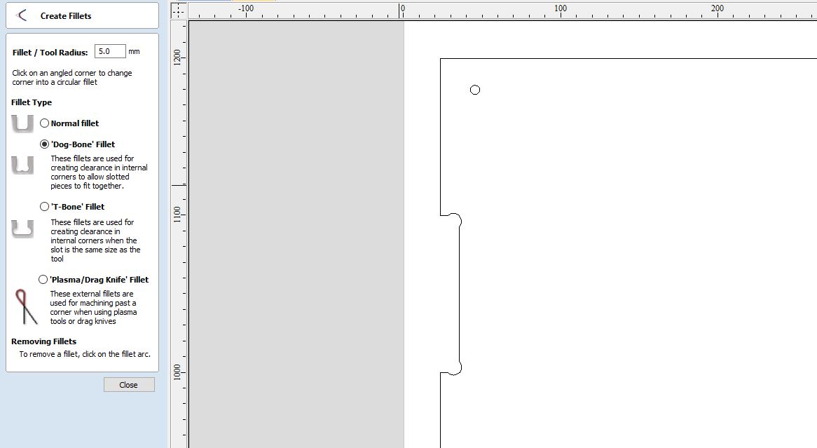
CFT - VCarve
Once I had the Inkscape file ready I jumped into VCarve to make all the toolpaths for the Shopbot.
I started by making dogbones inside the finger joints to allow slotted pieces to fit together
CFT - VCarve Dogbones
CFT - VCarve Toolpaths
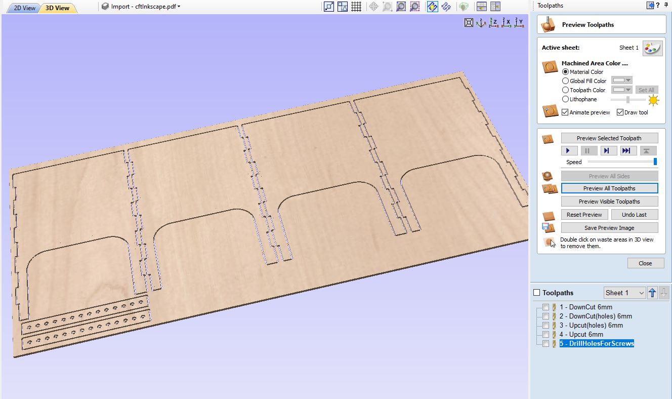
After I had all the dogbones set I moved on and made the toolpaths to mill everything. Starting with a 6mm downcut endmill I mill 3mm down into the material. Then I use a 6mm upcut endmill to go through the material leaving tabs in place to keep everything secure.
CFT - 3d printed brackets
I was not sure how well the finger joints would hold the CFT system together, especially since the system may contain a quite a bit of weight.
CFT - Corner bracket reference
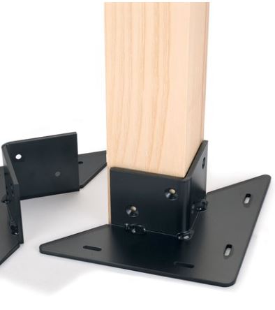
CFT - 90° degree bracket reference

After looking through different types of brackets for inspiration I started 3d modeling.
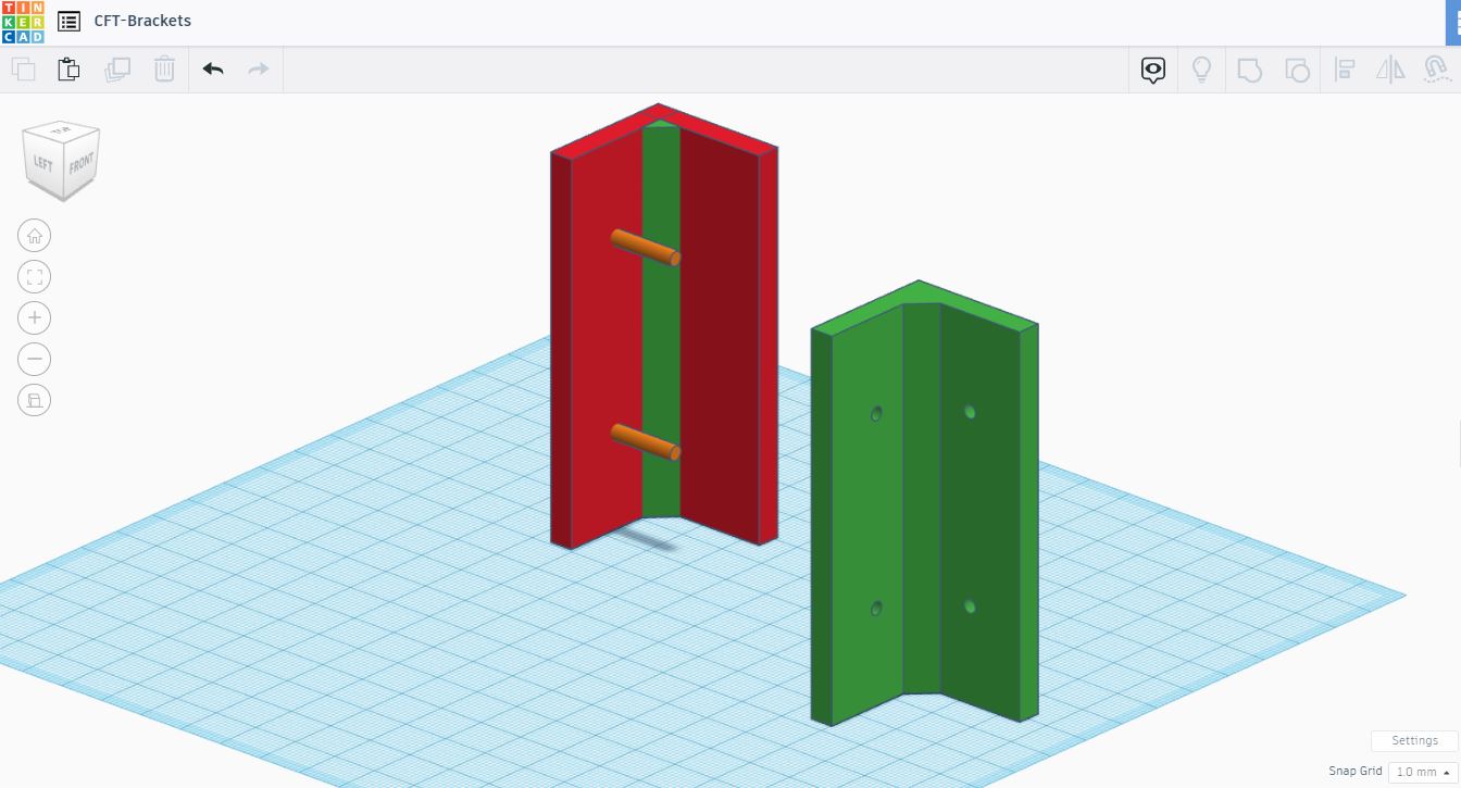
Although it is possible to get smooth beveled models in Tinkercad it does not offer a great deal of control for beveling but Tinkercad is good for quick blockout modeling. I logged into Tinkercad to blockout the models.
CFT - Tinkercad - Corner bracket blockout
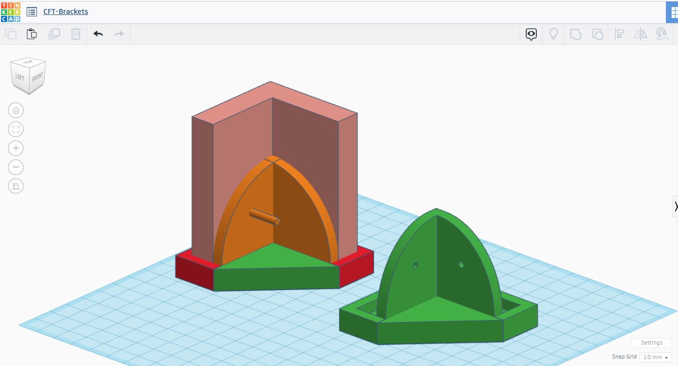
CFT - Tinkercad - 90° bracket blockout
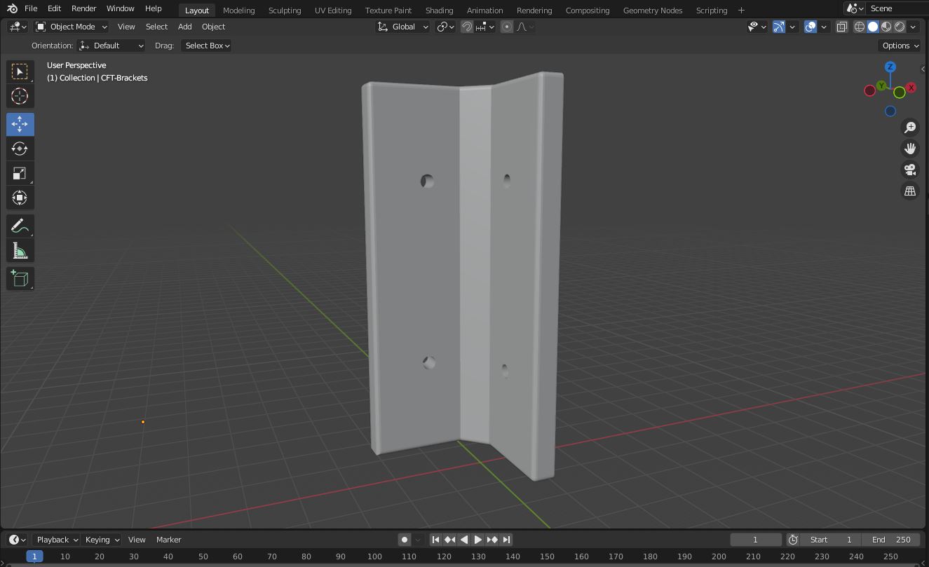
I wanted the brackets to look and feel smooth so I brought the Tinkercad models into Blender for some bevels.
CFT - Blender - Corner bracket blockout
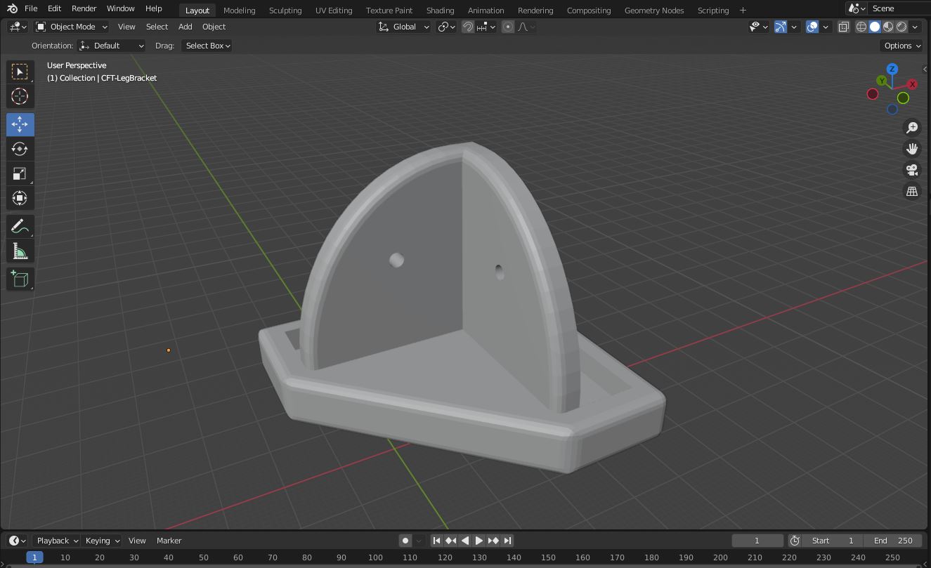
CFT - Blender - 90° bracket blockout
I imported both models into PrusaSlicer and brought the original models from Tinkercad just to compare.
CFT - Comparing models in PrusaSlicer
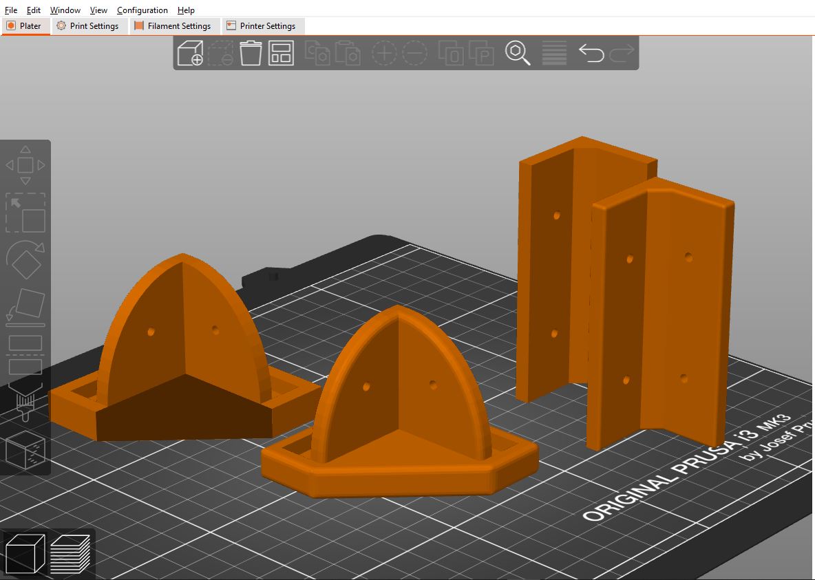
The models from Blender with the bevels definitely look better than the blockout models from Tinkercad. I´m glad I spent the time in Blender smoothing the edges.
I sliced each model individually in PrusaSlicer.
CFT - PrusaSlicer - Corner bracket blockout
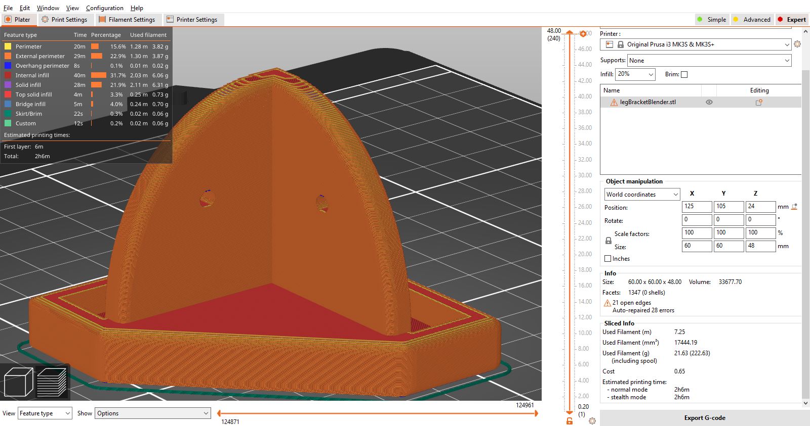
One leg bracket can be 3d printed in about 120 minutes.
CFT - PrusaSlicer - 90° bracket blockout
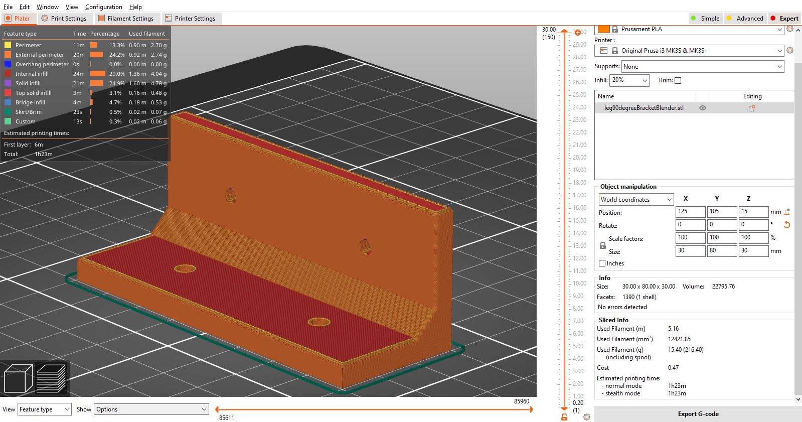
One 90° bracket can be 3d printed in about 80 minutes.
Download leg corner bracket 3d model .stl file
Download top corner bracket 3d model .stl file
Download °90 bracket 3d model .stl file
Assembling the CFT box
Before assembling everything I had to cut my aluminum pipes to size. I bought three 3m aluminum pipes and cut down in 14 pieces.
Cutting aluminum pipes
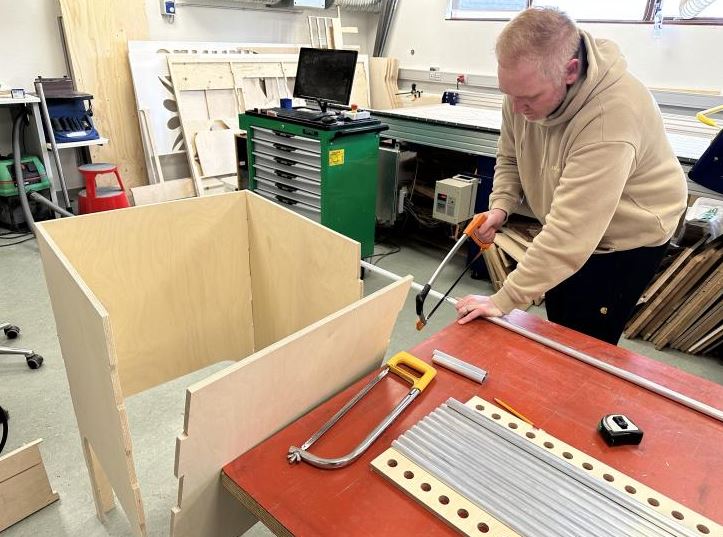
After cutting the pipes I laser rastered a worm logo on the side.
I assemebled the box, added the pipes and the 3d printed brackets for extra durability. I used wood glue in the finger joints and screws to fasten the brackets.
Top corner bracket mounted
90 degree bracket mounted
Bottom leg bracket mounted

Assembling the box
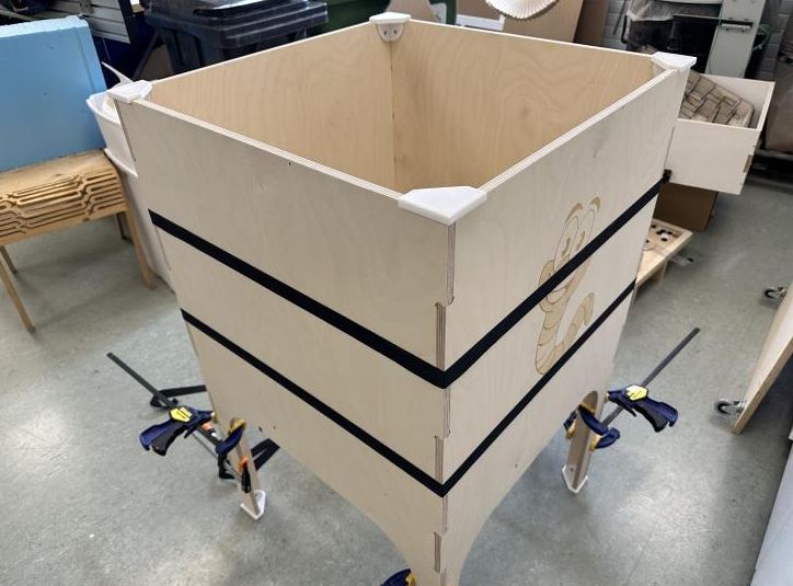
Assembling the box
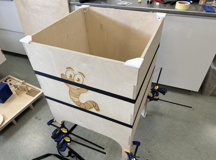
Box assembled
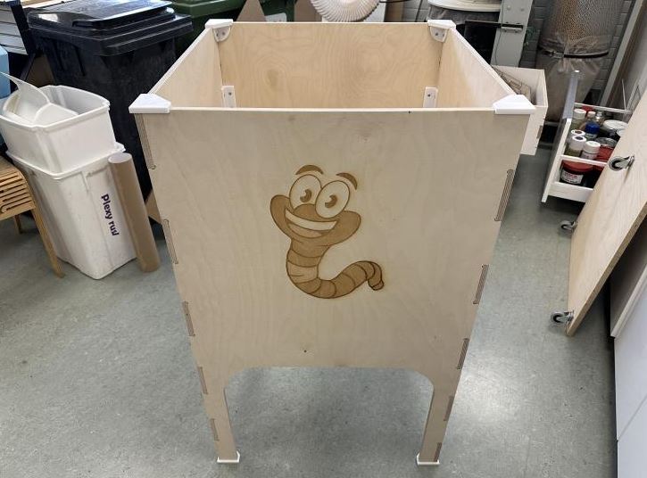
Box assembled
Now that the box is ready I can move on to the electronics.
Making the Electronics
PCB Design
Before i started the PCB design I made sure all the sensors worked using a XIAO ESP32 C3 and a breadboard. All the sensors were working fine.
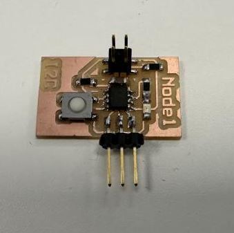
I then wanted to hook the sensors up to an ATtiny412. I want to have each sensor on its own little board and connect everything together with the XIAO using I2C. I had some 412 boards from networking week that already had I2C pins so I attempted to use those. It was a struggle using those boards because I did not have many pins to work with and they did not have FTDI pins so I could not print to a Serial monitor. So I made a test board with UPDI pins, FTDI pins, I2C pins and three extra pins for the sensor.
Node board from networking week
I am used to working in Inkscape and since I had all the footprints I needed in old Inkscape projects I copied the footprints and routed the connections using Inkscape.
Sensor Node test board in Inkscape
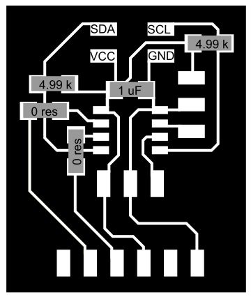
Sensor Node test board
Download Sensor node test board Inkscape file
Using the Sensor Node Test Board I was able to connect to both the DHT22 temperature/humidity sensor and the MQ2 gas sensor. After hours of trying to get the DS18b20 waterproof temperature sensor to give readings to the ATtiny412 I could not get readings. I tried the sensor with the XIAO and everything worked fine. Finally after conulting with the masters at Open Global Time they suggested the ATtiny412 was possibly not powerful on its own to read the sensor. So, I decided to put the DS18b20 temperature sensor on the Xiao board instead of putting it on its own node board.
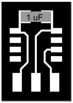
I wanted my node boards to be as minimal as possible, I wanted only an ATtiny 412, I uF capacitor, I2C pins and pins for the sensor. This meant that I needed to program the ATtiny412 before soldering it onto the board. Inpired by Quentin Bolsee´s Non-solder breakout board I made a simple board to program the ATtiny412.
The board only has the ATtiny412 footprints, UPDI pins and a 1uF capacitor.
Non-solder ATtiny412 breakout board in Inkscape
Non-solder ATtiny412 breakout board
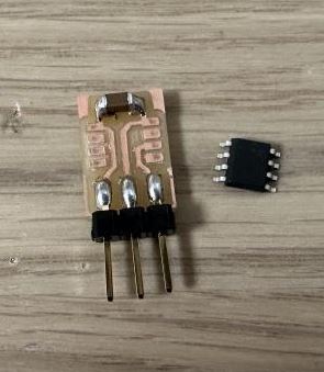
Download ATtiny non-solder breakout board .png
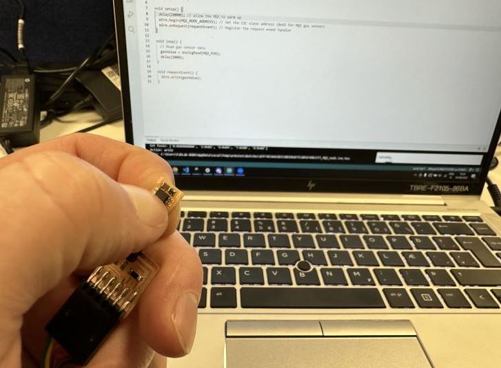
I was able to program the ATtiny412s for the DHT22 node board and the MQ2 node board using the breakout board. I just had to hold the 412 in place while it was programmed through UPDI -> FTDI -> USB.
Programming the ATtiny412 with a non-solder breakout board
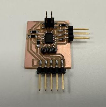
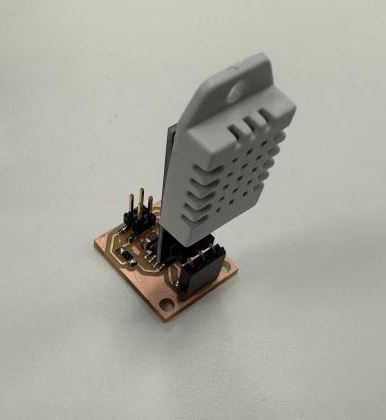
After programming the ATtiny412s I soldered them onto the node boards.
DHT22 node
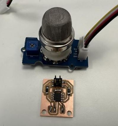
MQ2 node
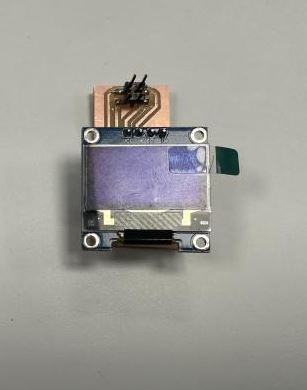
Finally I needed to add the SSD1306 OLED display. The SSD1306 uses I2C so I decided to make a simple board for the OLED.
SSD1306 OLED board design Inkscape

SSD1306 OLED board
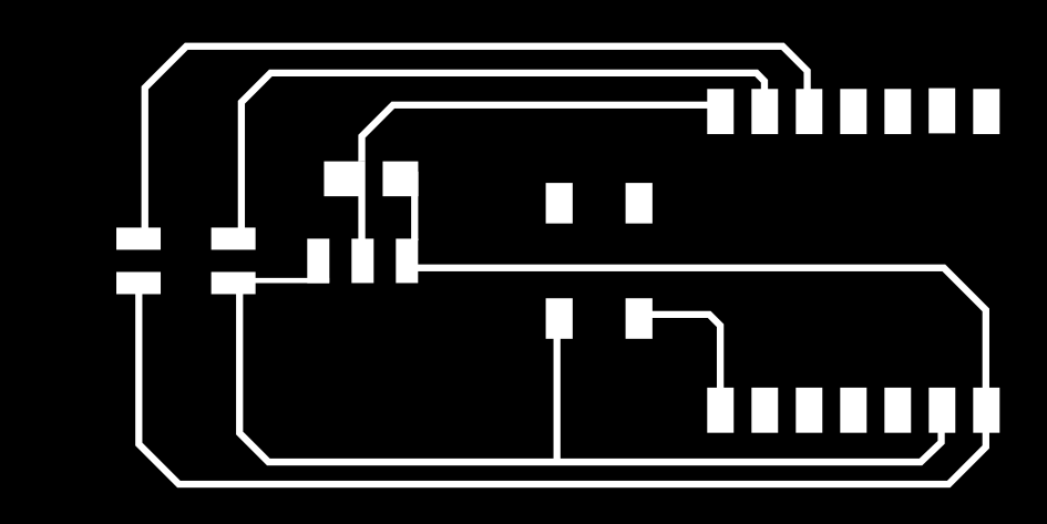
Now that I had all nodes working over I2C communicating with the XIAO ESP32 C3 master node on a breadboard I went ahead and designed the board for the XIAO master. Again, I had all the footprints readily available in old Inkscape projects so I copied the footprints I needed into a new document and routed everything. For those looking for footprints for any component I originally used SnapEDA to find the XIAO footprint. The first time I used the XIAO footprints I found the a bit small to solder properly so I edited the footprints to be a bit bigger for easier soldering.
Master node design Inkscape
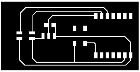
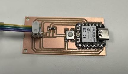
Master node board
The button will be used to change which sensor is displayed on the OLED, and the three empty footprints in the middle will be for the DS18b20 waterproof temperature sensor. I have not soldered the DS18b20 yet because I need to finish my electronics housing first.
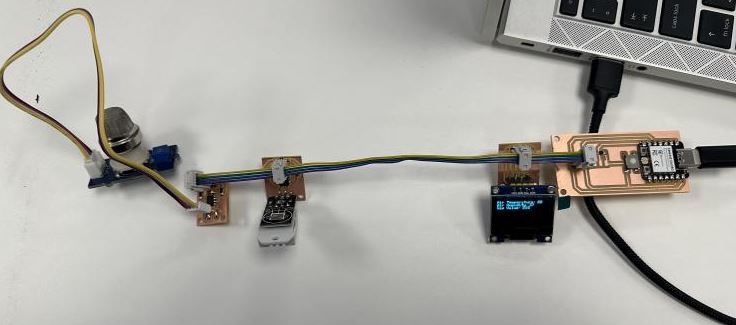
Electronics working!
DHT22 node
Using example codes from the internet I put together the code for all the components.
The code for the DHT22 node is as simple and easy to understand as I could make it.
										> for greater than and <

#define DHT_NODE_ADDRESS 1 // I2C address of the DHT22 slave module
#include <Wire.h>
#include <DHTStable.h>

#define DHTPIN 4  // DHT connected to ATtiny412 pin 4 (PA3)
#define DHTTYPE DHT22   // DHT 22  (AM2302)

DHTStable DHT; // initialize the DHT library

// Initialize the humidity and temperature variables
int humidity = 0;
int temperature = 0;

void setup()
{
	Wire.begin(DHT_NODE_ADDRESS); // join i2c bus with defined address
	Wire.onRequest(requestEvent); // register event
}

void loop()
{
	DHT.read22(DHTPIN); // Read DHT22 data.

	temperature  = DHT.getTemperature();
	humidity = DHT.getHumidity();

	delay(2000); /* Add 2 second delay in the loop */
}

void requestEvent() {
	Wire.write(temperature); // respond with message of 4 bytes
	Wire.write(humidity);    // respond with message of 4 bytes
}
MQ2 node
The code for the MQ2 node is very similar to the DhT22 node code.
Using the Wire library and DHTStable library I read the temperature and humidity and post the data to the master when requested
#define MQ2_NODE_ADDRESS 2 // I2C address of the MQ2 node module
#include <Wire.h>>
const int MQ2_PIN = 4; // Analog pin connected to MQ2 sensor

int gasValue = 0;

void setup() {
	delay(20000); // allow the MQ2 to warm up
	Wire.begin(MQ2_NODE_ADDRESS); // Set the I2C slave address (0x43 for MQ2 gas sensor)
	Wire.onRequest(requestEvent); // Register the request event handler
}

void loop() {
	// Read gas sensor data
	gasValue = analogRead(MQ2_PIN);
	delay(2000);
}

void requestEvent() {
	Wire.write(gasValue);
}
Using only the Wire library I read the gas level through analogRead and post the data to the master when requested,
Master node
The code for the Master node handles all requests to the sensor nodes as well as handling the reading for the DS18b20 waterproof temperature sensor. It also gathers all the data and displays the readings on the SSD1306 OLED display.
Using the Wire library I request data from the sensor nodes. The OneWire and DS18B20_INT libraries handle the waterproof sensor. Both Adafruit_ libraries are for the SSD1306 OLED display. This code snippet works and shows the basic readings and displaying of data. It is not the final version of the code. (for example no code to handle button inputs.)
#include <Wire.h> //For I2C

#include <OneWire.h> //for DS18B20
#include <DS18B20_INT.h> //for DS18B20

#include <Adafruit_GFX.h> //for SSD1306 OLED
#include <Adafruit_SSD1306.h> //for SSD1306 OLED

#define DHT_NODE_ADDRESS 1 // I2C address of the DHT22 node module
#define MQ2_NODE_ADDRESS 2 // I2C address of the MQ2 node module

#define ONE_WIRE_BUS 21 // Pin for DS18B20 sensor

#define SCREEN_WIDTH 128 // OLED display width, in pixels
#define SCREEN_HEIGHT 64 // OLED display height, in pixels

OneWire oneWire(ONE_WIRE_BUS); //for DS18B20
DS18B20_INT sensor(&oneWire); //for DS18B20

// Declaration for an SSD1306 display connected to I2C (SDA, SCL pins)
Adafruit_SSD1306 display(SCREEN_WIDTH, SCREEN_HEIGHT, &Wire, -1);

int temperature, humidity, gasValue, soilTemp;

void setup() {
	Wire.begin();        // join i2c bus (address optional for master)
	Serial.begin(115200);  // start serial for output

	sensor.begin(); //begin DS18B20 sensor

	if(!display.begin(SSD1306_SWITCHCAPVCC, 0x3C)) { // Address 0x3D for 128x64
	Serial.println(F("SSD1306 allocation failed"));
	for(;;);
	}
	delay(2000);
	display.clearDisplay();
}

void loop() {

	sensor.requestTemperatures(); // get temperature from DS18B20
	while (!sensor.isConversionComplete());  // (BLOCKING!!) wait until sensor is ready

	soilTemp = sensor.getTempC();

/*
	Serial.print("Temp: ");
	Serial.println(sensor.getTempC());
*/


	// Request data from the DHT22 sensor node
	Wire.requestFrom(DHT_NODE_ADDRESS, sizeof(int) * 2); // Request 2 integers
	if (Wire.available() >= sizeof(int) * 2) {

	temperature = Wire.read();
	humidity = Wire.read();

/*
	// Process and display the received data from DHT22
	Serial.print("DHT22 - Temperature: ");
	Serial.print(temperature);
	Serial.print(" °C, Humidity: ");
	Serial.print(humidity);
	Serial.println(" %");
*/
	}

	// Request data from the MQ2 gas sensor node
	Wire.requestFrom(MQ2_NODE_ADDRESS, sizeof(int)); // Request 1 integer

	if (Wire.available() >= sizeof(int)) {

	gasValue = Wire.read();

/*
	// Process and display the received data from MQ2 gas sensor
	Serial.print("MQ2 Gas Sensor - Gas Value: ");
	Serial.println(gasValue);
*/
	}

	display.clearDisplay();
	display.setTextSize(1);
	display.setTextColor(WHITE);
	display.setCursor(0, 0);
	// Display static text
	display.println("Air Temperature:");
	display.setCursor(100, 8);
	display.println(temperature);
	display.setCursor(0, 8);

	// Display static text
	display.println("Air Humidity");

	display.setCursor(100, 8);
	display.println(humidity);

	// Display static text
	display.setCursor(0, 16);
	display.println("Gas Value: ");
	display.setCursor(100, 16);

	// Display static text
	display.println(gasValue);
	display.setCursor(100, 32);

	// Display static text
	display.println(gasValue);
	display.display();


	delay(1000);
}
Using only the Wire library I read the gas level through analogRead and display the readings of all connected sensor to the OLED display.
Download DHT22 sensor node code
System Integration
Electric components housing
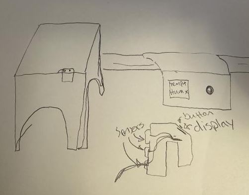
Now that I had all the electronics working I needed to make a housing for the electronics. I wanted to make a housing that would wrap around one of the sides of the CFT system. I want the display and button to be outside of the box while the three sensors are within the box.
I had a rough idea in my mind and sketched it out.
Electronics housing sketch
The electronics housing would be 3d printed so I started designing. Again, I wanted a simple design, in similar styla as the other 3d printed components, the support brackets.
Electronics housing Tinkercad
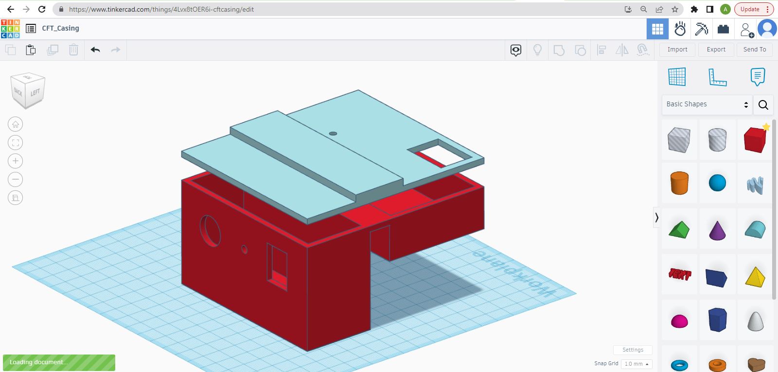
As before I made a simple blockout model in Tinkercad. I made rough measurements of the requirements for all the components and started modeling.
Electronics housing Blender
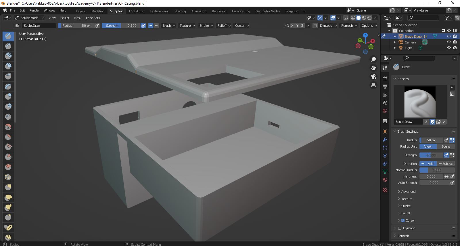
Using the rough blocked out model from Tinkercad I used Blender to add smoothness to the model.
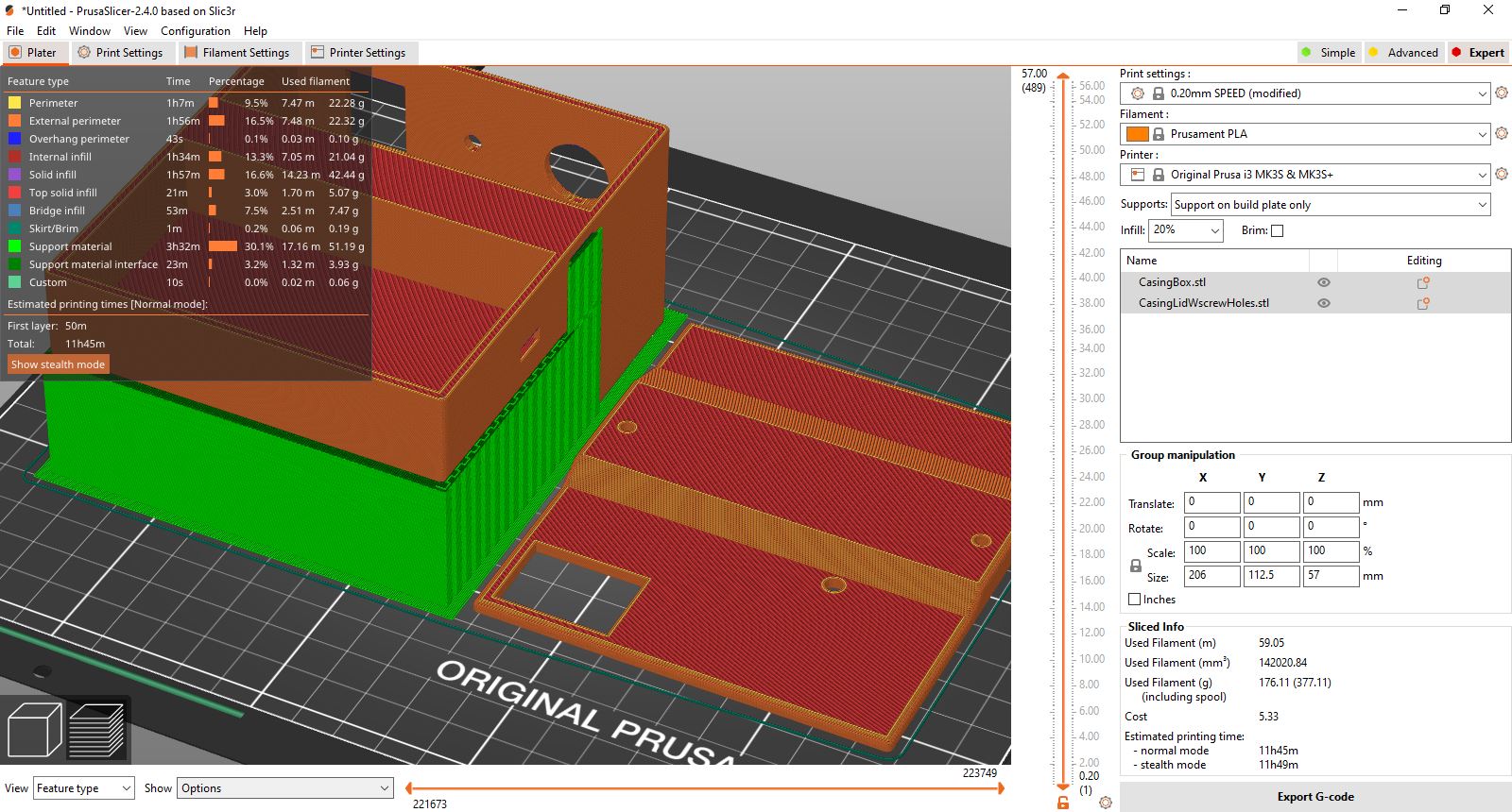
I brought the model into PrusaSlicer. Estimated time was little under 12 hours. I started the 3d prints and hoped for the best.
Electronics housing PrusaSlicer
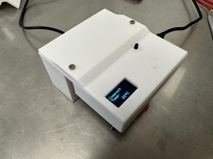
Electronics housing 3d print
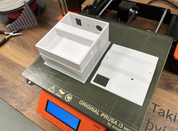
The 3d prints came out nice.
Download electronic housing 3d model .stl file
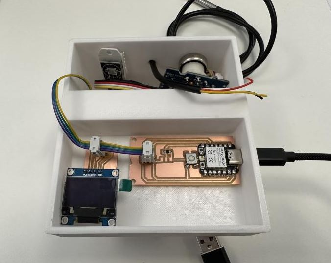
System integration
Electronics housing back
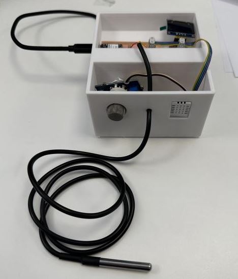
Electronics housing side
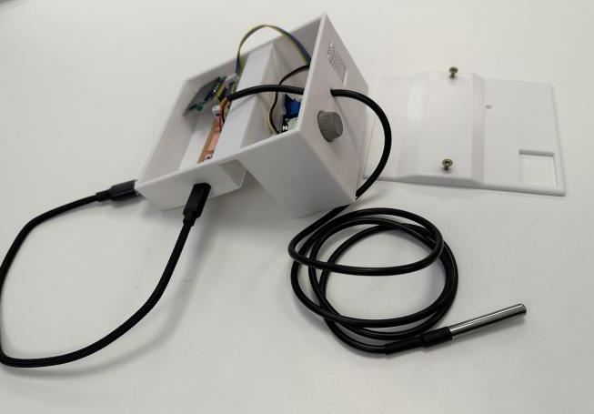
Electronics housing lid

ALl the electronics fit and line up perfectly,
Final Assembly
Now that I had all the components ready I could assemble the entire CFT system.
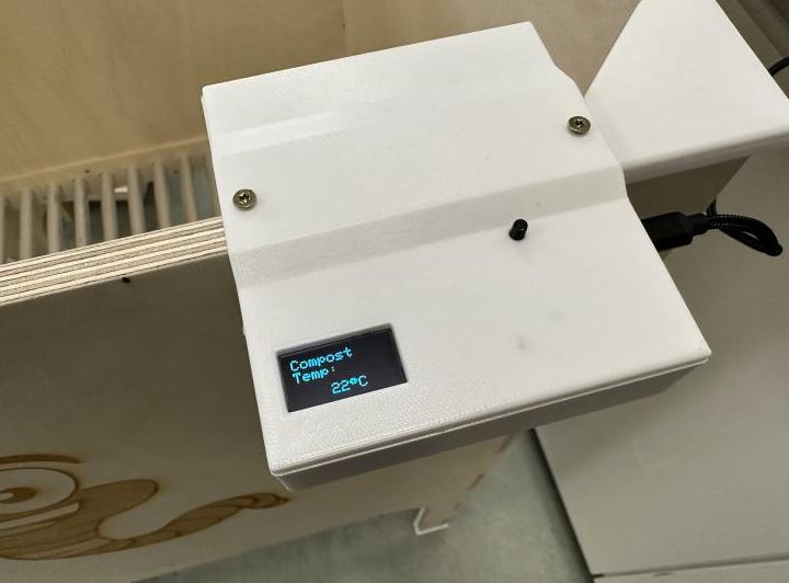
System integration
Sensor housing mounted
Testing everything
I had already tested all the sensors but with everything assembled I wanted to make sure everything worked.
Air Humidity sensor test (DHT22)
With a boiling cup of water I tested the humidity sensor.
Gas sensor test (MQ2)
Using a lighter I tested the gas sensor.
Waterproof temperature sensor test (DS18B20)
I used a cold glass of water to test the waterproof temperature sensor. If the temperature drops below a certain number the screen displays a warning.
I also tested the Air Temperature sensor (DHT22) but the air temperature change is so slow that it would have been too long for a video but rest assured the air temperature sensor (DHT22) works.
Bill of Materials
This is a list of materials used in this project.
- A sheet of plywood, 1.5m x 2.5m x 12 mm
- 3d filament for the support brackets, PETG
- Aluminum bars for the bottom
- XIAO Esp32C3 for the controller node
- Attiny412 for the sensor nodes
- DHT22 sensor
- DS18B20 sensor
- MQ2 sensor
- SSD1306 OLED display
- PCB boards
- Button
- Wires
License
“This work is licensed under a Creative Commons Attribution 4.0 International License”

Final Product Presentation
Video presentation
Presentation Slide