Non-solder breakout board
This project aims at connecting to every pin of a microchip without soldering it. The main use is pre-programming the chip so that it can be soldered onto a board that does not include programing pins to save space.
For now, there are two versions available:
- SOIC-14
- QFP-32
The project requires a PCB milling machine and a 3D printer.
Design
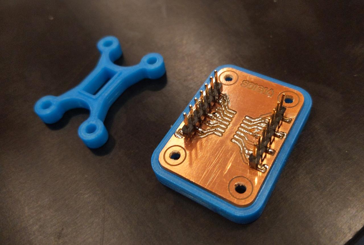
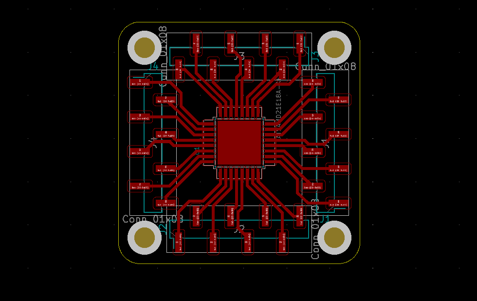
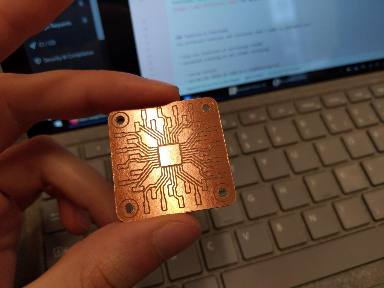
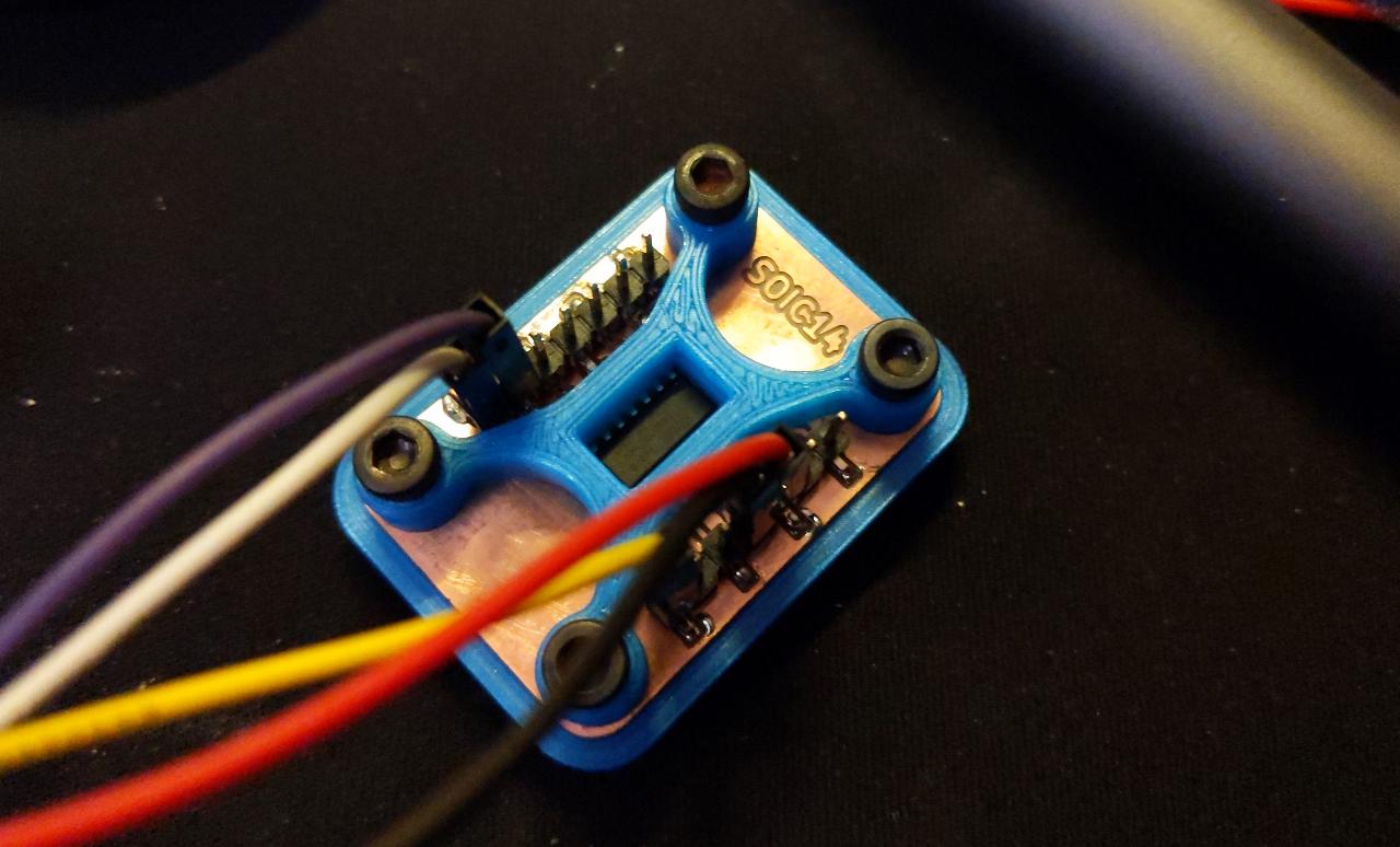
The board design is straightfoward; every pin is simply mapped to a Nx1 SMD header with 2.54mm pitch. TO make my job easier, I borrowed the schematic and footprint of an SAMD11C when designing the SOIC14 version. The holes in four corners are M3 holes for alignment with the 3D printed parts.

The QFP32 version is similar with all 4 sides populated with pins.
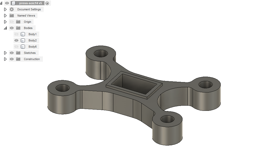
I transcribed the board dimensions in Fusion 360 and started drawing a clamp system attached to the M3 holes.
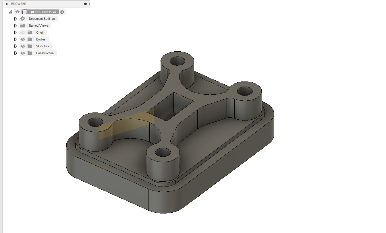
The bottom of the clamp has a lip that can press directly onto the chip’s pads to make sure they are touching the copper.
I also prepared a base with captive M3 nuts on the bottom so that the clamp can be screwed against it.
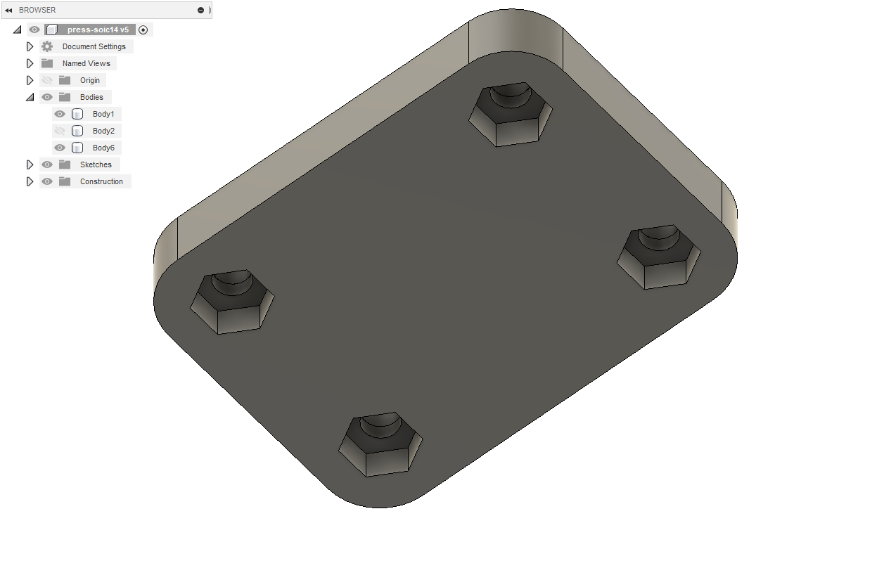
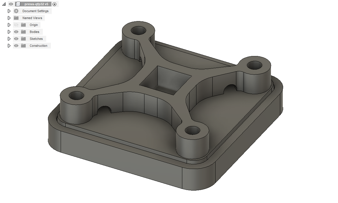
A QFP32 version is similarly designed, the only difference is little holes to avoid touching the pin rows, as space was very limited in this version.
Milling
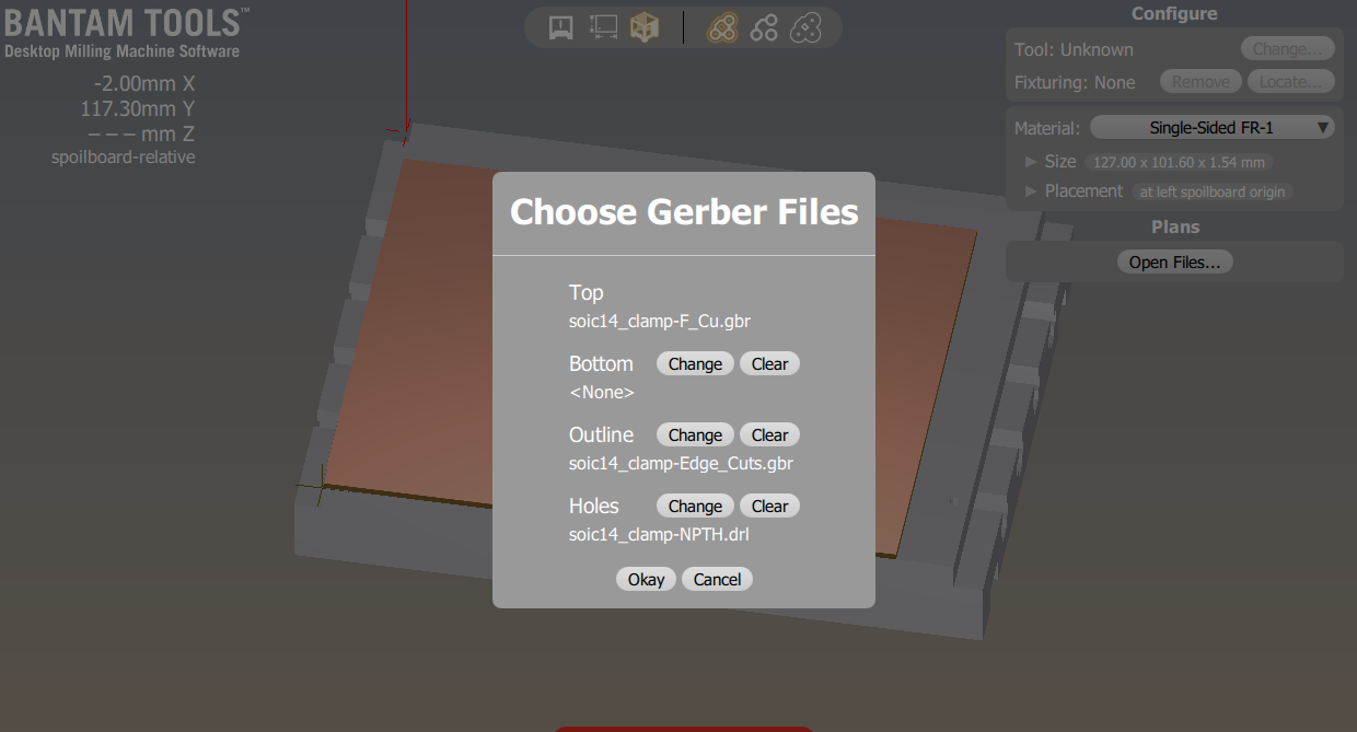
The Gerber files are exported from KiCad and important in the milling software, Bantam Tools in this case.
The traces are performed with a 1/64” (0.4 mm) flat end mill first.
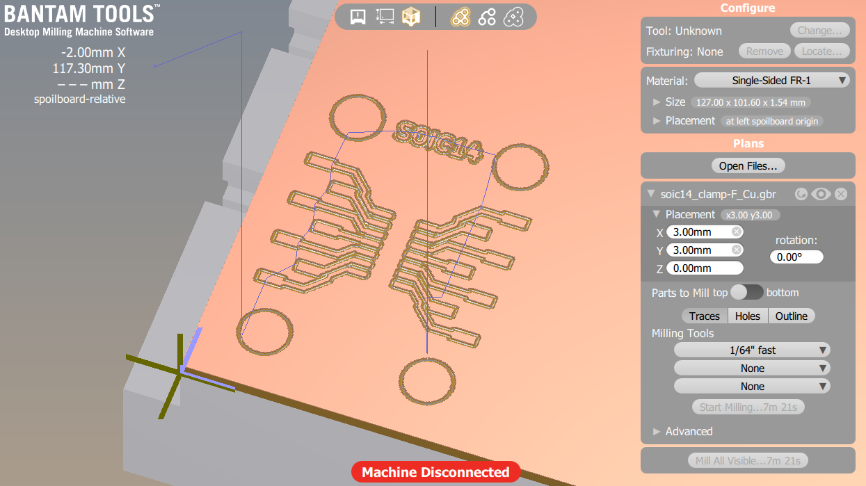
A 1mm flat end mill is then used for the M3 holes and the cutout.

The board came out perfectly on our Bantam dekstop milling machine.

The QFP32 version also came out perfect. Note that there is no label on this one, to save space.
3D printing
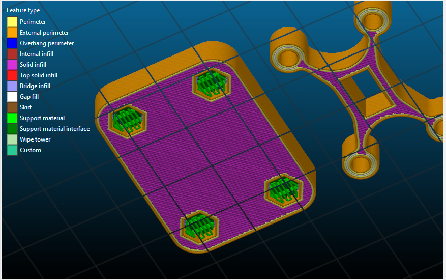
The Fusion 360 design files are exported as .stl and imported in Slic3r. It’s important to rotate the clamp so that the lip is facing upwards.

The bottom of the base requires support material because of the holes for the captive nuts.
The full print took around 30 minutes on a Prusa i3.

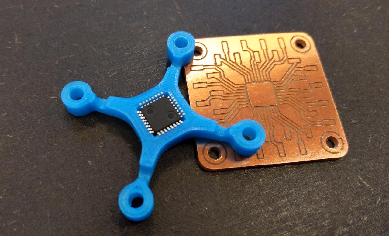
A quick test with a QFP32 chip confirms the alignment is good; the chip is locked on all sides.
Assembly
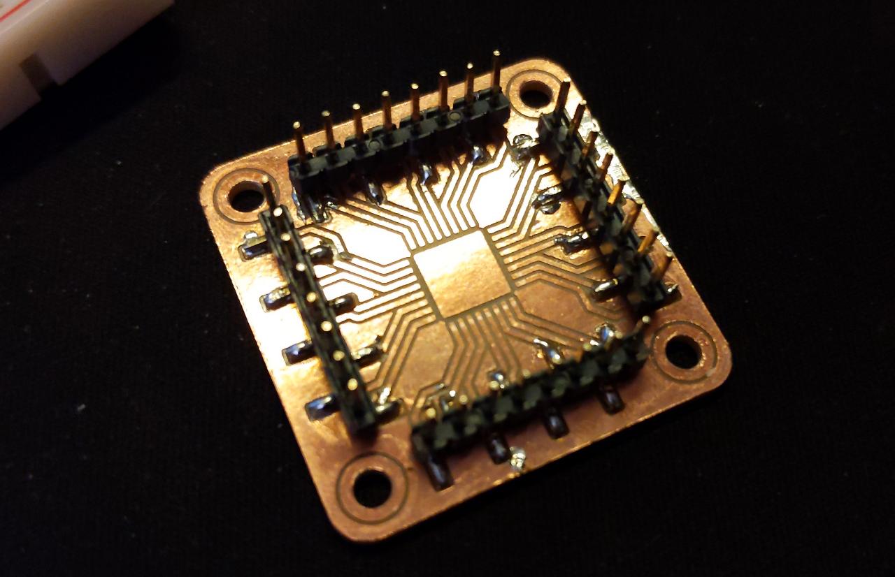
The 2.54mm headers are quickly soldered on each side of the board. I suggest putting solder on the entire trace to protect them against rust, but it’s important to put exactly the same width on each pad to prevent uneven pressure on the pads.
The QFP32 version requires a bit more work:
Finally, a SAMD11 is installed with screws on all corners, and programmed using its SWD pins. The entire process was successful and took around 2 minutes with an electric screwdriver.
License
This project is provided under the MIT License.