12. Output devices
This week is dedicated to getting more familiar with output devices. This includes any electronic device that can interact with the physical world. Searching through my components, I found a NEMA 17 stepper motor and a 16x02 LCD screen:
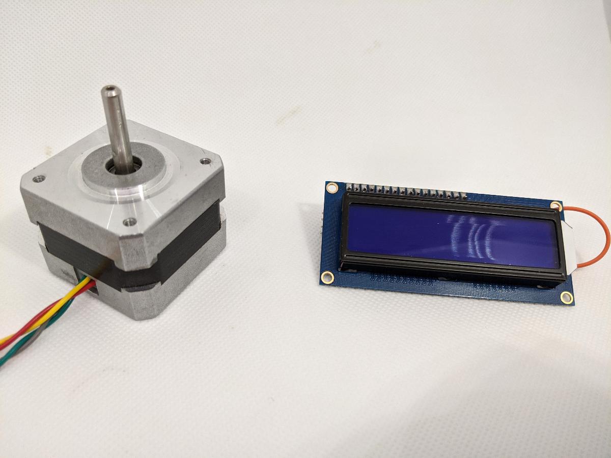
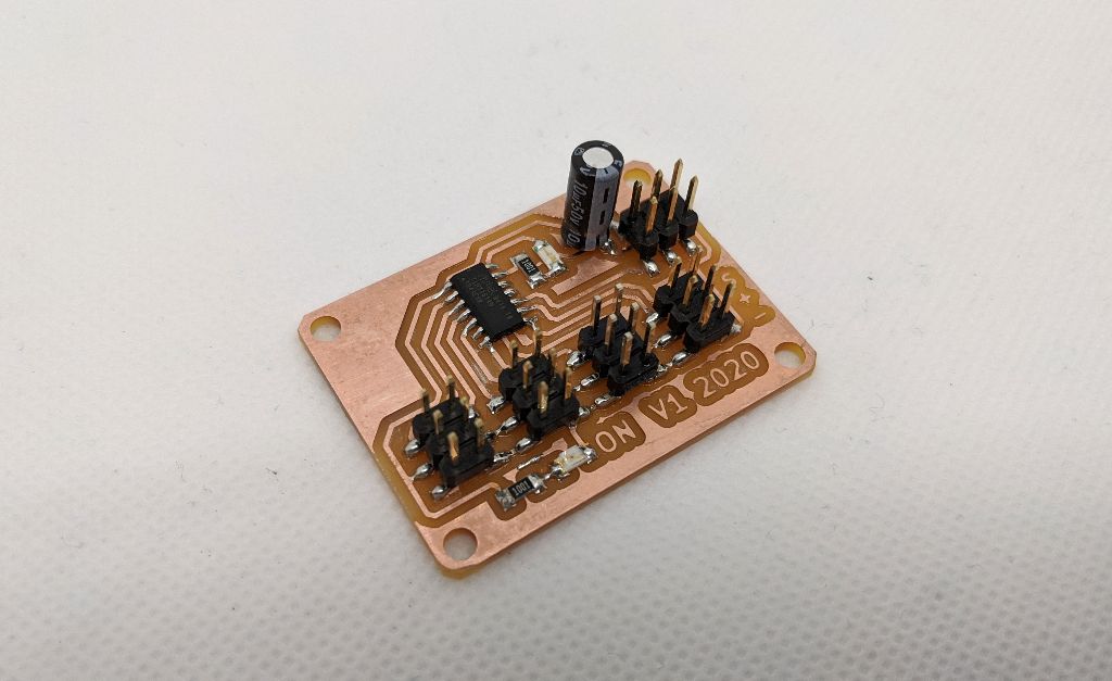
I will connect these to my ATtiny1614 board that I designed earlier: it can run at 5V and has 8 GPIO pins.
In the group assignment, we show how to estimate the power consumption of the stepper motor.
ATtiny1614 I2C screen
During the weeek on Embedded programming, I already showed how to connect this LCD screen to my ATtiny1614 board. The main idea is to use a I2C adapter, so that only 2 pins are needed:
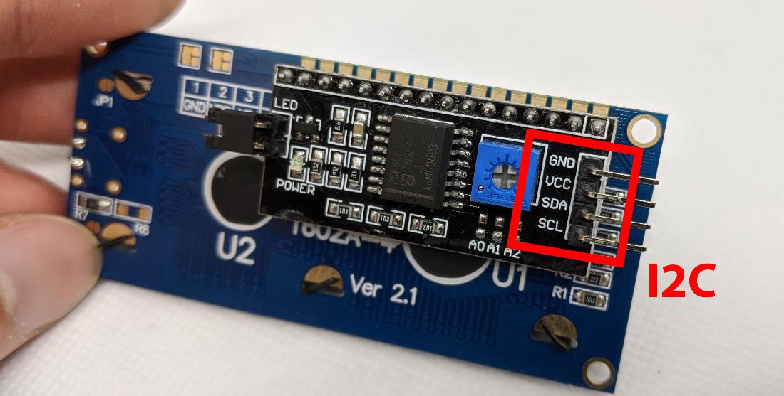
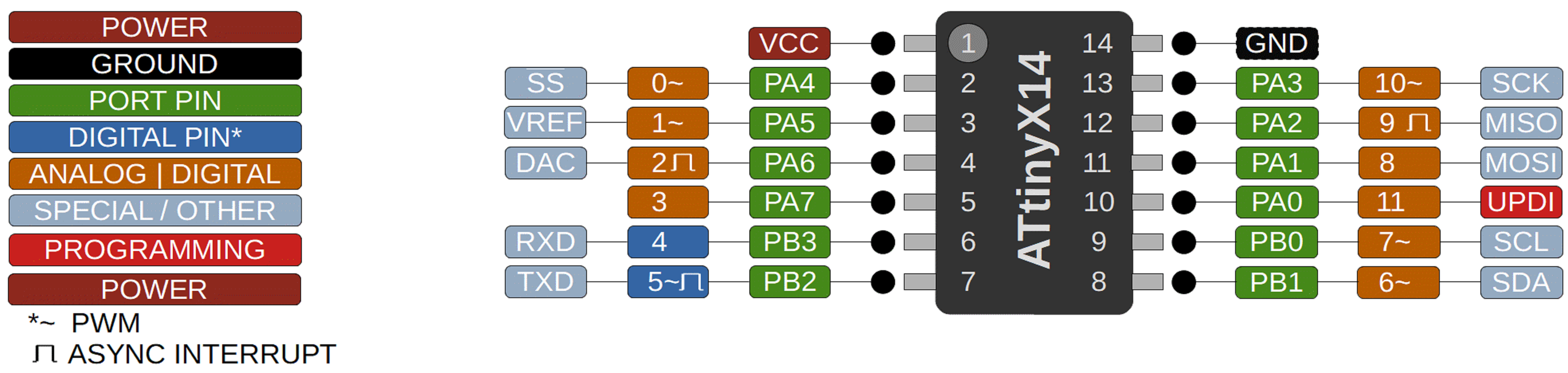
On the ATtiny1614, GPIO pins 6 and 7 can be used as an I2C port (source):
Thanks to the high level of abstraction that the Arduino IDE offers, I can use the LiquidCrystal_I2C library without any change; the I2C pin ports are already configured by the ATtiny1614 port of the Arduino system.
I use this simple code to test the screen:
LiquidCrystal_I2C lcd(0x3F, 16, 2);

void setup() {
  lcd.init();
  lcd.backlight();
  lcd.clear();
  lcd.setCursor(0, 0);
  lcd.print("Hello");
  lcd.setCursor(0, 1);
  lcd.print("fabacademy2020");
}

void loop() {
  delay(5);
}
The message should correctly show up on the screen. Messages up to 16 characters per line can easily be displayed in this way, and I will use the screen as a debugging tool in the following.

H-bridge and stepper motor
Stepper motors are driven by specific drivers, but in this case, I want to control each of its pin with my ATtiny1614. However, the current that needs to flow through the motor is non-negligible, so I use an H-bridge as an interface:
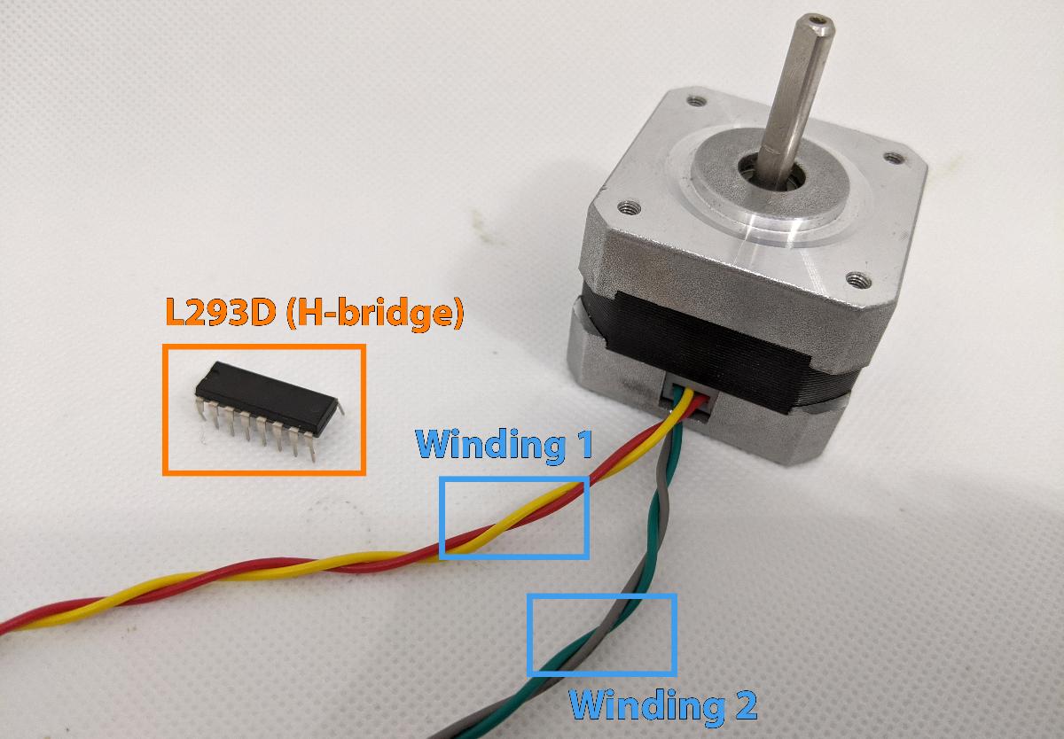
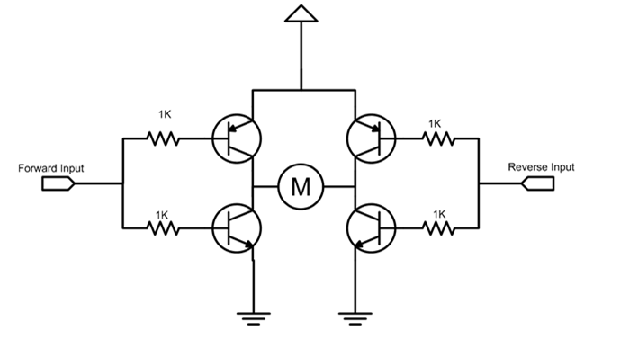
The L293D is an IC that embeds 4 half H-bridges. Combing two half H-bridges provides a full H-bridge, capable of driving a DC motor (or a stepper winding) in two directions (source):
A stepper motor remains fixed when a DC current is applied on each winding. To make it turn, we must apply a specific sequence of positive/negative voltages on each winding (source):
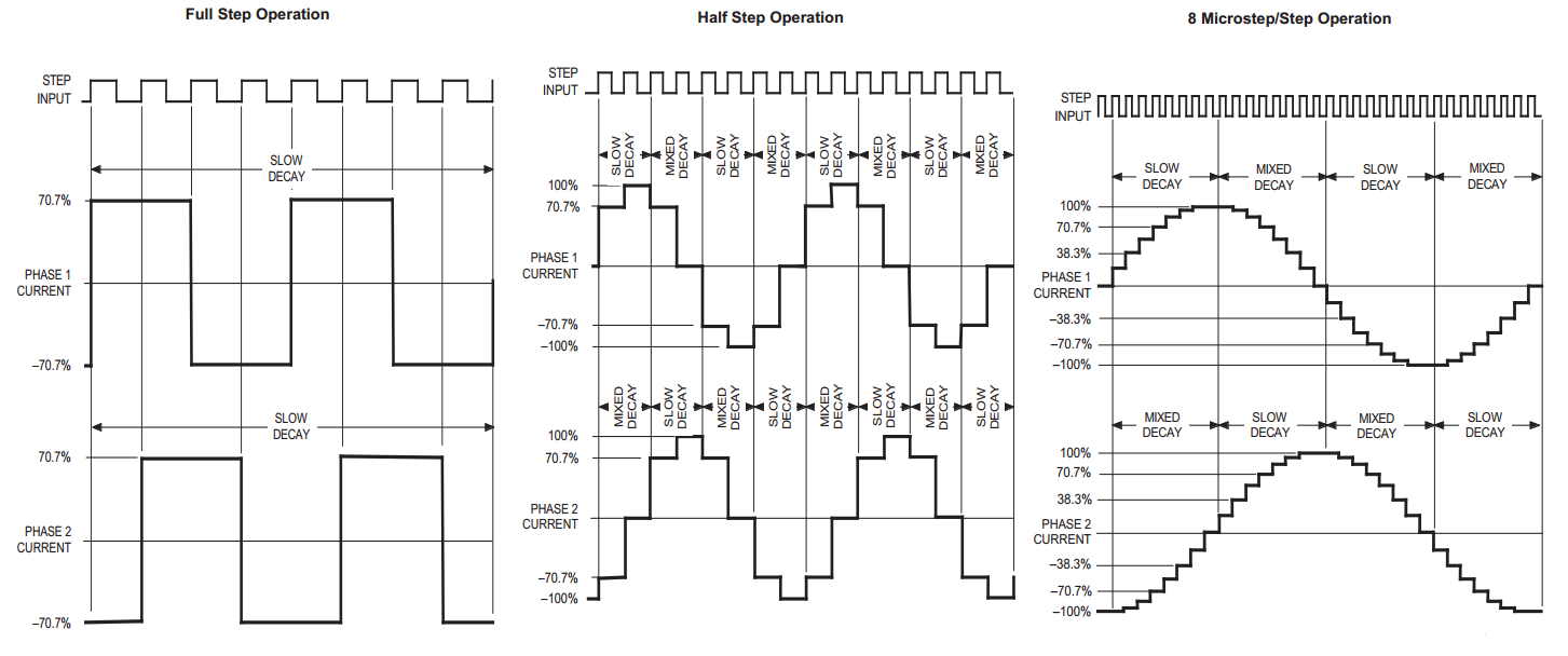
In this case, we will focus on full-step operation, as it only requires digital operations. This motor has 200 steps per revolution, yielding 1.8 degrees of precision. A quick measurement of the winding resistance provides a value of R \approx 35\Omega:
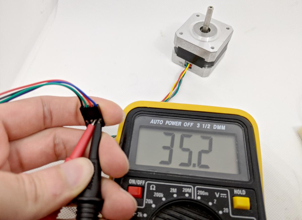
This shows that driving the windings with 5V is OK, as it results in a current of about 142 mA, well below the L293D ratings. When connecting a motor to the H-bridge, it is important to add protection diodes. They will prevent voltage spikes e.g. when the motor suddenly stops.

I decided to quickly draw a board in EAGLE to handle this functionality. Here is the schematic:
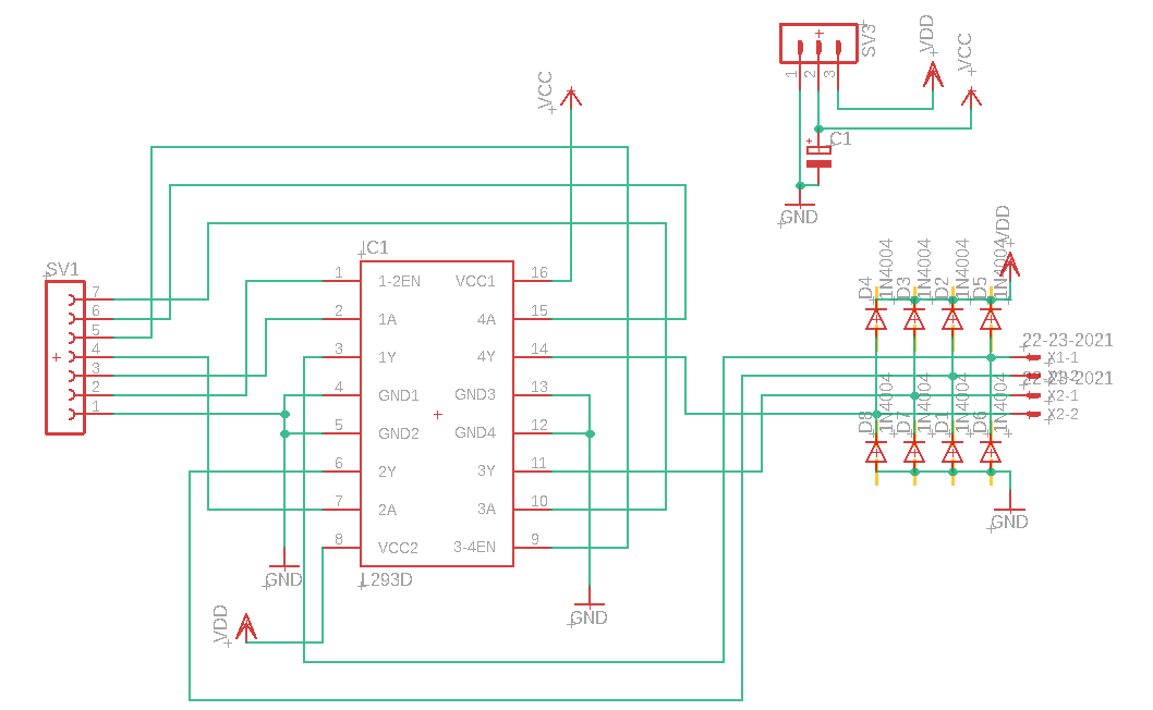
The board only uses DIP packages, as they are sometimes more popular in high-current applications. Unfortunately, I could not yet produce this board as I don’t have current access to my FabLab. You can find the design files at the end of this page.

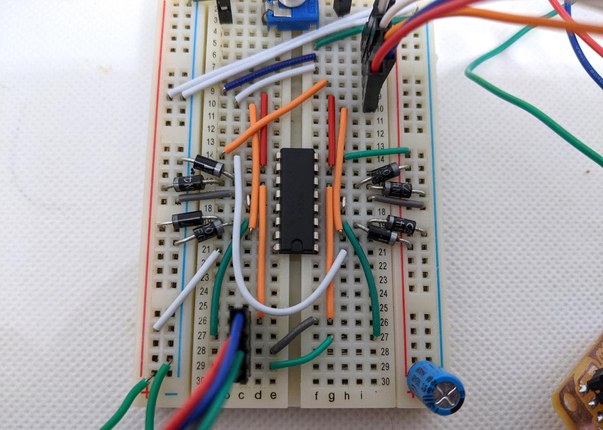
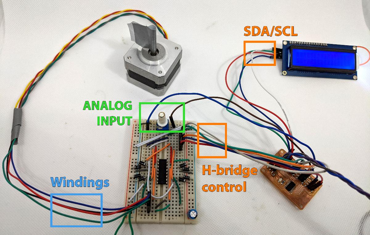
Instead of my custom PCB, I had to use a breadboard to test the idea. The result is a bit messy:
For this little project, I add a potentiometer to control the motor rotation, and the I2C LCD screen to display feedback. The H-bridge takes 5 digital outputs on my ATtiny1614 (4 gates + 1 enable pin). By pulling down the enable pin to 0V, I can disable the H-bridge and disconnect the motor, which is useful for power management.
In the Arduino code, I decided to try out timer interrupts so the driving of the motor will not be affected by using the screen. In the setup(), I add the following block to setup timer B of the ATtiny1614:
// disable interrupts
cli();
// setup Timer B
TCB0.CTRLA = TCB_CLKSEL_CLKTCA_gc;
TCB0.CTRLB = TCB_CNTMODE_INT_gc;
TCB0.CCMP = 0x0AFF;
TCB0.INTCTRL = TCB_CAPTEI_bm;
TCB0.CTRLA |= TCB_ENABLE_bm;
// enable interrupts
sei();
Using timer B will break support of analogWrite(), but this is not important in this project. I add the following function, which is registered as a timer B interrupt:
static int cycle_1[] = {1, 0, 0, 1};
static int cycle_2[] = {1, 1, 0, 0};

int i = 0;

ISR(TCB0_INT_vect) {
  i = (i+1)%4;
  digitalWrite(PIN_1A, cycle_1[i]);
  digitalWrite(PIN_1B, 1-cycle_1[i]);
  digitalWrite(PIN_2A, cycle_2[i]);
  digitalWrite(PIN_2B, 1-cycle_2[i]);

  // reset interrupt
  TCB0.INTFLAGS = TCB_CAPT_bm;
}
Applying this sequence will make the motor turn in a continuous way. Here is the full code:
#define PIN_1A 0
#define PIN_1B 1
#define PIN_2A 4
#define PIN_2B 5
#define PIN_EN 3

static int cycle_1[] = {1, 0, 0, 1};
static int cycle_2[] = {1, 1, 0, 0};

int i = 0;

int sign(int value) {
  return int((value>0)-(value<0));
}

ISR(TCB0_INT_vect) {
  i = (i+1)%4;
  digitalWrite(PIN_1A, cycle_1[i]);
  digitalWrite(PIN_1B, 1-cycle_1[i]);
  digitalWrite(PIN_2A, cycle_2[i]);
  digitalWrite(PIN_2B, 1-cycle_2[i]);

  // reset interrupt
  TCB0.INTFLAGS = TCB_CAPT_bm;
}

void setup() {
  // setup pins
  pinMode(PIN_1A, OUTPUT);
  pinMode(PIN_2A, OUTPUT);
  pinMode(PIN_1B, OUTPUT);
  pinMode(PIN_2B, OUTPUT);
  pinMode(PIN_EN, OUTPUT);
  digitalWrite(PIN_EN, HIGH);

  // disable interrupts
  cli();
  // setup Timer B
  TCB0.CTRLA = TCB_CLKSEL_CLKTCA_gc;
  TCB0.CTRLB = TCB_CNTMODE_INT_gc;
  TCB0.CCMP = 0x0AFF;
  TCB0.INTCTRL = TCB_CAPTEI_bm;
  TCB0.CTRLA |= TCB_ENABLE_bm;
  // enable interrupts
  sei();
}

void loop() {
  delay(5);
}
The motor starts turning. I can control the speed by changing the frequency of timer B. I settle for a reasonable speed that does not cause a stalling of the motor. Timer B has a default prescaler of 64, so a compare value of 0x0AFF=2815 gives the following step frequency:
With a stepper motor of 200 steps per revolution, we should get a revolution every 1.8 seconds. The following experiment confirms this:
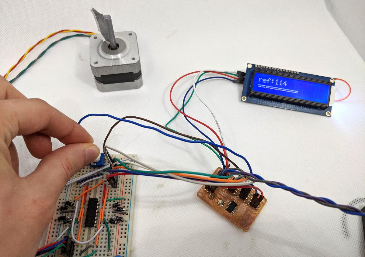
In the full project, I add a reading of the potentiometer that controls a reference position for the motor. The motor is then fed +1 or -1 steps to have a simple control loop that follows the reference. This turns the stepper motor in some kind of overly-complex servo motor. On the LCD screen, I display a progress bar for the reference (0-200). You will find the full code at the end of this page.
Here is a video of the project working: