18. Mechanical design and machine design
This week brings our final assignment for this year’s fabacademy. The objective is ambitious: the target is to design and build a machine, then to program and automate it.
Because our team is composed of only 2 students, we simplified tasks to their most basic form: I handled the entire electronics & programming, while Robin designed and produced all mechanical components. We agreed very early on what kind of motor we would use, and the kind of motion they would perform. Knowing this, I could focus solely on controlling those motors with novel electronics.
Our machine
The machine we built is a flexible XY motion system, pushed by two motors hidden inside. The actual motion is produced by spirals pushing against the main frame, as shown later.

Here is the type of motion we managed to produce:
You can find more details about this project in the group documentation. In this page, I will focus on explaining the electronics system I designed to reach that result.
Stepnode: a building block for machine control
Inspired by existing projects and dicussions with my instructors, I wanted to incorporate two intersting principles in my design:
- Each motor must be controlled by an individual board, similar to how Gestalt nodes work. Adding a node should be plug-and-play and work straight away.
- The computer should control the machine in realtime using bare minimal messages on a UART line (1-2 bytes per instruction). This is very similar to the Urumbu project.
Those two ideas are mutually beneficial: controlling several nodes with a single byte instruction is feasible if done right.
I propose the following solution:

Each stepnode is a minimalist stepper motor controller based on a A4988 pololu module and a small ATtiny microcontroller (more details in the next section). The nodes are receiving a UART byte on one end, and forwarding a slightly modified message on the other end. They form a closed-loop daisy-chain, which is similar to how token rings used to operate. The last forwarded message goes back to the USB node, which simply sends it back to the computer. This means all encoding/decoding must be performed by the computer.
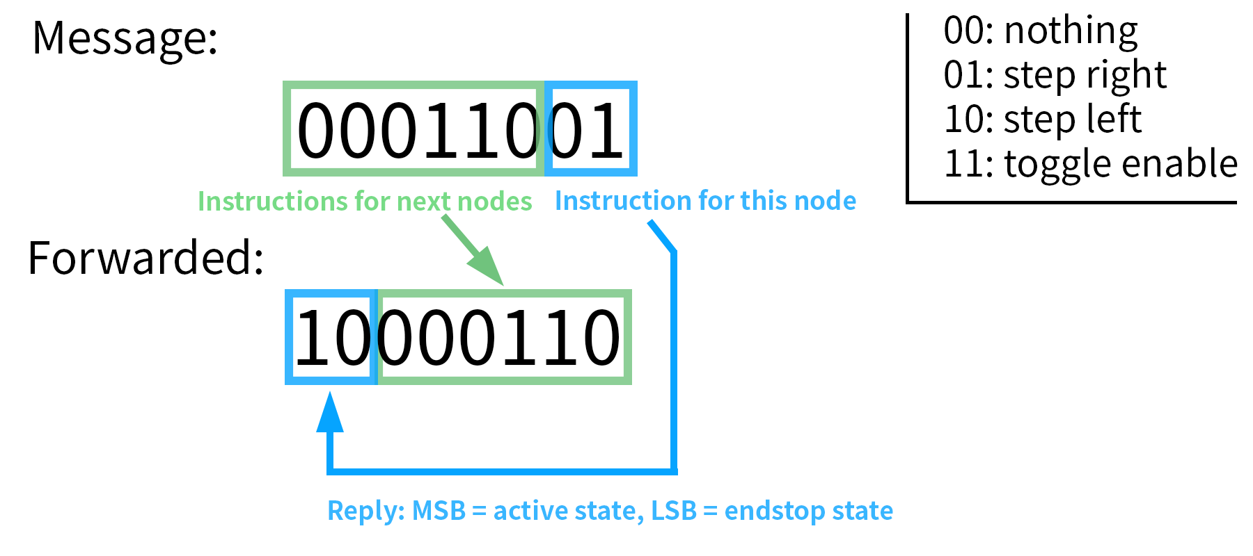
There is no addressing system to avoid any overhead. Instead, each node shifts its message to the right so that the next nead can read the Least Significant Bits (LSB) and repeat this procedure. The reply of a node is appended at the left, filling the void that was created. The limit in number of nodes is how many bits are comprised in a complete message.
In our case, we have only 2 motors, and we implement no checksum or sequence numbering for simplicity’s sake. Using a single byte and 2 bits instructions, we can communicate up to 4 nodes, which is already enough for a 3D printer for instance. Here is the type of message that is received/forwarded by a node:
The next section presents some implentations of the stepnode concept. This is still experimental and can be improved further, but my proof-of-concept is very promising as shown later.
Design and manufacturing
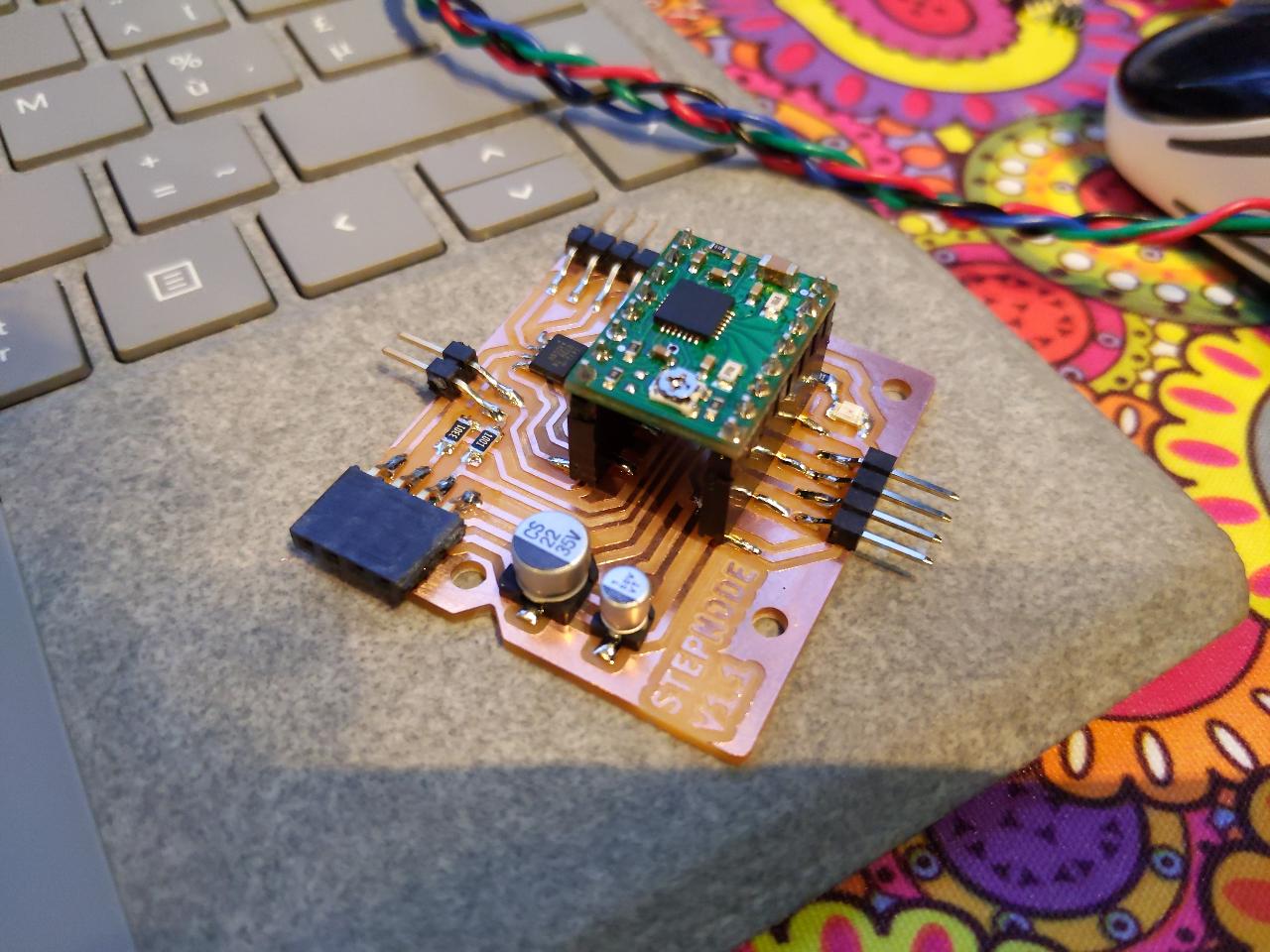
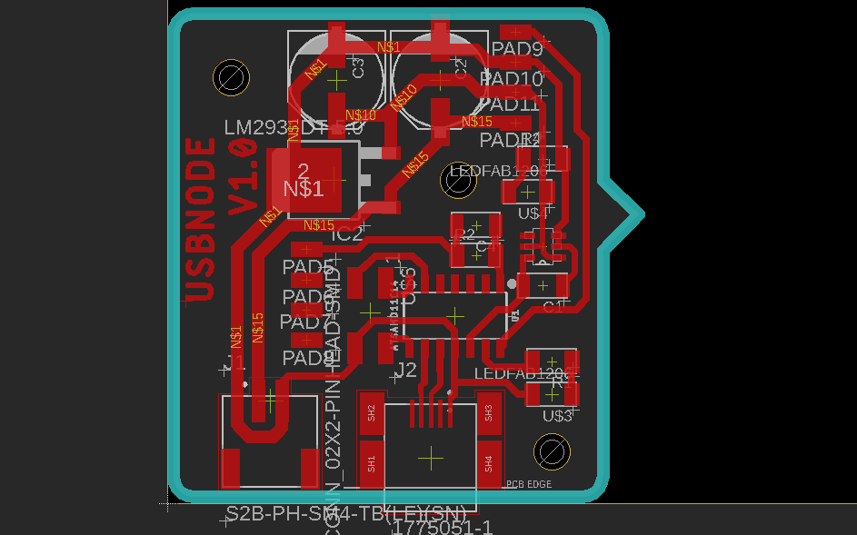
In my first design attempt, I picked an ATtiny1614 as the microcontroller for each node. I mapped all unused pins to a 3-row header, similar to what I showed during the electronics design week. The idea was to allow several endstops or other functionalities (servos etc.).
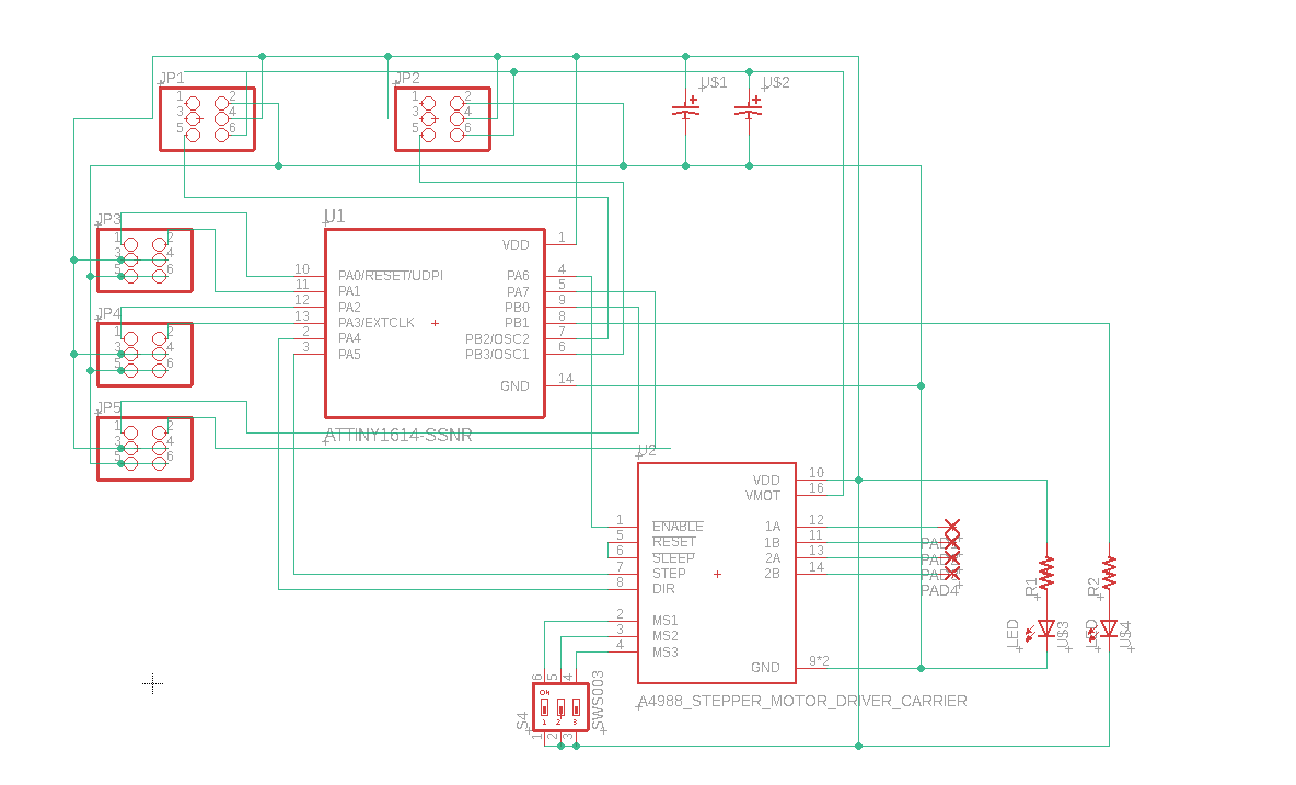
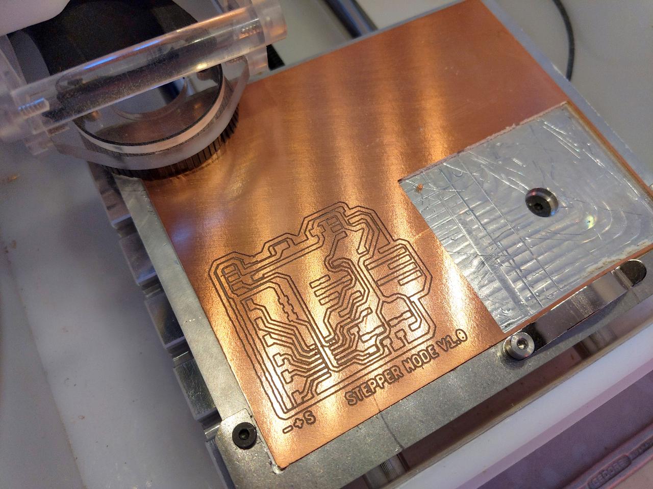
Due to these extra pins, and the microstep selection switch I placed next to the A4988 stepper driver, the board ends up being pretty chunky.
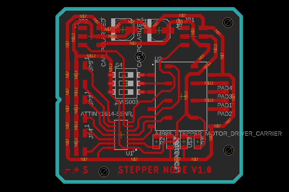
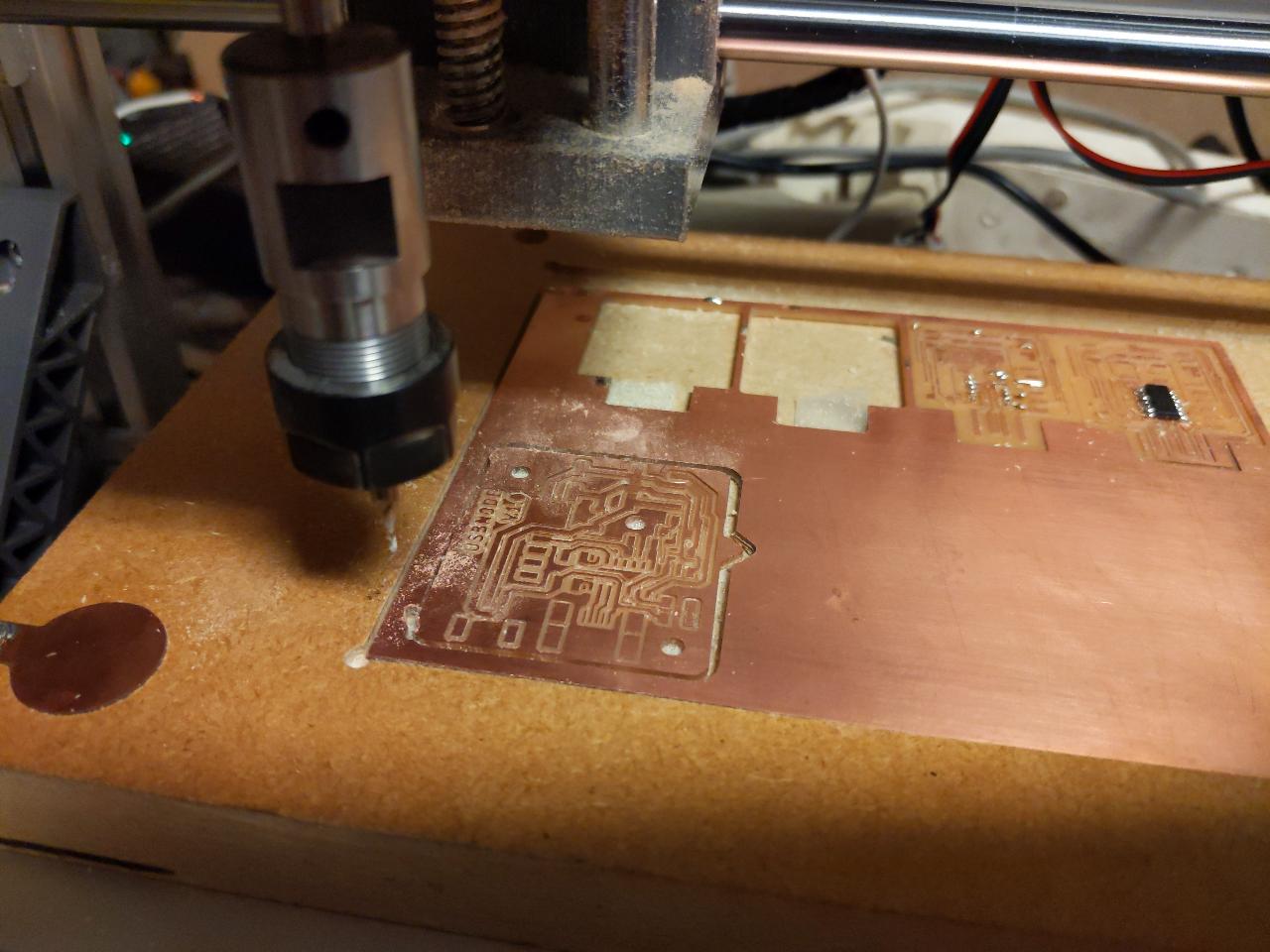
I milled it on the lab’s Bantam tools desktop CNC, with the same settings I discussed during the electronics production week.
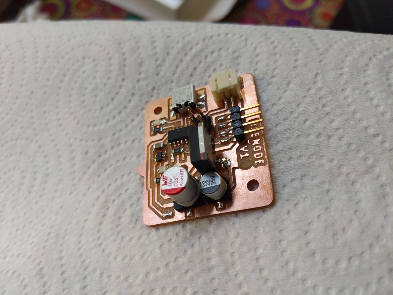
Stuffing the board caused no specific issue and took about 30 minutes.

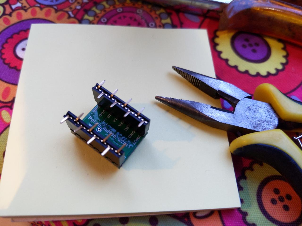
Because my stepper driver was already soldered on male pins, I had to put female headers on my board. I made it SMD-compatible by flattening the pins in an alternating pattern. This ensures rigidity on both sides.
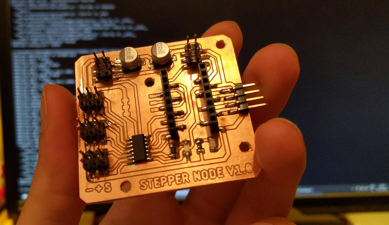
The finished product fits in a hand. The headers on the top left and right are the input/output buses, respectively.
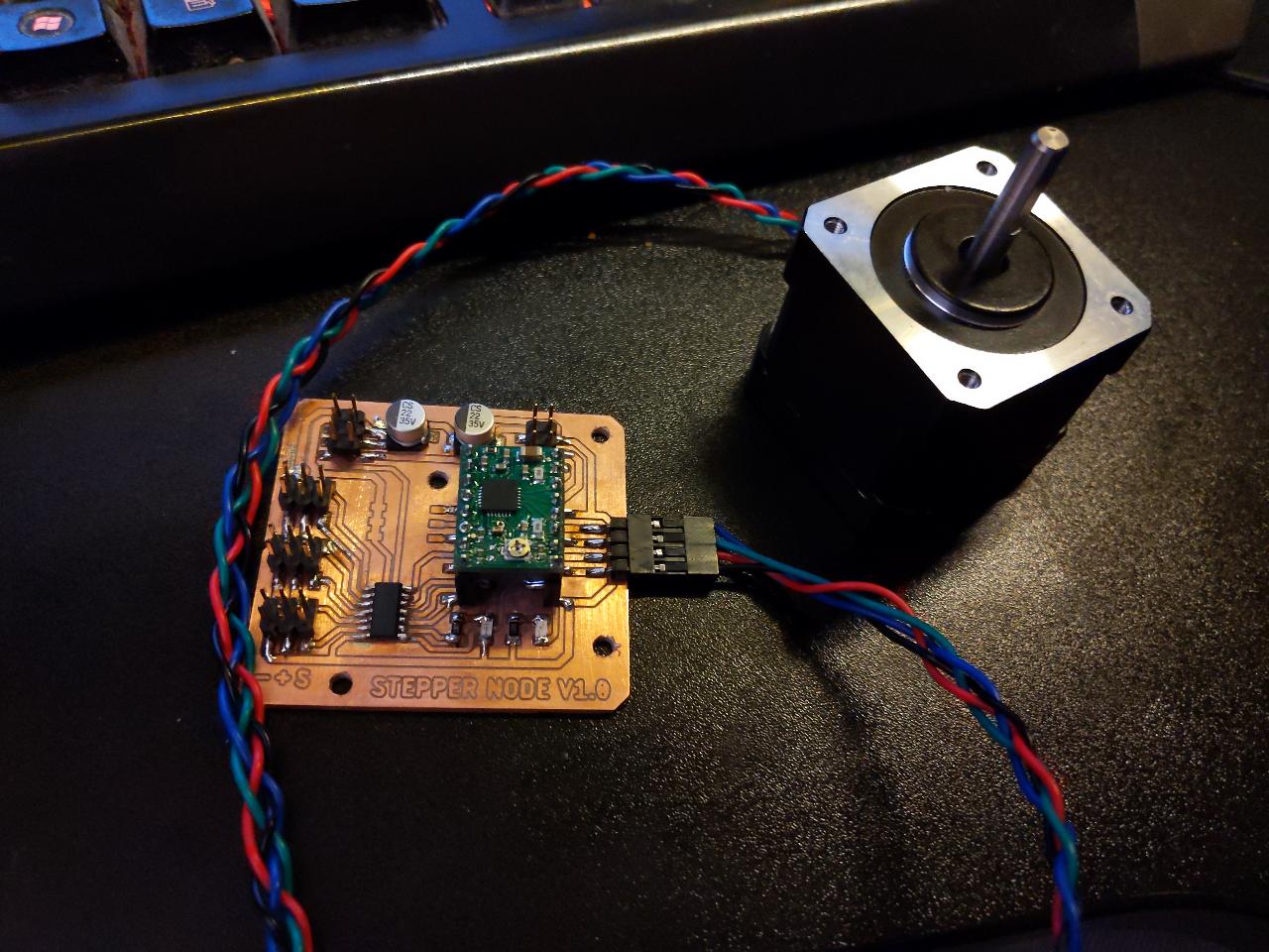
I connected a NEMA17 stepper motor, and it worked OK. The important step is to adjust the current limit by turning the potentiometer on the A4988 (more details here).
Unfortunately, I ended up frying the ATtiny1614 by inserting the stepper driver while the power supply was on. For some reason, this somehow injected current in the chip, and all its GPIO pins were constantly pulled-up. There was no easy way to re-program it.
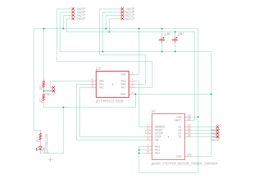
Rather than trying to fix this board by replacing the chip, I decided to re-design the board. As we had limited supplies in ATtiny1614, I switched to a simpled ATtiny412. This one has only 8 pins:
- 2 power pins
- 2 UART pins
- 1 UPDI pin for programming
- 3 remaining GPIO pins
This very strict budget forced me to keep my design minialist. One problem is that the stepper driver needs 3 pins on its own, which leaves no GPIO pin for connecting the endstop. I found a brilliant post on this page, suggesting to use the UPDI programming pin as an additional input. You can re-map this pin to a different use, but the chip cannot be re-programmed easily the next time. Instead, you can use this pin as an analog input, which requires no re-mapping.
I include a simple voltage divider on the endstop pin, such that a closed-circuit will yield 3.8V on the UPDI pin. This is high enough to not trigger a reset of the chip, happening approximately below 2.5V.
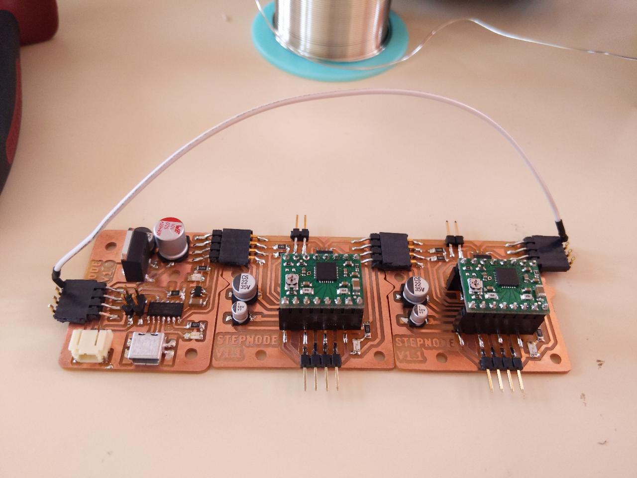
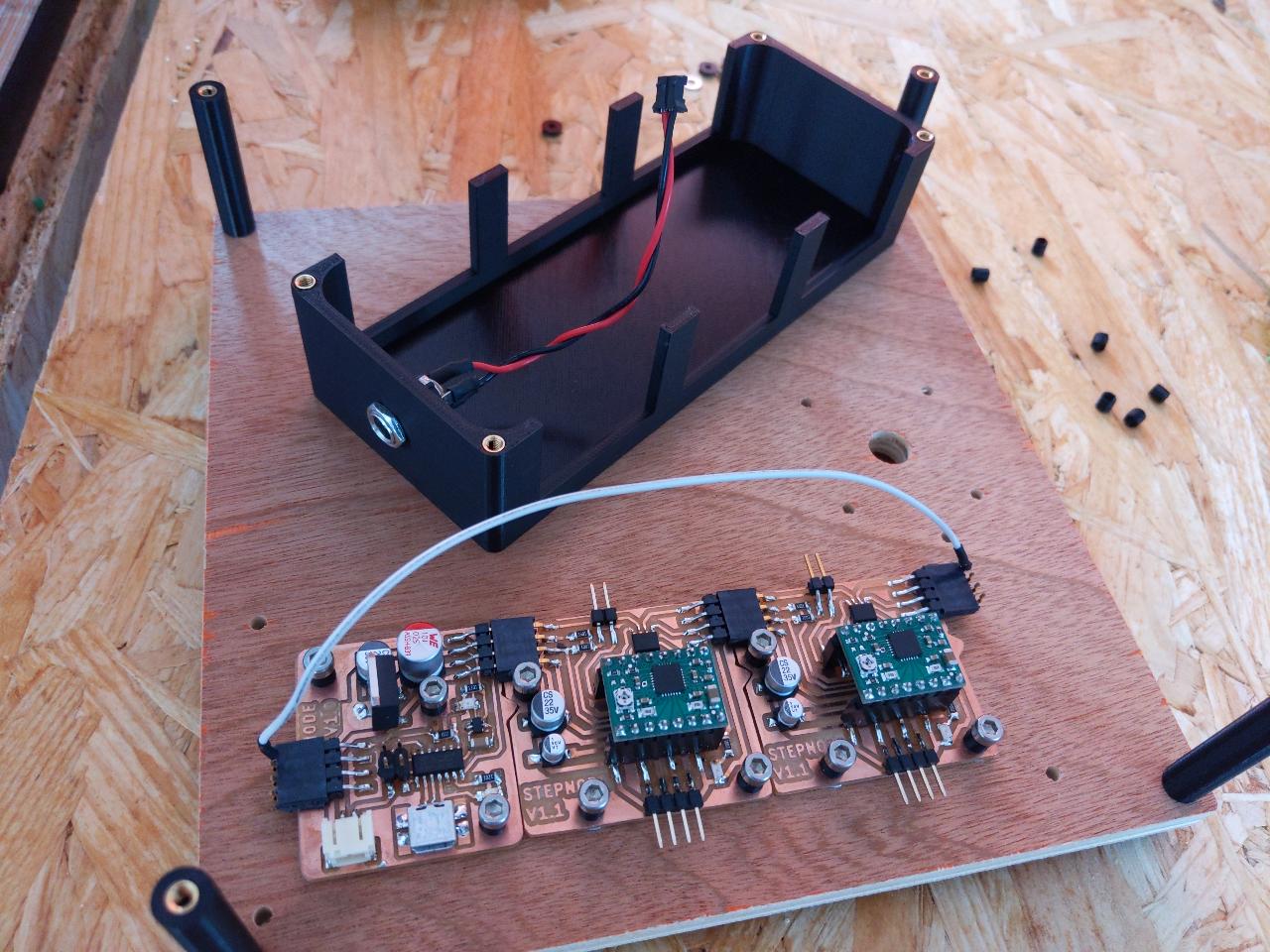
In this new design, I wanted the boards to be truly plug-and-play: each node can be connected on the right side of another node. You can see pads on the top side of the board, where I will solder male/female horizontal headers. I also include a small triangle in the board shape so that there is only 1 correct way of connecting them.
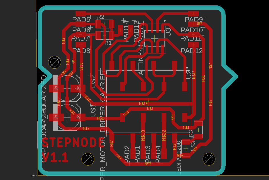
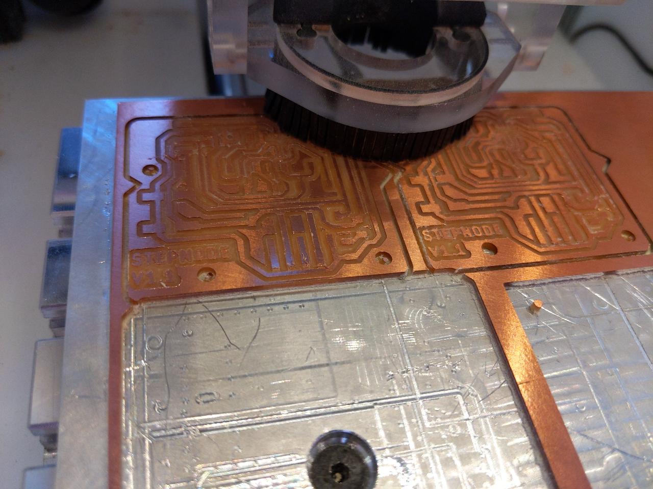
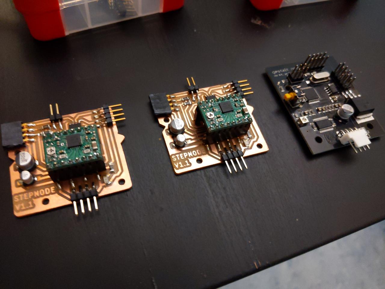
I milled 2 copies on the lab’s Bantam tools machine.
I started by soldering the chip and the input/output connectors.
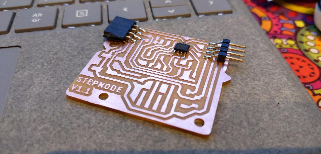
The final board is not over-sized, as the previous version was. You can now see the motor pins and endstop pins on the sides.
This board is about the same size as a gestalt node.
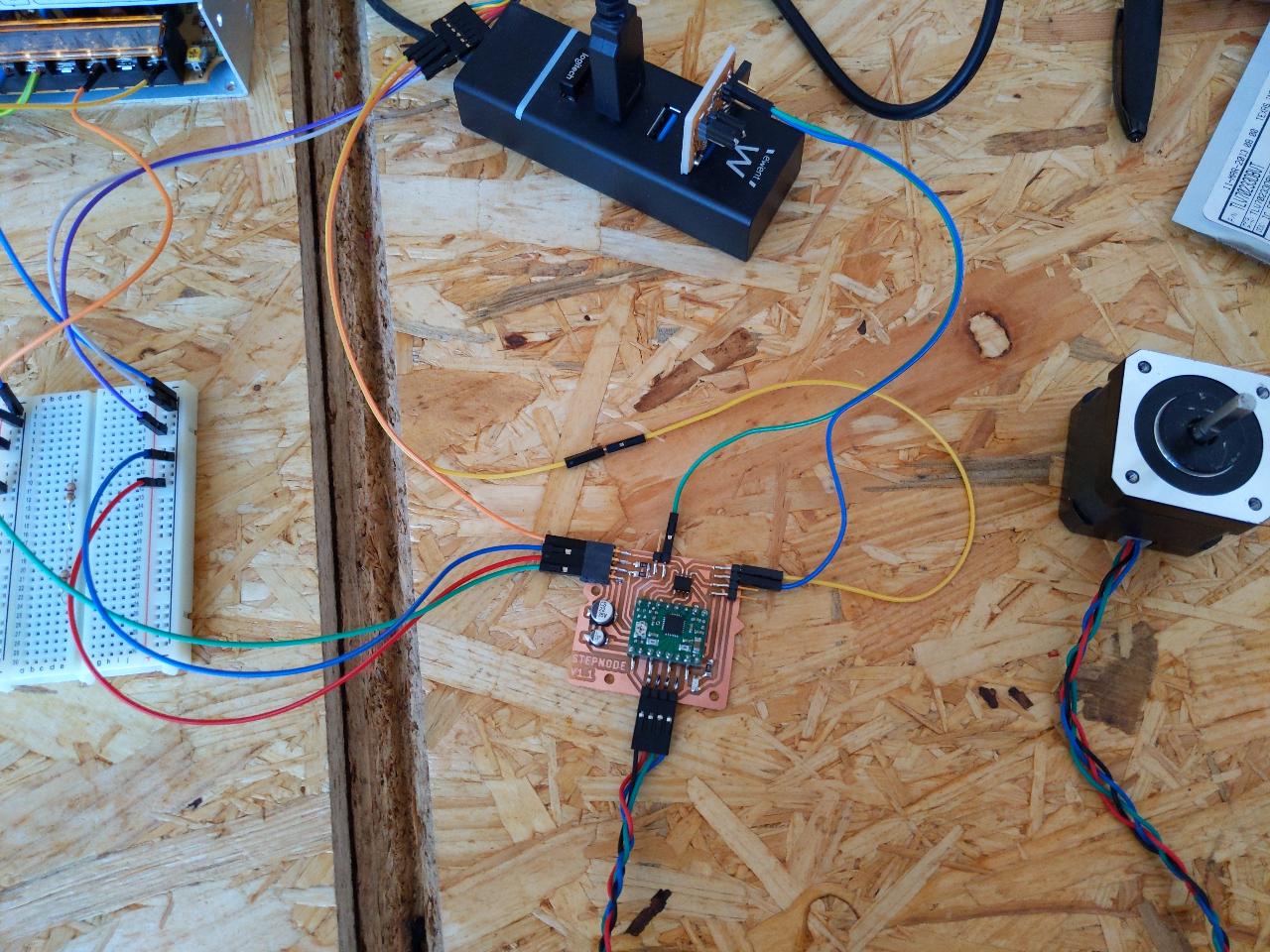
To program a board whithout the USB node being finished, I had to use a FTDI UART adapter. I program the ATtiny with my own UPDI programmer.
The following code implements the discussed protocol in a naïve but effective way:
#define PIN_DIR 2
#define PIN_STEP 3
#define PIN_ENABLE 4
#define PIN_ENDSTOP 5

char rcv;
char cmd;
char s_enable = true;
char s_endstop = false;

void setup() {
   pinMode(PIN_ENABLE, OUTPUT);
   digitalWrite(PIN_ENABLE, LOW);
   pinMode(PIN_DIR, OUTPUT);
   pinMode(PIN_STEP, OUTPUT);
   Serial.begin(115200);
}

void loop() {
  char cmd;
  char snd;
  if (Serial.available()) {
    rcv = Serial.read();
    cmd = rcv & 0b11;
    if (cmd != 0b00) {
      if (cmd == 0b11) {
        s_enable = !s_enable;
        digitalWrite(PIN_ENABLE, s_enable ? LOW : HIGH);
      } else {
        digitalWrite(PIN_DIR, cmd & 0b01 ? LOW : HIGH);
        digitalWrite(PIN_STEP, HIGH);
        delayMicroseconds(50);
        digitalWrite(PIN_STEP, LOW);
      }
    }
    snd = ((rcv >> 2) & 0b00111111) | (s_endstop << 6) | (s_enable << 7);
    Serial.write(snd);
  }
  int val = analogRead(PIN_ENDSTOP);
  s_endstop = val < 850;
}
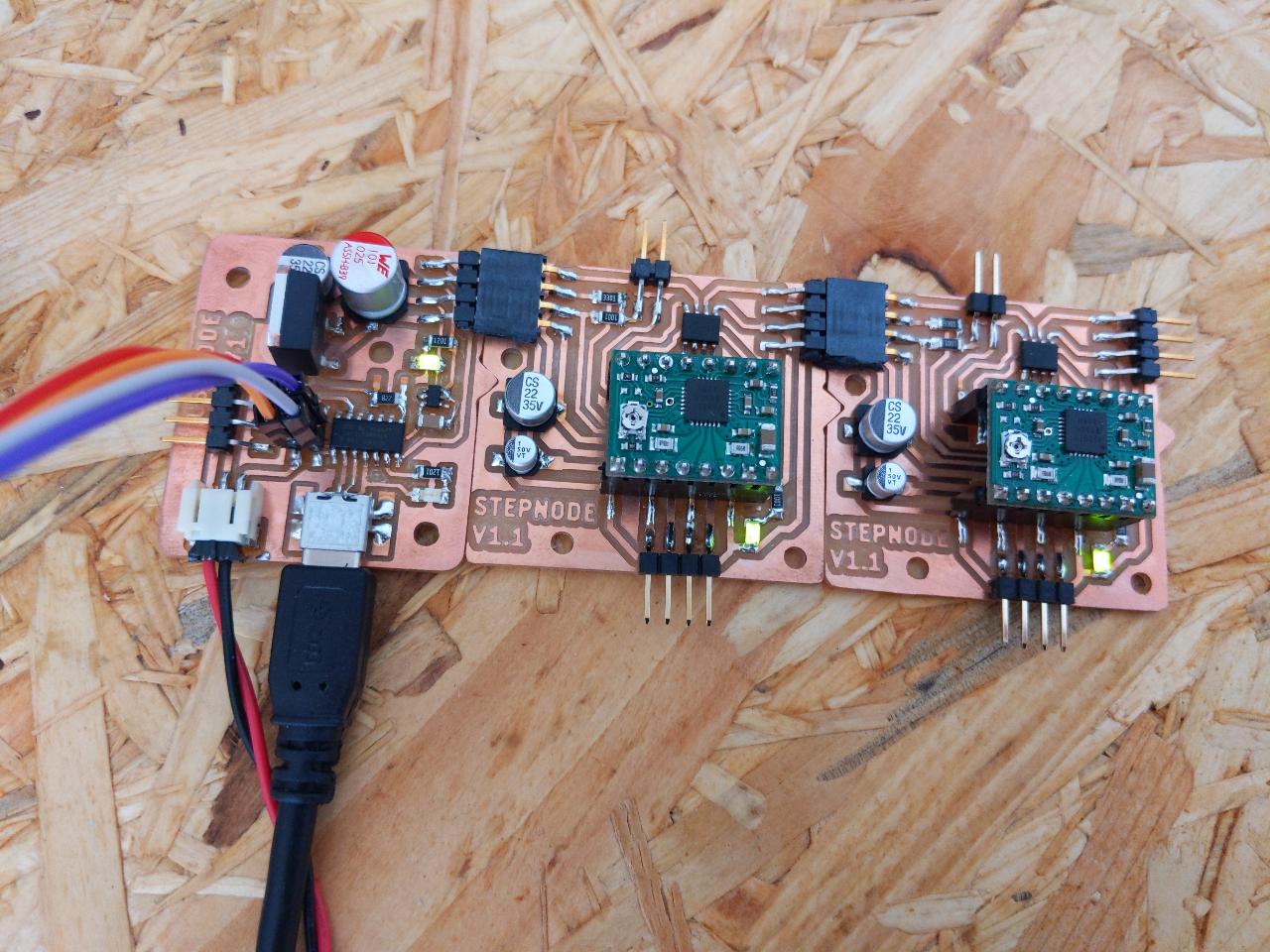
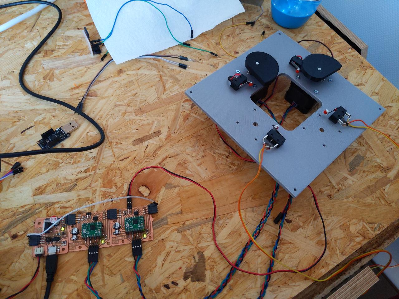
By streaming the same byte repeatedly, I tested the motor rotation successfully!
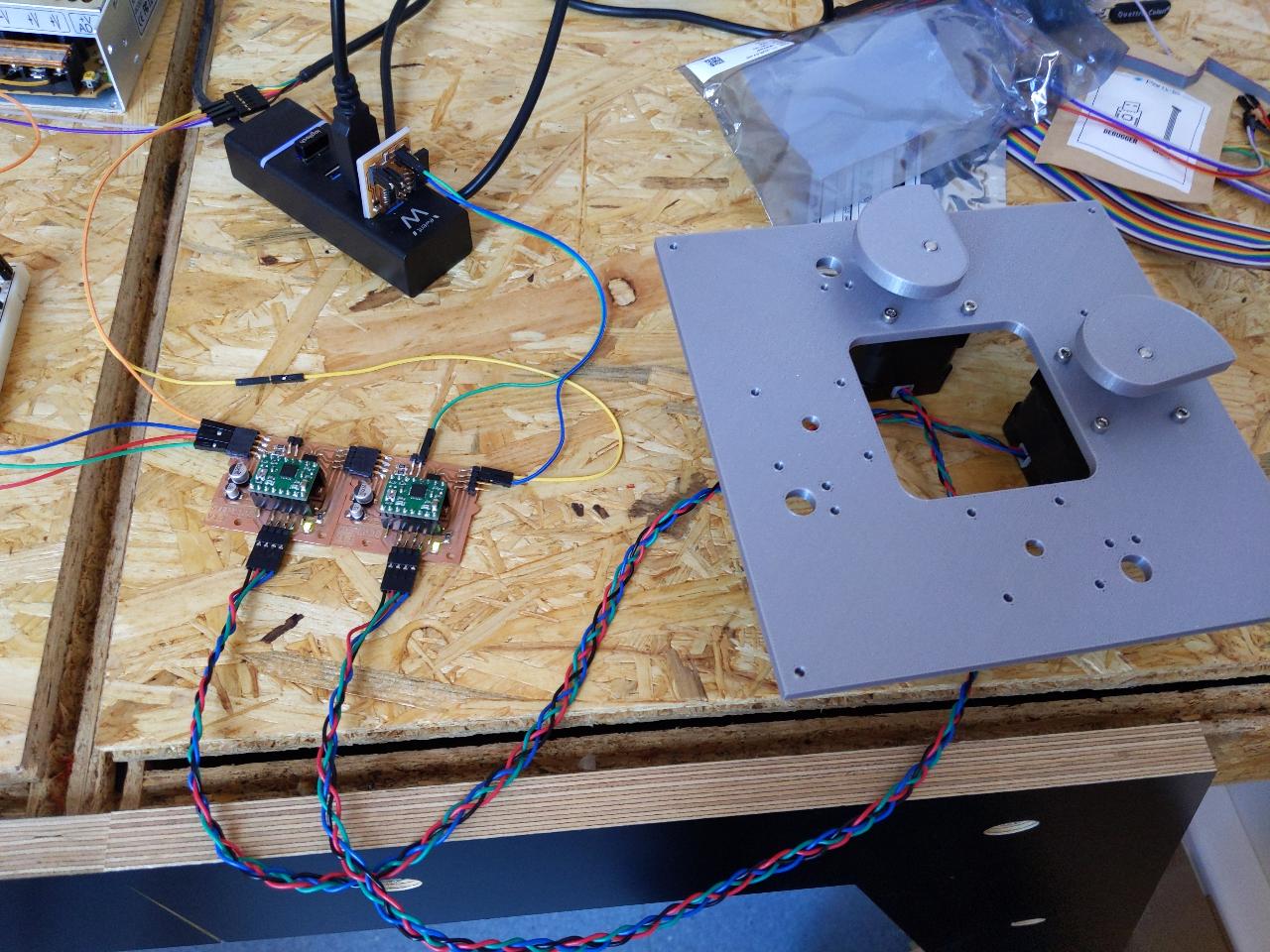
Connecting the next node and programming both, I checked that the forwarding concept worked fine. At this stage, some mechanical parts were finished too, so we started assembling.
Here is a video of it:
Interfacing with the PC
The missing board should have the following features:
- 12V input connector
- uA7805C 5V regulator, large enough to power up all other nodes.
- USB connector with a UART-USB able chip.
I picked the SAMD11C14 as the microcontroller, as I already had experience with it. Here is the schematic:

And here is the board:
Note that this node can only be connected on the left of other nodes, so it’s always first. The 4-pin connector on the left is meant for feeding back the UART line with a flexible cable. All other paads are present but not connected.
I milled it on home CNC, which is a modified 3018 CNC.
Stuffing this board was extremely challenging, mostly due to the small pins of the USB connector.
To program this node, I use a JTAG programmer on the 4 pin connector next to the SAMD11C. There is nothing fancy going on in the firmware, it’s simply a USB to UART adapter so I use the same firmware I showed here.

This node connects on the left of the other boards properly, and provides the 12V and 5V as intended.
Finally, a small cable provides the feedback on the UART line.
Assembly
When the full electronics was shown to be working, the main stage was ready for assembly:
I prepared a small 2.1mm to JST adapter for the 12V input.

Robin prepared a nice housing to protect the elctronics. The placement of the holes was based on my EAGLE design files.
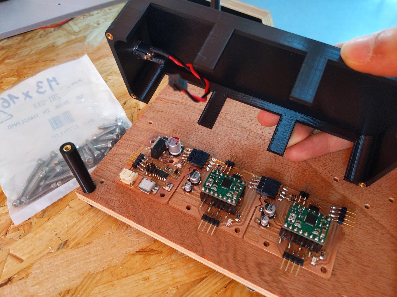
Some 3mm screws with a plastic ring are used to mount the parts.

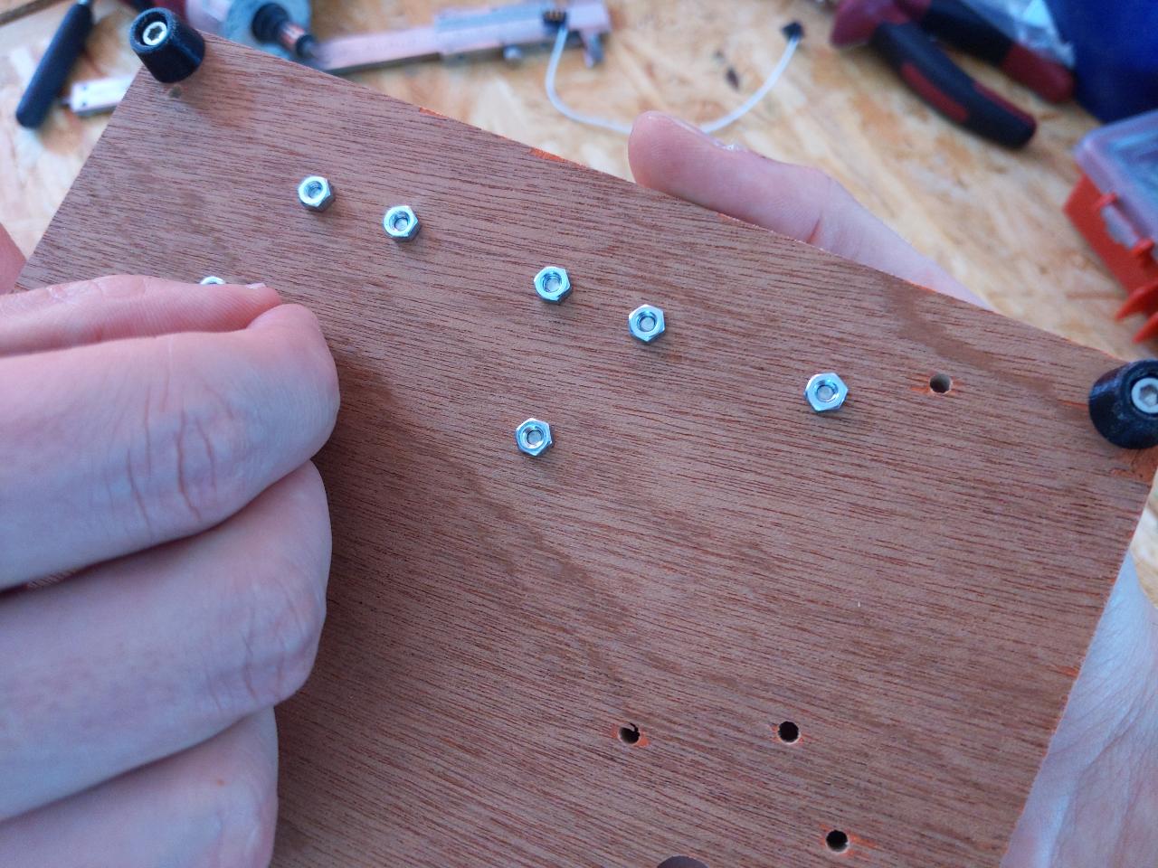
The other side is secured with 3mm nuts.
The loopback cable is designed to fit in the box with strict tolerance on the sides.
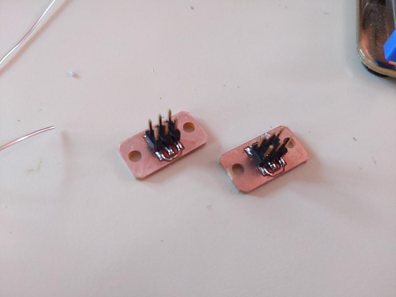
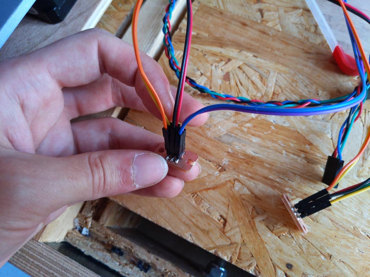
Because the endstops are normally closed and we have both min and max endstops, I quickly designed a pcb to put them in series. Connected this way, any of the two endstops triggers the pin. Knowing the motion direction, you can deduce wether the max or min was hit.
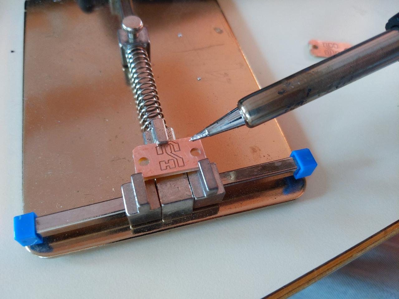
Simple 3x2 connectors do the job.
The connectors are secured in the corner of the main plate.
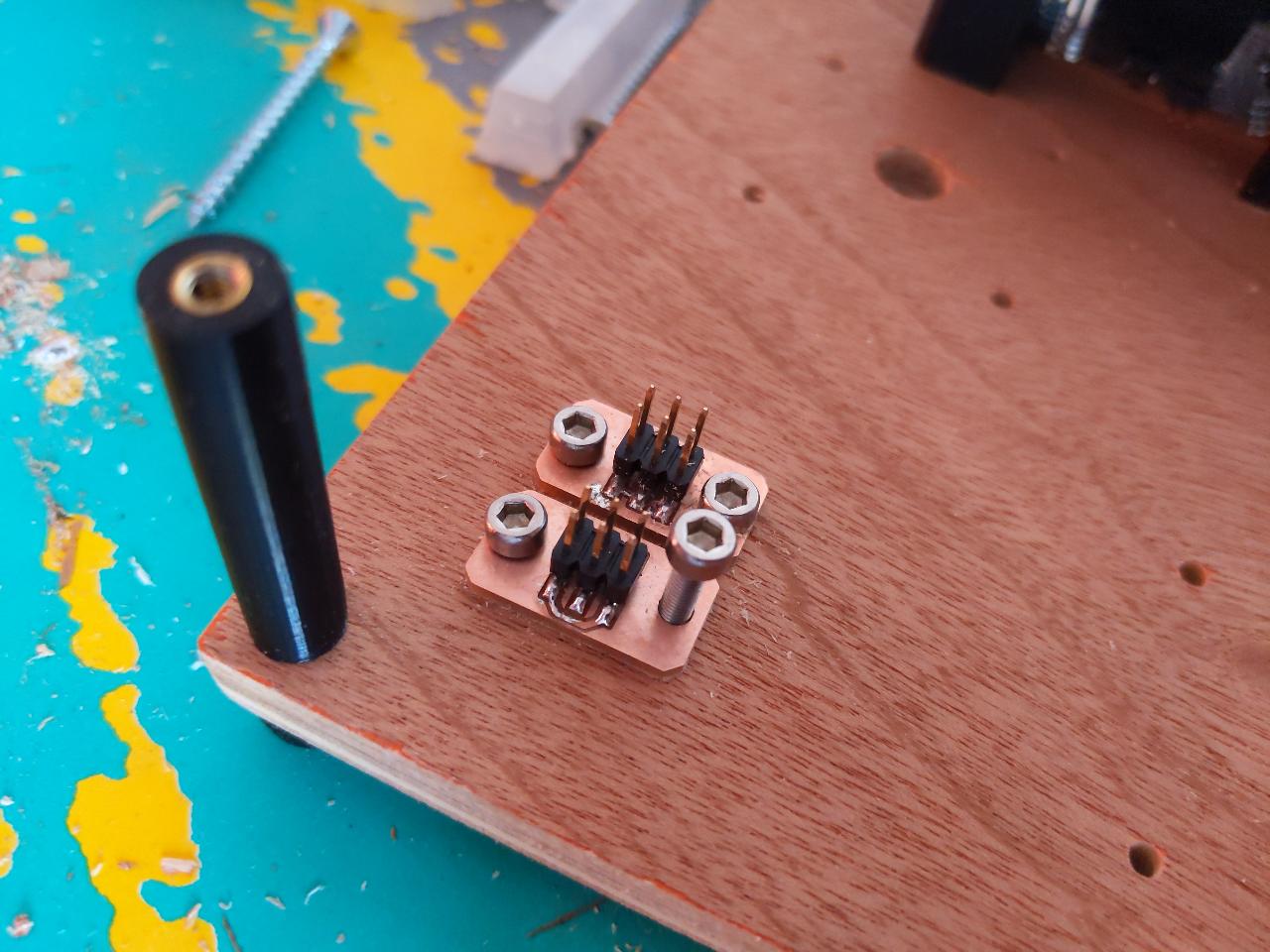
The blue/purple cable on the right here is what goes to the PCB, and both endstops are connected to the other pins.
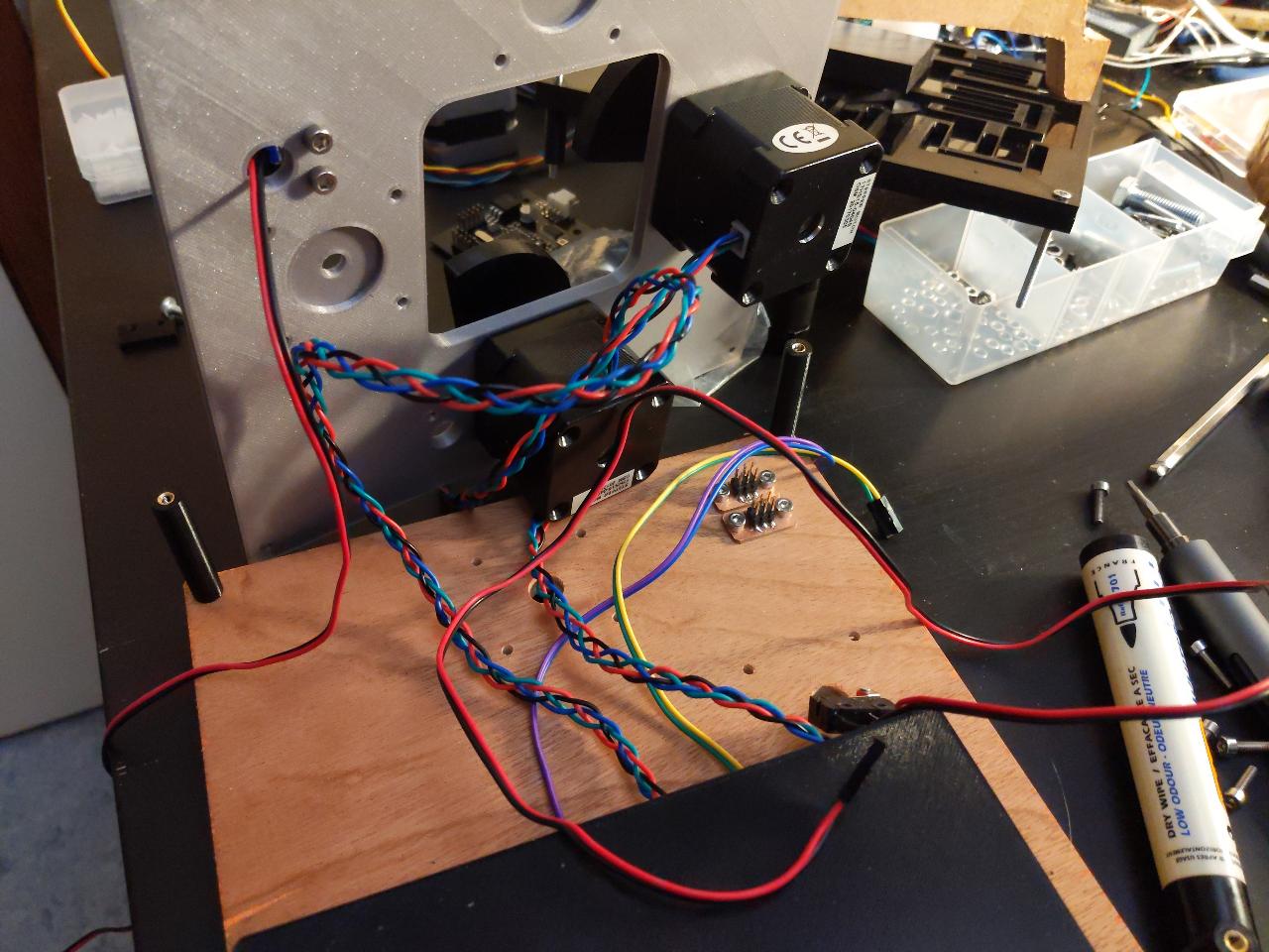
With this being solved, we can add the motor stage.

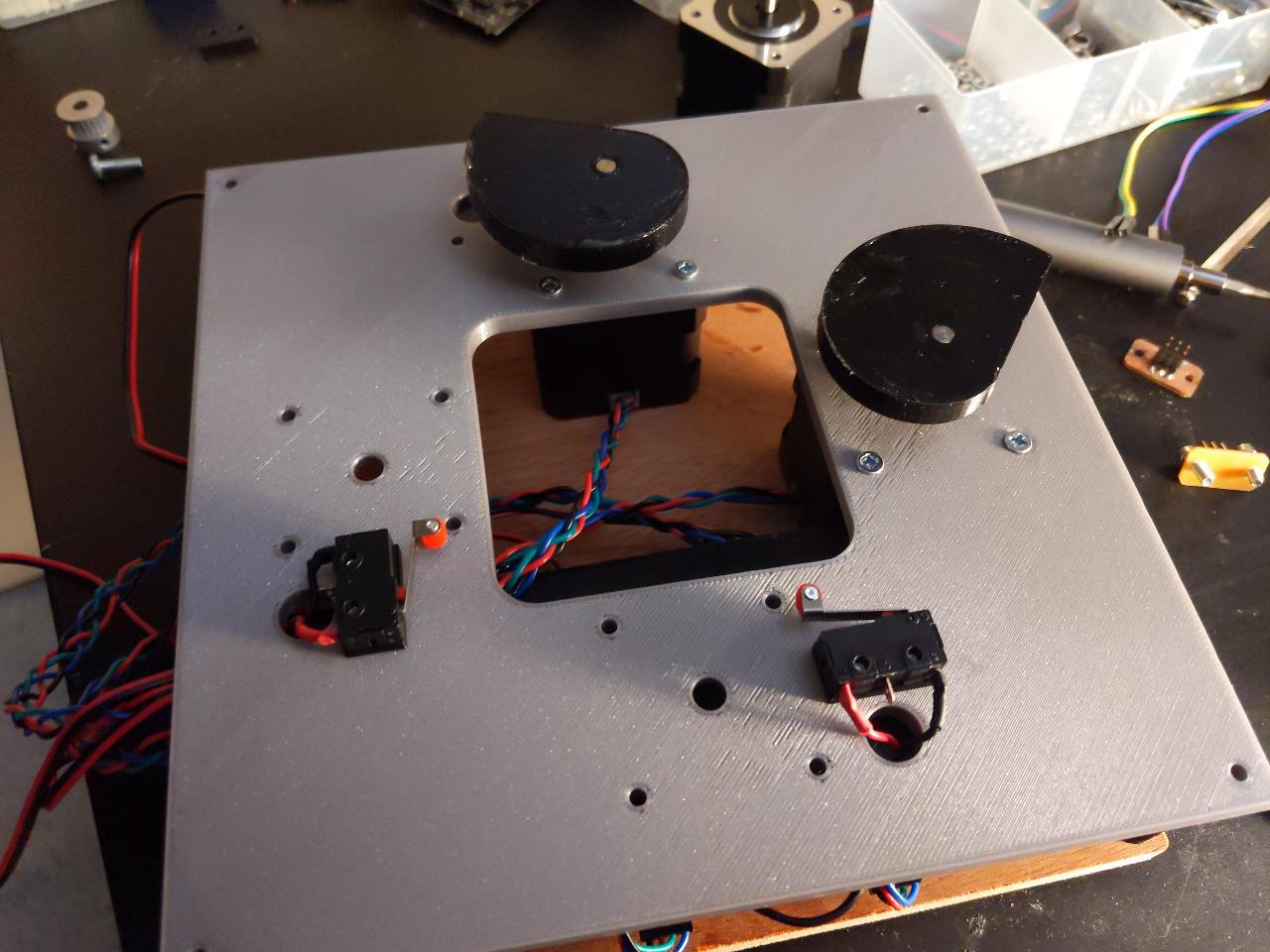
And finally, the flexible XY stage sits on top.

The final machine is about 18cm wide.

After some tests, I ended up simplifying the mechanics a bit. I removed the springload system, as it was too strong to compress for the motors. As a drawback, we can only use one quarter of the working area, as there is no force feedback on the other parts. This results in a tiny working area of 7.2 x 7.2mm.
Due to this, two of the endstops were not reachable so I promptly removed them.
With fewer endstops, the cable management is easier.
Software
Controlling stepnodes in realtime from the computer is not an easy task, so I will only show a proof of concept Python script. It is not ideal, as there is no guarantee on the timing in my current version. However, it works fine for drawing simple curves and lines, which is enough for the purpose of this project.
In a nutshell, the following NodeController class can communicate with up to 4 nodes, sending steps with a function call to step().
class NodeController:
    lookup_cmd = {-1: 0b01,
                  0: 0b00,
                  1: 0b10}

    def __init__(self, port, steps_per_unit, steps_max):
        n = len(steps_per_unit)
        if n > 4:
            raise ValueError("Max 4 nodes are supported for now.")
        self.n = n
        self.vec_pos = np.zeros((n,), np.float64)
        self.vec_steps = np.zeros((n,), np.int32)
        self.vec_enabled = np.zeros((n,), np.bool)
        self.vec_endstop = np.zeros((n,), np.bool)
        self.steps_per_unit = np.array(steps_per_unit, np.float64)
        self.steps_max = np.array(steps_max, np.int32)
        self.port = port
        self.serial = None
        self.recv = 0

    def step(self, step_vals):
        # make a unit step in each axis, choice in [+1,0,-1]
        msg = 0
        for i, v in enumerate(step_vals):
            msg |= self.lookup_cmd[v] << (i*2)
        self.vec_steps += step_vals
        self.serial.write([msg])
        self.serial.flush()
        # naive way of doing it: take only 1 byte
        self.recv = self.serial.read()[0]
        self.refresh_status()
Repeated calls to this step() function at the desired rate can produce any motion sequence on the motors. You will find the full code at the end of this page. As an example, here is how this class implements moving from the current point to a target point:
def goto(self, pos, feedrate):
        # pos in [units], feedrate in [units/s]
        delta = np.array(pos) - self.vec_pos
        dist = np.linalg.norm(delta)
        duration = dist/feedrate
        t = datetime.datetime.now()
        dt = 0

        pos_init = self.vec_pos.copy()
        while dt < duration:
            dt = (datetime.datetime.now() - t).total_seconds()
            pos_new = pos_init + delta * dt/duration
            self.update_pos(pos_new)
Results
Here is a video of a homing sequence followed by a circular motion:
From the side, you can see that the motor is correctlyt pushing the XY stage:
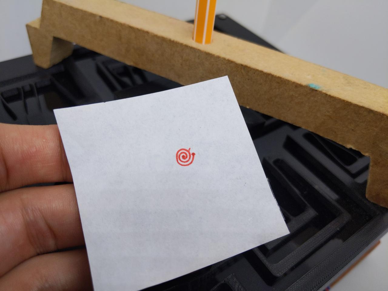
To see what kind of accuracy the machine can reach, I needed to mount a pen on top of the XY stage, so I quickly cut some MDF wooden arc.

I add a red pen and stick a paper sheet on the stage.
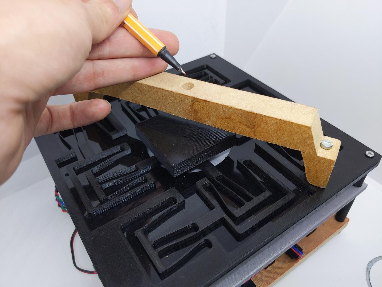
Here is a drawing of a very small spiral:
The spiral is not perfect on all sides, but the center shows some high accuracy in the motion.