13. Interface and Application Programming
This week is dedicated to exploring programming languages and graphical interfaces. I will use Python, as it is natively multiplatform and very diverse in its use.
We present other programming languages and frameworks in our group assignment.
I present two applications:
- A universal Gcode sender for a moving rail equipped with a camera.
- An OpenGL version of prof. Gershenfeld’s frep.py script. The result is shown to be much faster when rendering large resolution images.
Moving rail controller
For my final project, I need to control a moving camera system, and shoot it at given times. I can simulate this principle using a very basic moving rail supporting Gcode instructions. Detailing how to build this rail is outside the scope of this week’s assignment, but I will document it separately.
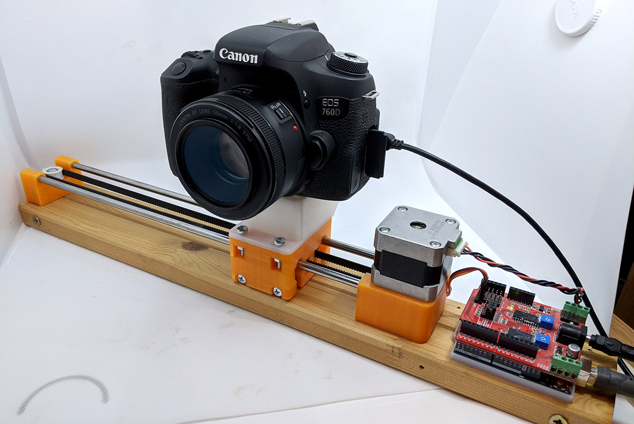
This rail supports the following Gcode commands:
M17: turn on motorsM18: turn off motorsG28: return to home positionG1 X(x_pos) [F(x_rate)]: move at a given position (mm), with optional feedrate (mm/s)
It would be convenient to have a graphical interface that can simultaneously send Gcode commands to control the rail, and trigger the camera with a separate cable. For this purpose, I build a graphical interface using PyQt5, which is a Python binding of the Qt framework. It allows to create responsive applications, where all user actions can be connected to an elegant system of callbacks. Moreover, QtDesigner is included, letting me design my application graphically.
QtDesigner
Although the whole application could be created through code, I found it helpful to visualize the application when building it. I started with a basic window, and tried to put the items in a good layout.
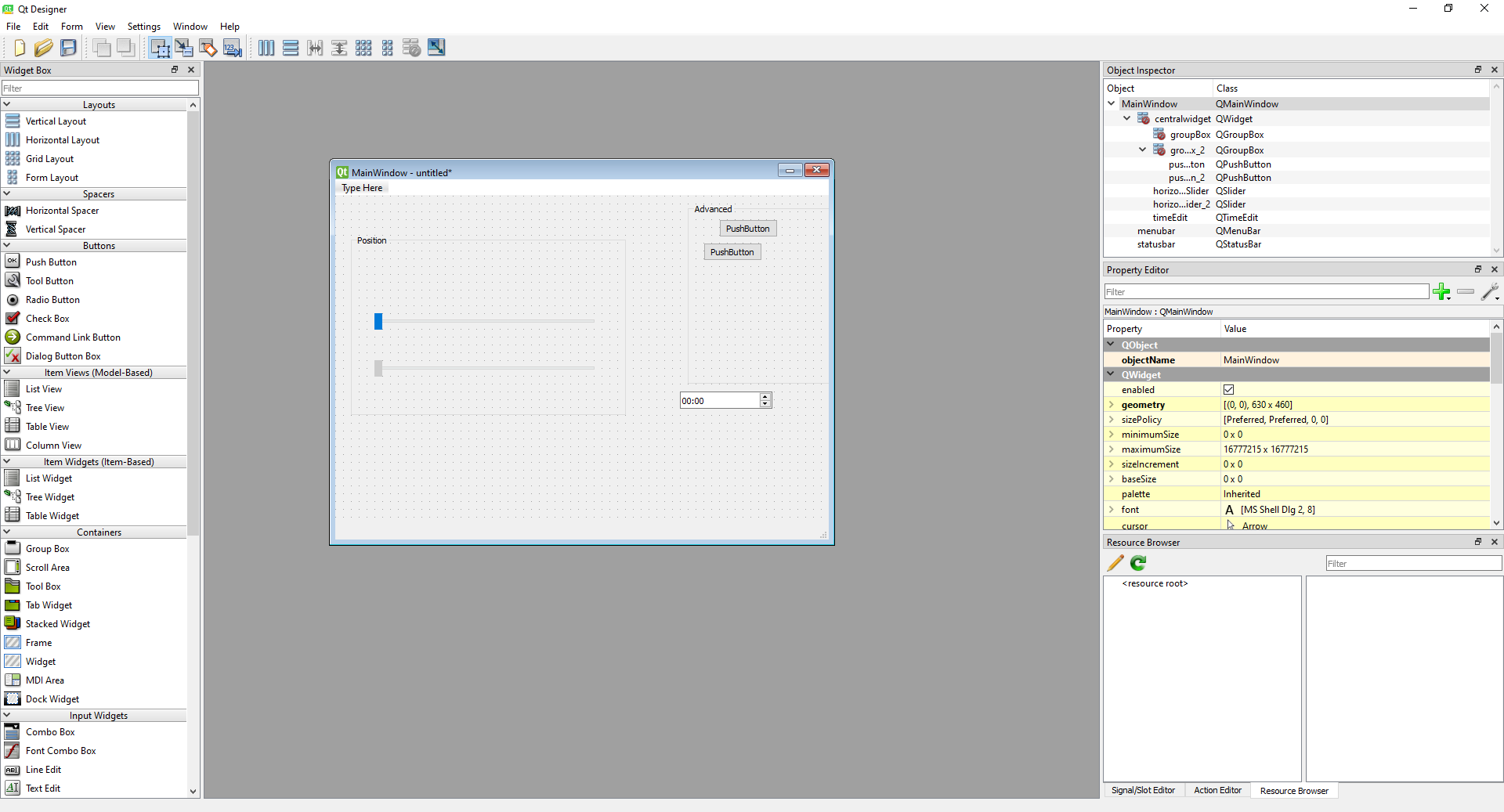
The layour mechanic is quite important in Qt: it allows container items to spacially organise their children objects in an intuitive way. I used several layout types in this project:
vertical layout: children take full width, and stack up vertically.horizontal layout: children take full height, and are next to each other.grid layout: arbitrary number of columns/rows can be created, and a child can cover several cells if needed.
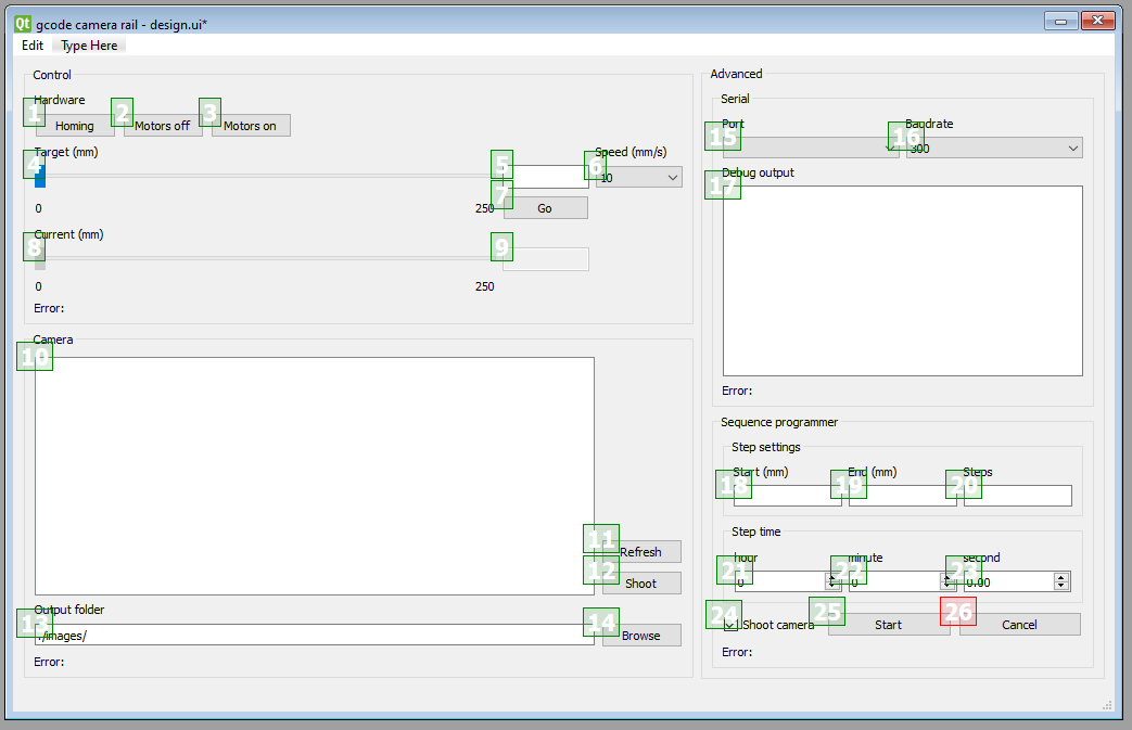
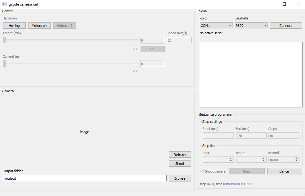
In my final design, I have sperated buttons in 4 main categories:
Control: contains a slider and buttons to directly move the rail, and displays its current position.Serial: lets the user connect to a given serial port with the specified baudrate, and incldes a small terminal to visualize the incoming/outgoing messages.Camera: lets the user shoot the camera and specify in which folder to transfer the image. It then displays the latest file in that folder.Sequence: allows to program motion sequences from the current position to a final position, with a number of steps. The duration of each step is specified in a HH:MM:ss format.
An important detail is that each of these groups has its own text label for displaying errors or messages.

Once I am happy with the layout, I can save the result to a .ui that can easily be loaded from PyQt. As a final touch, I can choose the order in which items are selected when pressing tab on the keyboard with the Edit tab order mode.
With the .ui file created, it’s time to load it in the code and connect each button to a specific action. This is the right time to think about dependecies and the software architecture.
Dependencies
This project requires the following:
Python 3.7+PyQt5, can be installed withpip install pyqt5pyserial, can be installed withpip install pyserial
Software architecture
This software will be built with Object Oriented programming in mind, and communication with the graphical interface will be netirely based on callback functions. I found it natural to create three main classes:
MainWindow: a custom child class ofQtWidgets.QMainWindow, it handles all items in the GUI and their callback.MovingRailServer: connects to the serial port of the rail, and sends the appropriate Gcode commands when theMainWindowrequests so.CameraServer: sends camera shooting commands when needed in a child subprocess withPopen(). This is non-blocking, and allows theMainWindowto frequently poll to checkthe progress of the shooting.
Subdividing each function in a separate class is important to improve code readability and ease of maintenance. For instance, if I decide to change the Gcode commands entirely, I can modify CameraServer without changing its API so that the MainWindow can retain the same function calls to it.
I like to program in PyCharm Community edition. I sometimes use Atom for small edits, but PyCharm is more powerful when building Python code specifically, as it includes an entire Python interpreter engine. It infers the type of all variables to suggest autocompletion of methods and attributes.
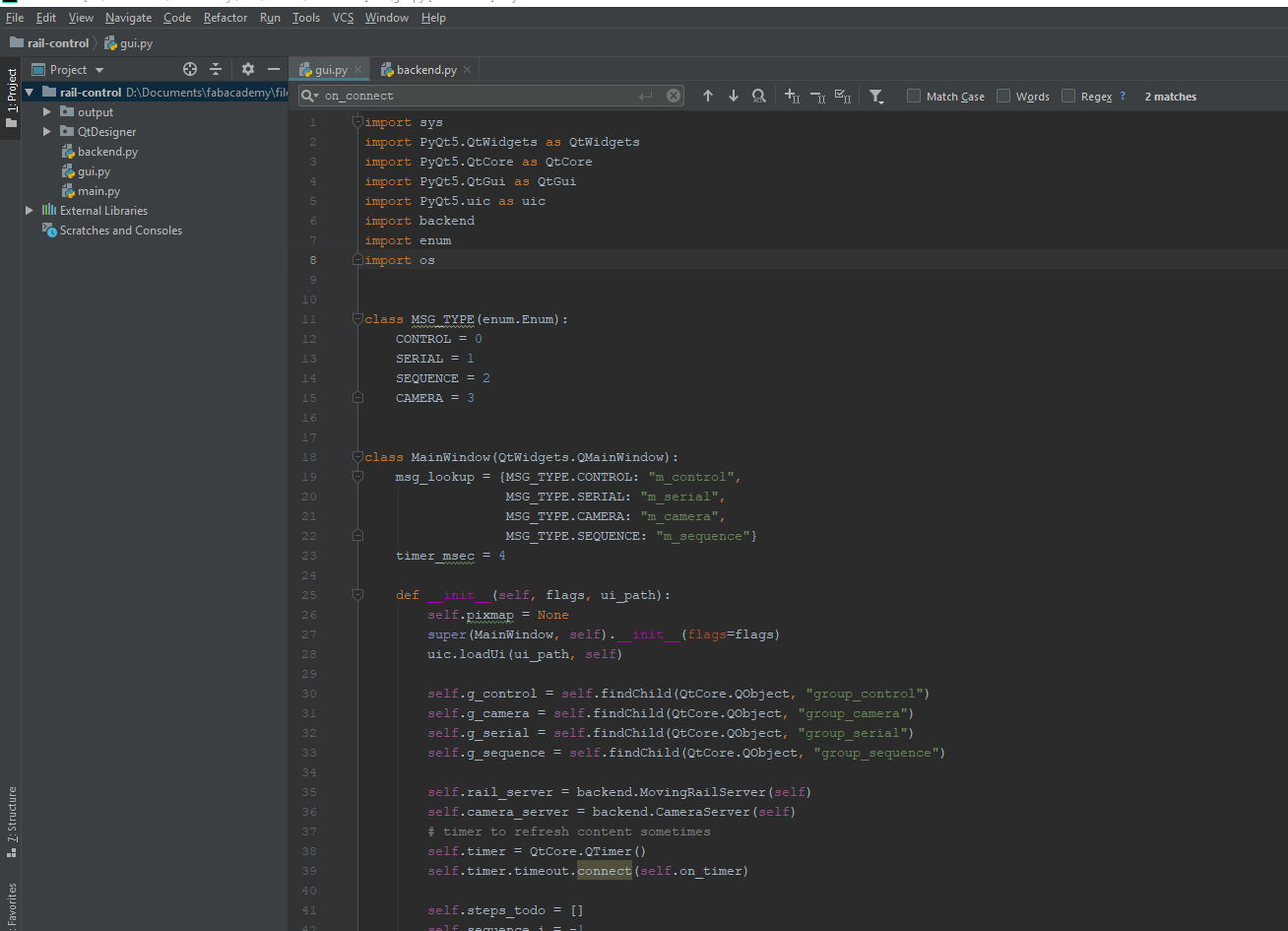
In the constructor of the MainWindow I do the following:
class MainWindow(QtWidgets.QMainWindow):
    def __init__(self, flags, ui_path):
        super(MainWindow, self).__init__(flags=flags)
        uic.loadUi(ui_path, self)
        ...
The super().__init__ calls the constructor of the parent class. Then I directly load .ui file I created with QtDesigner with the command loadUi(). To connect each button to a functionality, I need to connect a callback to the correct “signal” of each button. A signal is a powerful mechanic introudced by Qt to interconnect items and automate actions. In my application, I will only connect signals to callback functions of MainWindow. For instance, conisder the Shoot button in the Camera section. The following code sets up the callback:
b = self.findChild(QtWidgets.QPushButton, "b_shoot")
b.clicked.connect(self.on_shoot)
Where self.on_shoot is a method of MainWindow defined as:
def on_shoot(self):
    self.camera_server.shoot()
    self.is_shooting = True
Notice how a reference to a function can be made by providing only its name, without parentheses. Thanks to this, Qt has a reference to on_shoot and will call it when the button is clicked.
It is important to enable/disable buttons depending on the availability of their functionality. This is achieved through the setEnabled() method common to all QtWidget objects. When I start the application, There is no active serial, so I disabled most buttons to indicate it clearly:
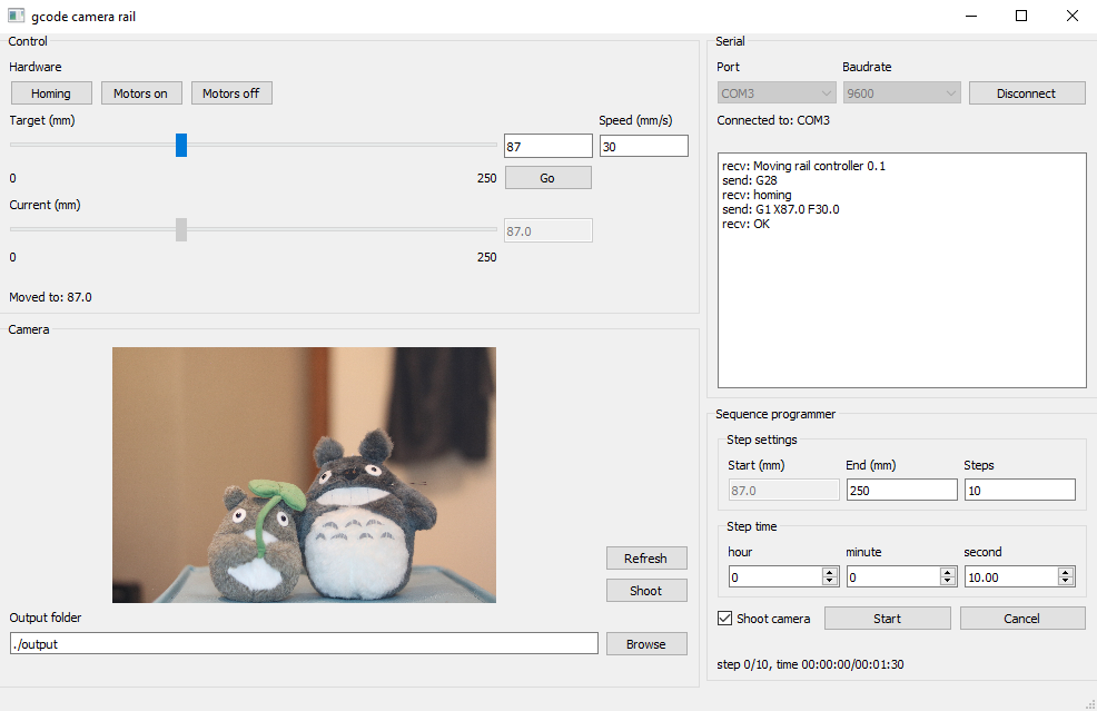
But once a serial connection is made, all buttons are enabled. Some items are always disabled though, to indicate that no action is needed. This is the case for the current position slider and value.
When clicking on the serial connect button, the following function is called in the MovingRailServer:
def connect(self, device, baudrate, timeout=1):
    try:
        self.port = serial.Serial(device, baudrate, timeout=timeout)
        self.port.send_break()
    except serial.SerialException as e:
        self.window.display_msg("Error: {}".format(e), gui.MSG_TYPE.SERIAL)
        return False
    return True
Notice how an error will be displayed in case of failure. As said previously, messages are displayed in the right location in the app, and this is performed by the following method of MainWindow:
class MSG_TYPE(enum.Enum):
    CONTROL = 0
    SERIAL = 1
    SEQUENCE = 2
    CAMERA = 3

class MainWindow(QtWidgets.QMainWindow):
    msg_lookup = {MSG_TYPE.CONTROL: "m_control",
                  MSG_TYPE.SERIAL: "m_serial",
                  MSG_TYPE.CAMERA: "m_camera",
                  MSG_TYPE.SEQUENCE: "m_sequence"}

    ...

    def display_msg(self, txt, msg_type):
        m_name = self.msg_lookup[msg_type]
        m = self.findChild(QtWidgets.QLabel, m_name)
        m.setText(txt)
The msg_lookup is a static attribute of MainWindow, and it maps a given message type to the name of a widget in the GUI.
Here is a video of the connection and simple motion:
Camera rail - connect from pythonzen on Vimeo.
In the following video, I trigger the camera which automatically downloads and refreshes the picture:
Camera rail - shoot from pythonzen on Vimeo.
The camera is triggered thanks to a suprocess call of CameraControlCmd.exe from digiCamControl. Unfortunately, this is a windows-only software, but it can be replaced with any other command-mine tool for shooting the camera. This currently requires to modify the code of CameraServer.
Finally, we can try out the sequence program (I disabled the camera trigger to make the video shorter):
Camera rail - sequence from pythonzen on Vimeo.
You will find the source code for this project at the end of this page.
Future improvements
There is currently no dynamic settings, which means the min/max positions of the rail and the command to trigger the camera are currently hardcoded. In the future, I should include a settings window dialog, or at least a configuration file to replace some options with different values.
FInally, the current software is currently not very reobust to wrong user inputs, there should be more sanity check to prevent runtime errors.
frep_gpu.py, an OpenGL port of frep.py
In this project, I want to mak a proof-of-concept OpenGL rendering of the frep.py script proposed by prof. Gershenfeld as part of his pcb.pysystem presented here. Currently, the rendering of the logic function describing the PCB is performed using numpy, and I suspect that a great speedup can be obtained if using the power of the GPU. Computing the value of each pixel can be done independently, so a massively parallel computing architecture is perfect for this job.

Dependencies
This project requires the following:
Python 3.7+PyOpenGL, can be installed withpip install PyOpenGL PyOpenGL_acceleratePIL, can be installed withpip install Pillownumpy, can be installed withpip install numpyGLUT, installed separately.
OpenGL shaders
OpenGL is the most popular language used to interface between the computer and the GPU. It includes all functions to send data and code to the GPU’s memory. A binary program on the GPU must first be compiled, and this is done at runtime with GLSL shaders. Here we use two types of shaders:
- Vertex shader: specifies the position of each vertex to be displayed.
- Fragment shader: computes the color of each “fragment”, in this case a fragment is simply a pixel of the image we want to compute.
In our case, we want to compute an image covering the whole screen, so we use the following trick to cover the screen entirely:
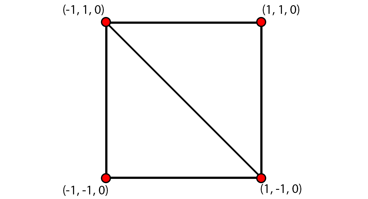
Those two triangles cover all 4 corners of the OpenGL screen space. The main idea of this software is to compute a given logical function for all pixels in the specified area. The vertex shader is very basic:
#version 420

uniform vec2 x_lims;
uniform vec2 y_lims;
uniform float z;

layout (location = 0) in vec3 pos;
out vec3 v_pos;

float map(float value, float min1, float max1, float min2, float max2) {
    return min2 + (value - min1) * (max2 - min2) / (max1 - min1);
}

void main() {
    gl_Position = vec4(pos, 1.0);
    float x, y;

    x = map(pos.x, -1, 1, x_lims.s, x_lims.t);
    y = map(pos.y, -1, 1, y_lims.s, y_lims.t);
    v_pos = vec3(x, y, z);
}
The gl_Position is the position of the vertex in screen space, and the v_pos is an output that will be used by the fragment shader. While gl_Position is sceen space coordinates, v_pos is expressed in world units. Here is the fragment shader:
#version 420
uniform vec3 color;
uniform float alpha;

in vec3 v_pos;
out vec4 f_color;

void main() {
    float X, Y, Z;
    X = v_pos.x;
    Y = v_pos.y;
    Z = v_pos.z;

    bool c = [F_LOGIC];

    f_color = vec4(color, float(c)*alpha);
}
As you can see, there is a placeholder [F_LOGIC]. This needs to be replaced by the logical function evaluated as a function of X, Y and Z. When the function is true, the pixel is written with the specified color and transparency (alpha), otherwise the output is fully transparent and will not affect the screen.
Architecture
The output of pcb.py is a .json file where the function is encoded as a string. To make this output compatible with GLSL shaders, I needed to make several important changes.
- No color in the function: originally, the RGB color was encoded directly in the 24 bits of the logical function. To speed up computation, I decided to use booleans only, so I had to remove colors from the function.
- several functions: there is now a list of functions in the
.json, each having its own color and alpha. A layer can also be disabled. - color byte order: RGB bytes are now left to right instead of right to left, so that hexadecimal color codes can be used.
- change of built-lin names: True/False is now true/false without capital, and math.cos/math.sin is simply cos/sin.
- logical operators: logic inversion is now
!instead of~, and the operators&and|are now&&and||respectively. - float numbers only: numerical values always have a decimal part to avoid mixing floats and ints.
Here is an example of .json output drawing a red dot and a white rectangle:
{
"functions": [{"f": "(X*X)+(Y*Y) <= 1.0", "color": 16711680, "alpha": 1.0, "active": true},
              {"f": "(X <= 0) && (X >=-1.5) && (Y >= -1.5) && (Y <= 0)", "color": 16777215, "alpha": 0.7, "active": true}],
"layers": [0],
"xmin": -2,
"xmax":  2,
"ymin": -2,
"ymax":  2,
"mm_per_unit": 25.4,
"type": "RGB"
}
This file produces the following result (note the transparency of the rectangle):
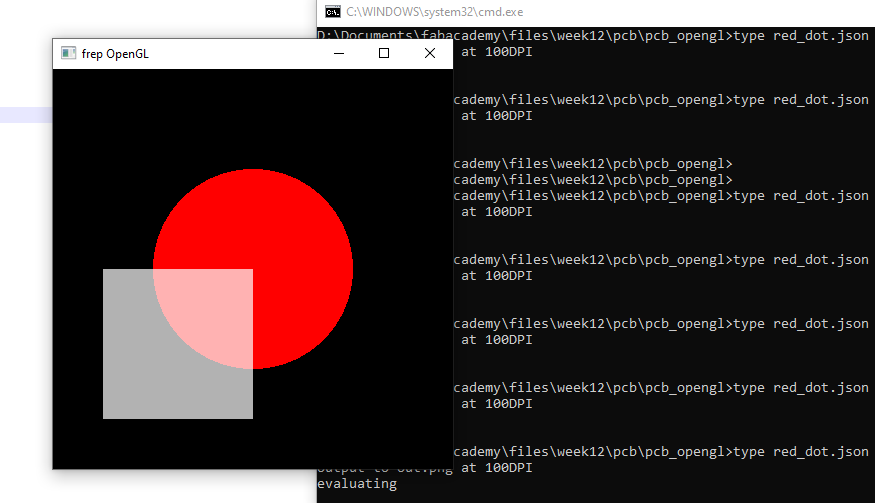
Each z is rendered in the order sepcified in layers. Each logical function is turned into a GLSL shader, and rendered on top of a black canvas one after the other:
for z in self.z_list:
    for i in range(len(self.shader_list)):
        prog = self.shader_list[i]
        f = self.functions_list[i]
        if not f["active"]:
            continue
        color = f["color"]
        rgb = (((color & 0xFF0000) >> 16)/255.0, ((color & 0x00FF00) >> 8)/255.0, (color & 0x0000FF)/255.0)
        alpha = f["alpha"]
        ...
        # rendering
        glDrawArrays(GL_TRIANGLE_STRIP, 0, 4)
The uniform parameters are passed to the shader with the following code snippet:
glUseProgram(prog)
loc_color = glGetUniformLocation(prog, "color")
loc_alpha = glGetUniformLocation(prog, "alpha")
loc_x_lims = glGetUniformLocation(prog, "x_lims")
loc_y_lims = glGetUniformLocation(prog, "y_lims")
loc_z = glGetUniformLocation(prog, "z")
glUniform3f(loc_color, *rgb)
glUniform1f(loc_alpha, alpha)
glUniform2f(loc_x_lims, *self.x_lims)
glUniform2f(loc_y_lims, *self.y_lims)
glUniform1f(loc_z, z)
To the best of my knowledge, it is not easy to enable OpenGL without having an active context, requiring an open window. Because of that, this application will show the result for a very short duration (min. 1 frame) then close and save the image to a file.
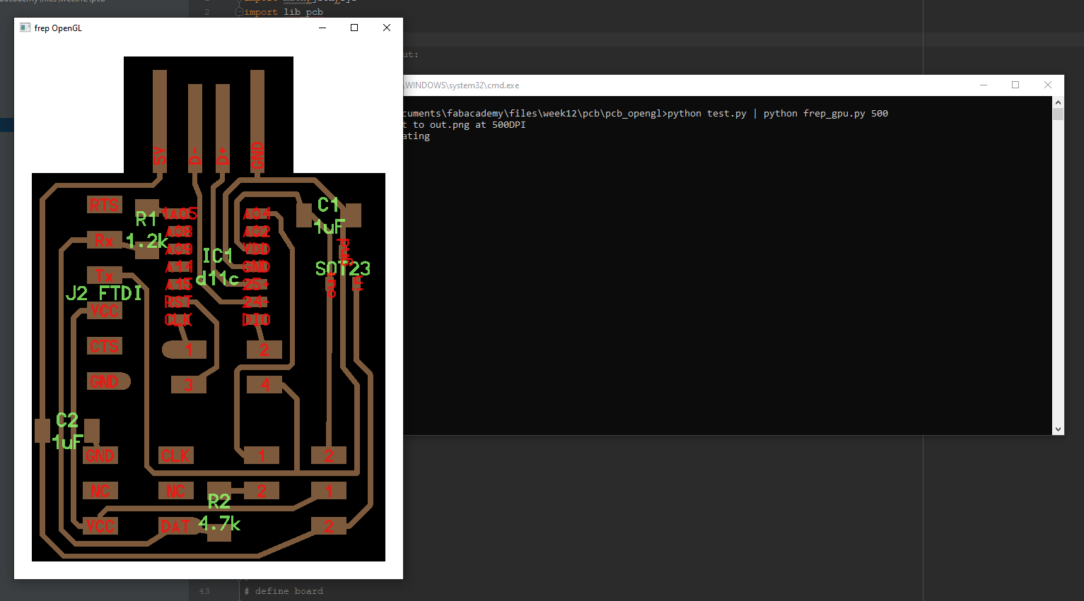
Speed comparison
To compare with the original frep.py running on CPU, I decided to measure the total duration of a PCB rendering (including the duration of pcb.py). For this purpose, I use the following PCB, which I designed for the Electronics design week:
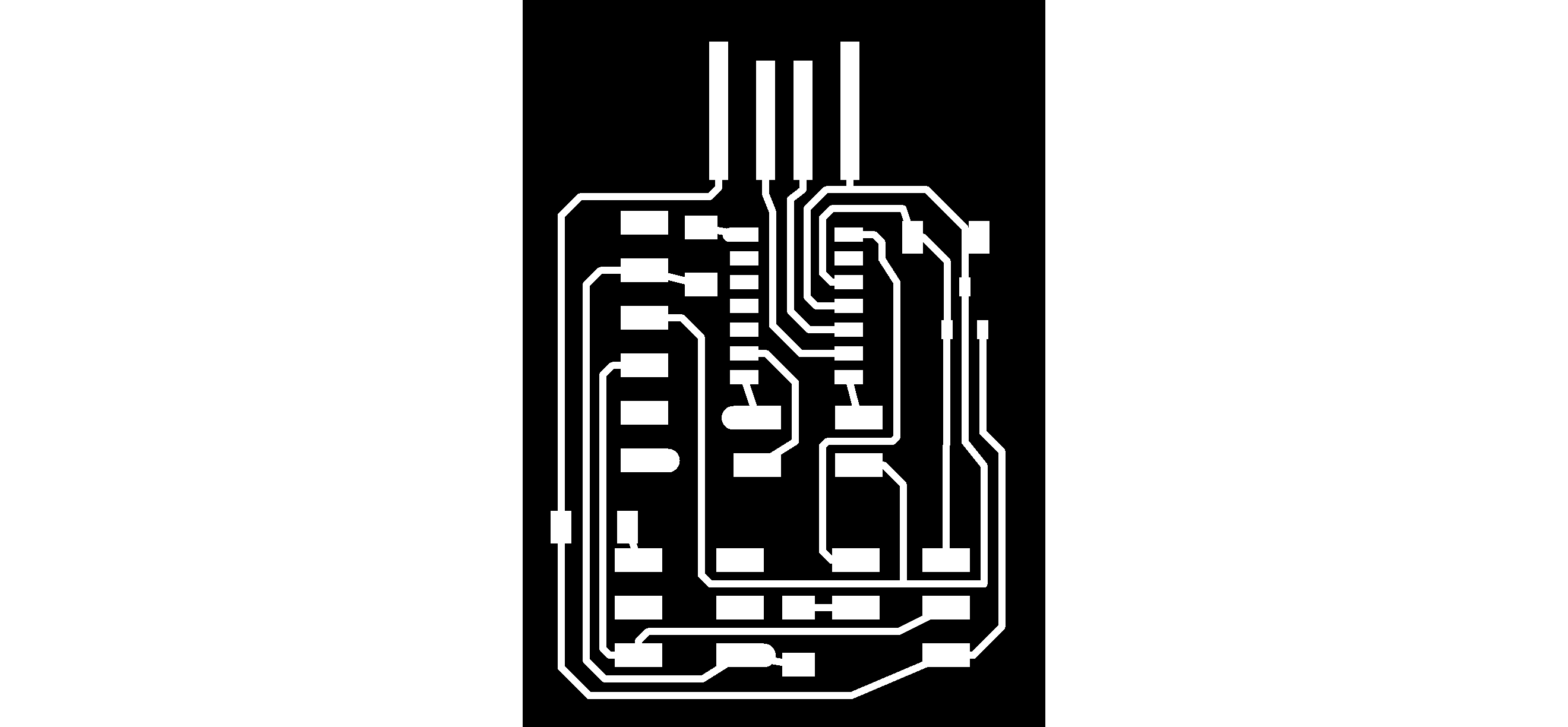
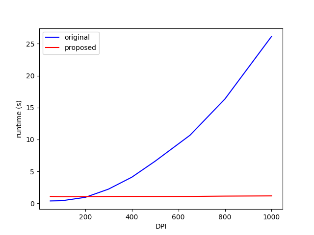
Only the top traces are enabled, and the DPI varies from 50 to 1000, and the test is run on a PC with the following specs:
- CPU: Intel Core i5-3570K @ 3.4GHz
- GPU: Nvidia GTX 1070
- RAM: 16 Gb DDR3
As excepted, the runtime is near constant for our OpenGL code, showing that the GPU’s full computing capacity is not reached. However, there is a significant overhead when creating the OpenGL context, making this software slightly slower for very low DPI.
Future improvements
This software is in a very early stage. To overcome the overhead problem, it would be interesting to keep the viewer opened, and update the shaders whenever requested by the user. This requires some form of communication between pcb.py and frep_gpu.py.
Moreover, I need to update frep.py to support the new .json format. I first need to make sure the proposed format contains all necessary features to become a standard.