17. Wildcard week : sand drawings
This week is different from the others: this time, I should pick the topic myself. The idea is to explore a process that was not covered during another assignment, but lines up with the digital fabrication theme of the fabacademy.
For my topic, I propose to make drawings in the sand using a CNC machine. Placing a sandbox onto the build plate of a CNC is relatively easy, so the additional objectives are:
- Design and test a multi-purpose toolhead for drawing in sand in several ways.
- Produce original gcode using a homemade script.
- Find a way to film the process with a camera.
Modifying the CNC
The first step is to modify my CNC to add a sandbox on the build plate. I start by cutting some 12mm plywood.
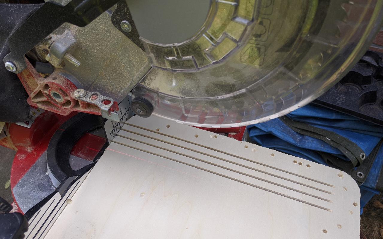
I obtain the 4 sides of my sandbox. The long sides are 27mm long, and the short side 18mm.
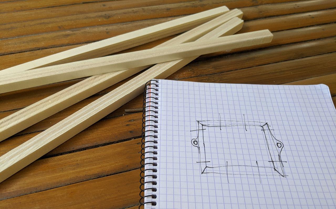
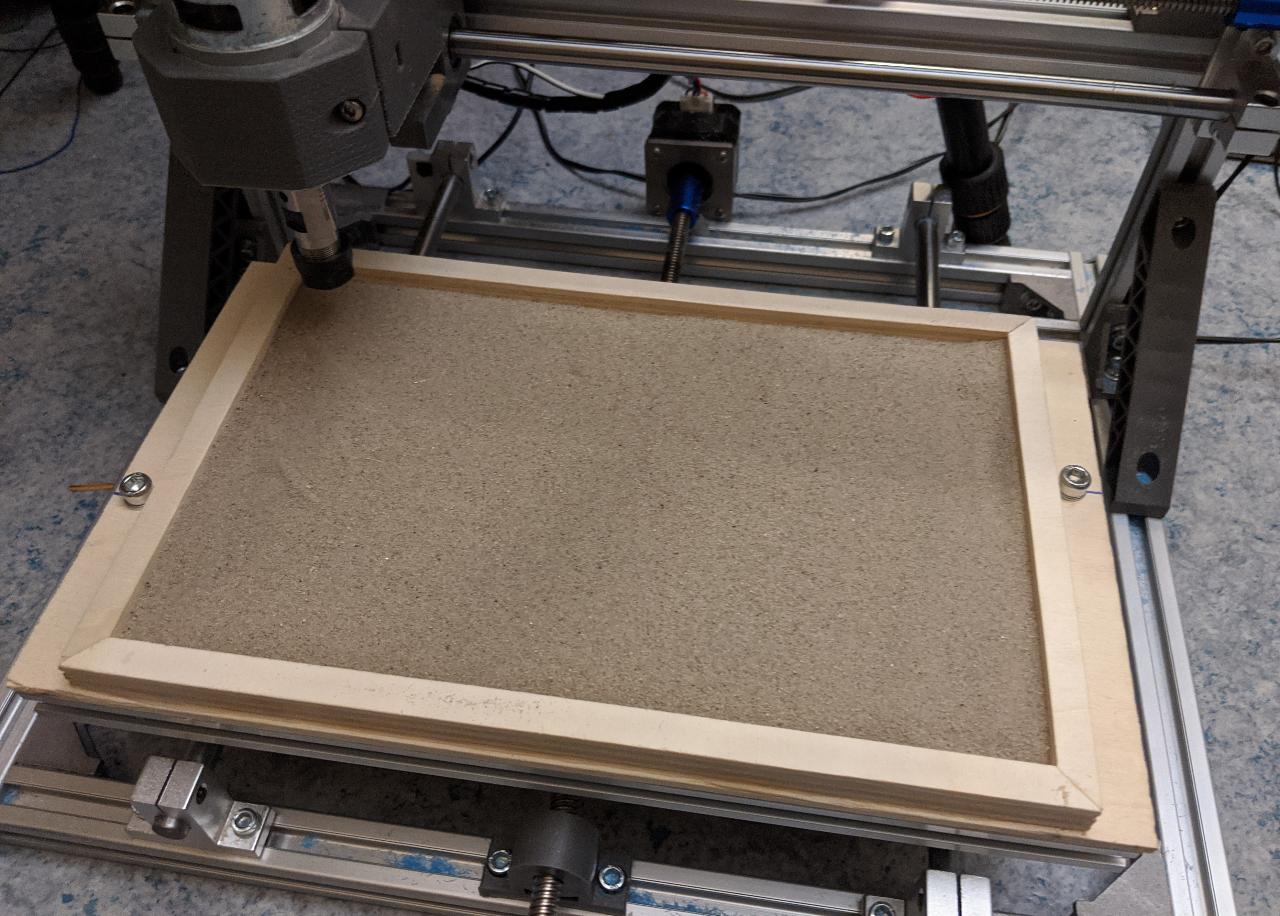
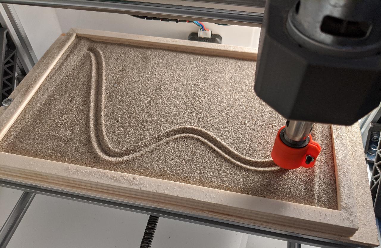
After cutting the angles at 45° and gluing everything onto a 4mm platform, I assemble the sandbox and place it onto my home CNC, which is a classic 3018 model.
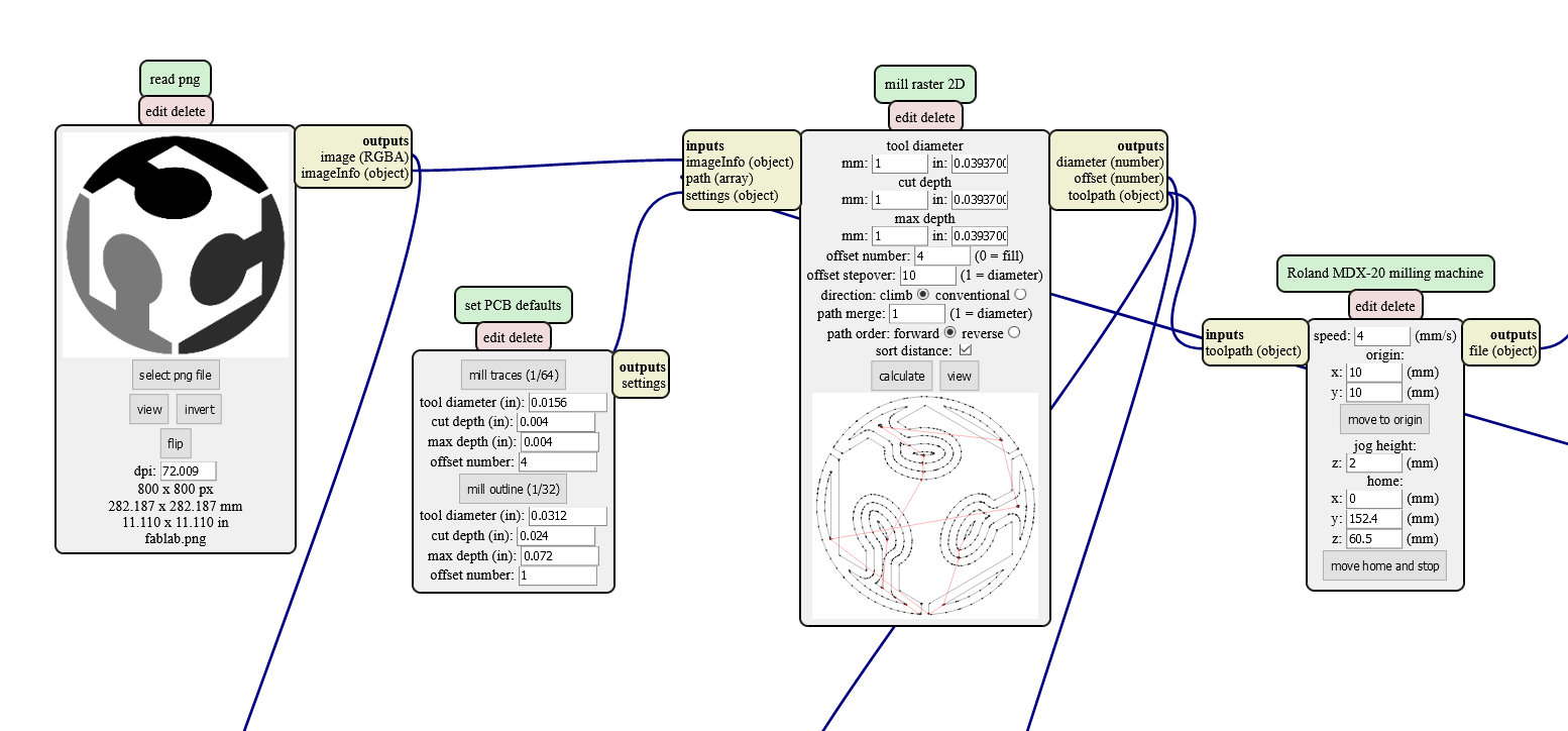
Before further modifying the CNC, I needed to see a proof of concept drawing. This was quickly achieved with the mill 2D png mods module. In this case, I use a large value for the stepover, because I want the lines to have a good separation.
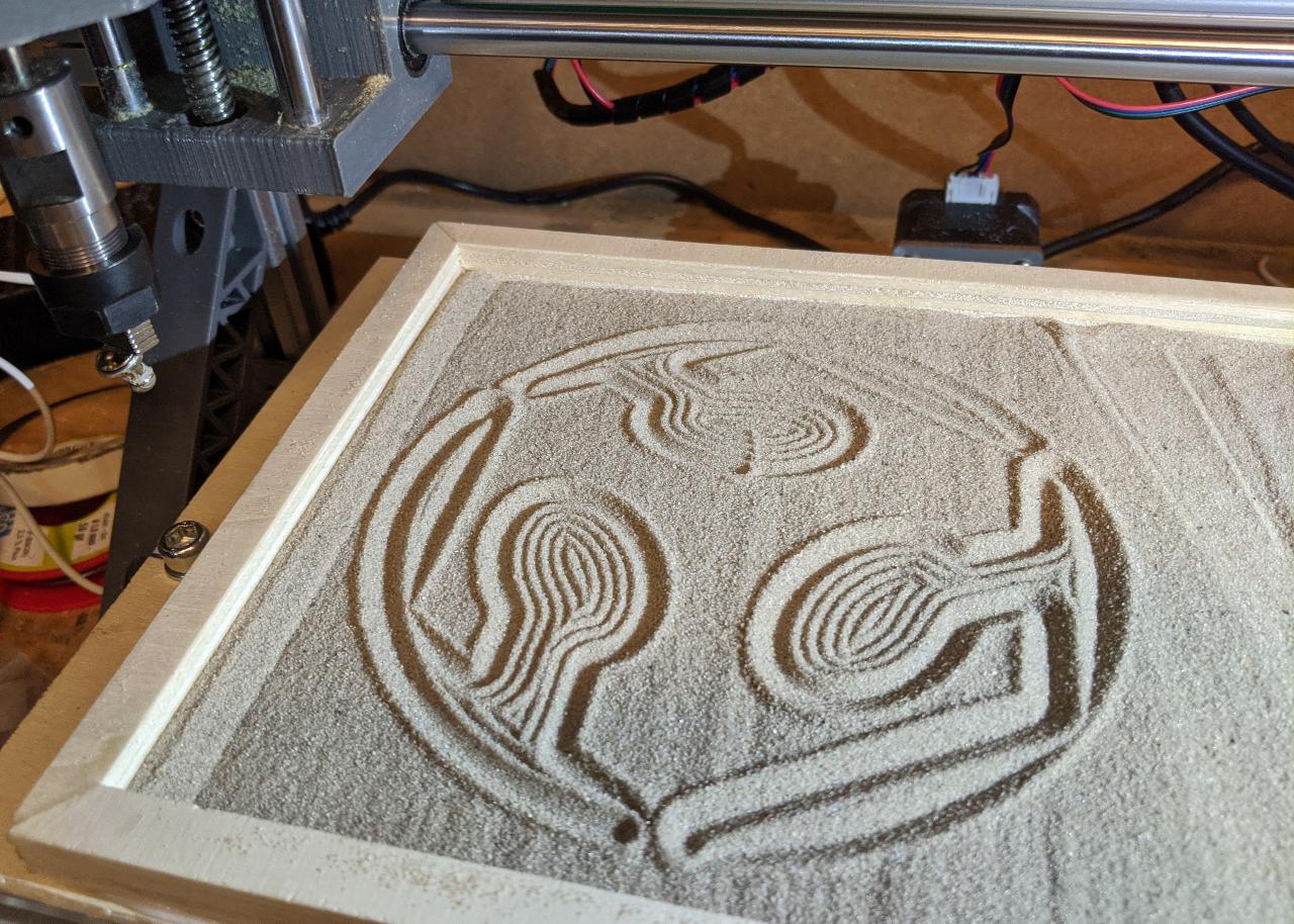
To test the drawing, I attached some magnets onto the toolhead. The result was OK:
For my final toolhead, I want to have several options, so I design a generic head with some embedded magnets. I will 3D print it in PLA with 0.2mm layer height.
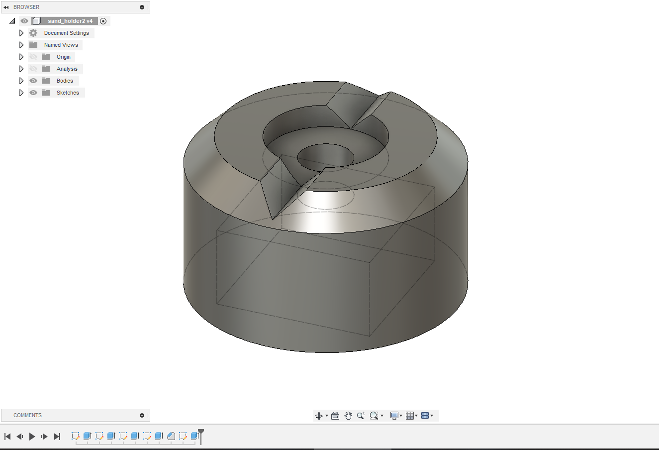
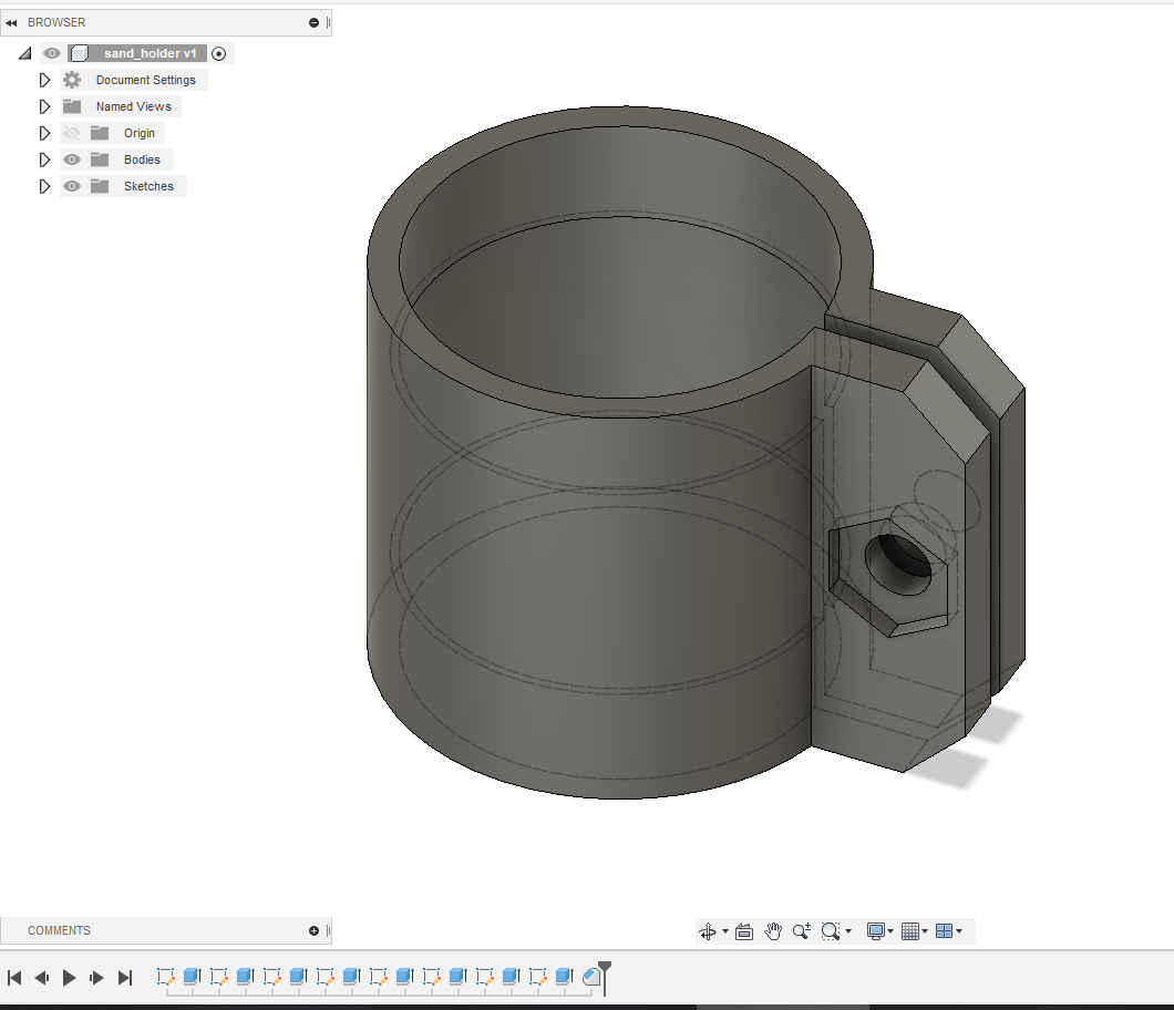
To attach it to the CNC head, I also prepare a 19mm adapter.
The parts are ready, along with the stack of 10x10mm neodymium magnets.
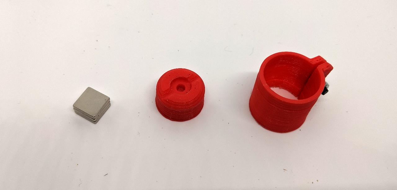
There are 3 different tools that can be attached onto the magnetic toolhead. The rake is designed to quickly flatten the sand, however I could not try it myself due to time constraints. You’re welcome to try it yourself using the files at the end of this page.
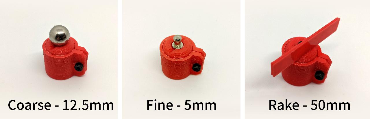
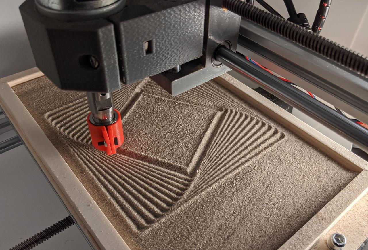
The coarse tool is simply a ball used in magnetic toys. The fine tool is part of a sew-on button.
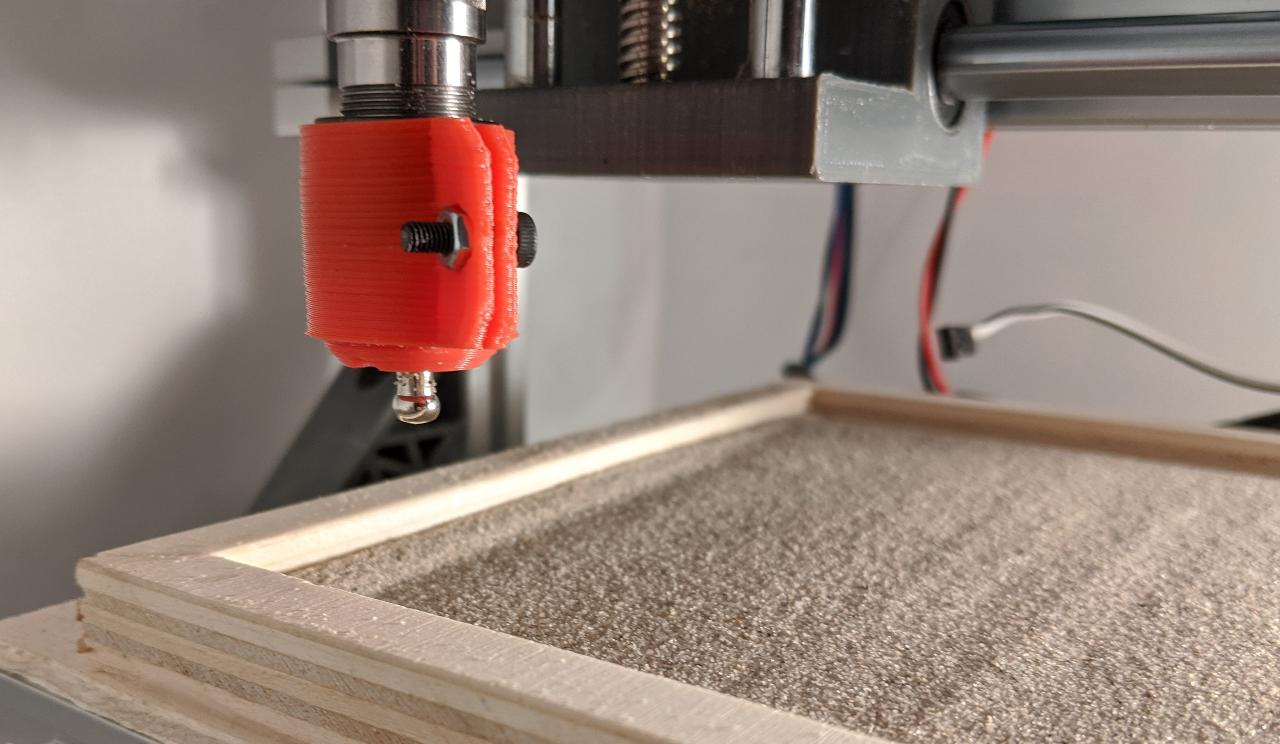
Attaching the tool onto the CNC causes no issue, and the spindle motor has enough torque at resting position to keep the toolhead aligned. All tools except the rake have radial symmetry so it wouldn’t be an issue anyhow.
Connecting the camera
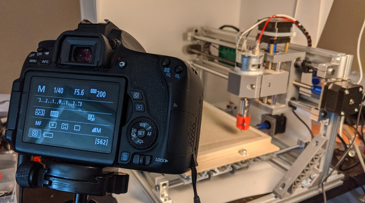
For convenience, I would like to automate the process of capturing pictures. One application of this is a timelapse video in which the sand drawing gets completed step-by-step. I use a Canon EOS 760D with minor modifications: a DC connector to power up the camera from an external power supply, and a 2.5mm jack to trigger it automatically.
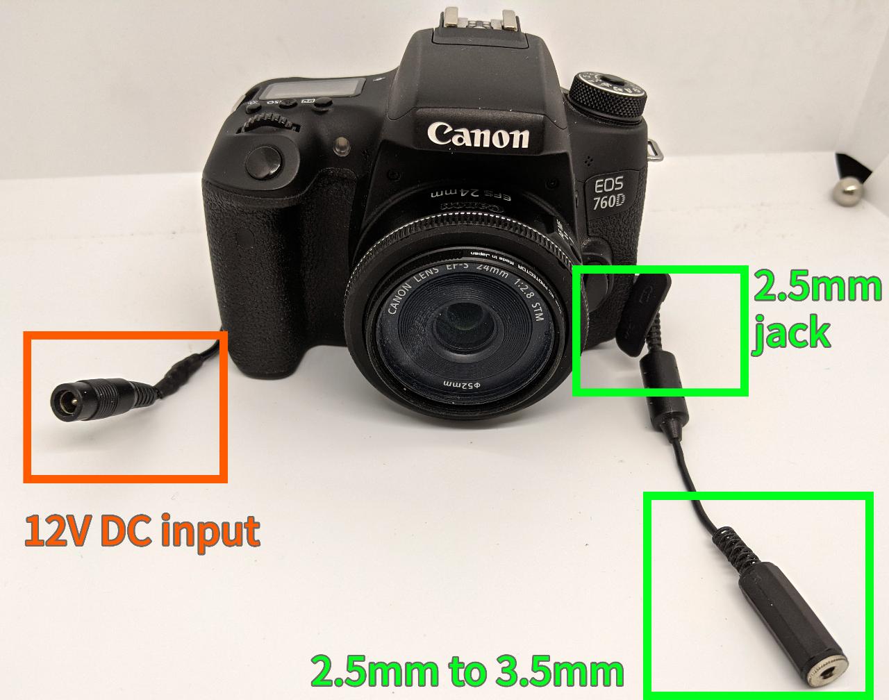
The DC connector emulates a LP-E17 battery pack using a 12V to 7.2V voltage adapter. I might write a tutorial on this on a separate webpage.
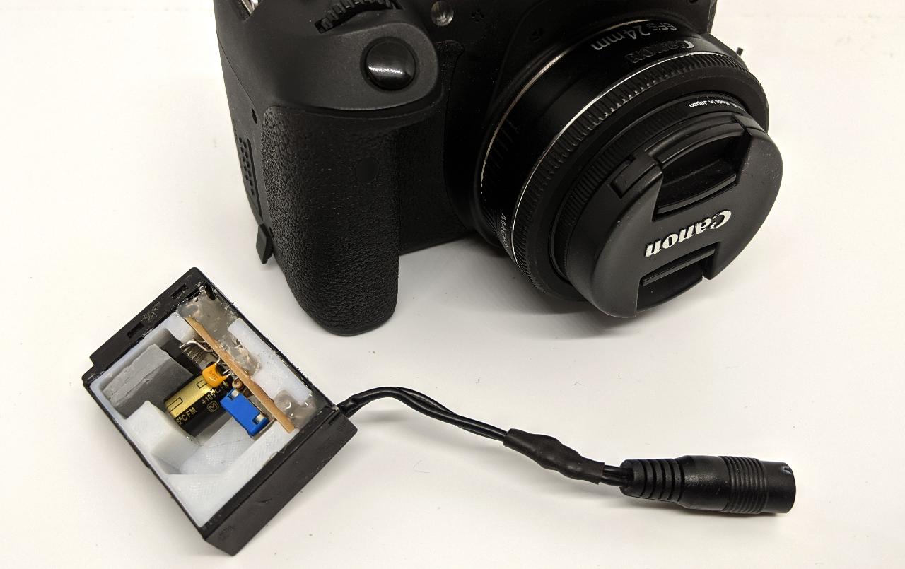
Triggering a Canon camera is surprisingly simple: you simply need to close a contact on the 2.5mm jack input (source: https://www.doc-diy.net/photo/eos_wired_remote/).
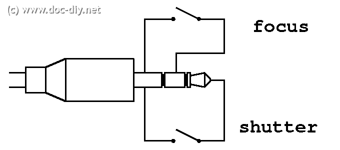
There is an internal 3.3V pull-up on the shutter pin, so I could find a way to trigger it from my CNC’s motherboard with a transistor. In the end, I decide to use a physical switch placed on the side of the machine. There are several reasons for this:
- This makes it compatible with any existing CNC.
- This ensures the camera is only be triggered when the toolhead is at a fixed position outside the build area.
- There is no need to modify the CNC’s firmware, a simple set of gcode commands will trigger the switch by moving at the right location.
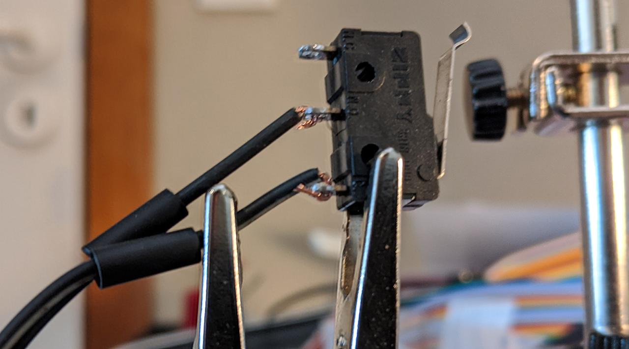
I use a typical endstop switch for this:
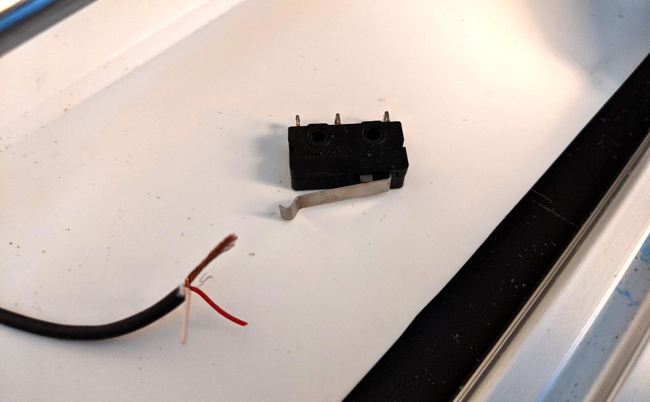
I need to connect the common (C) and normally open (NC) to the audio jack.
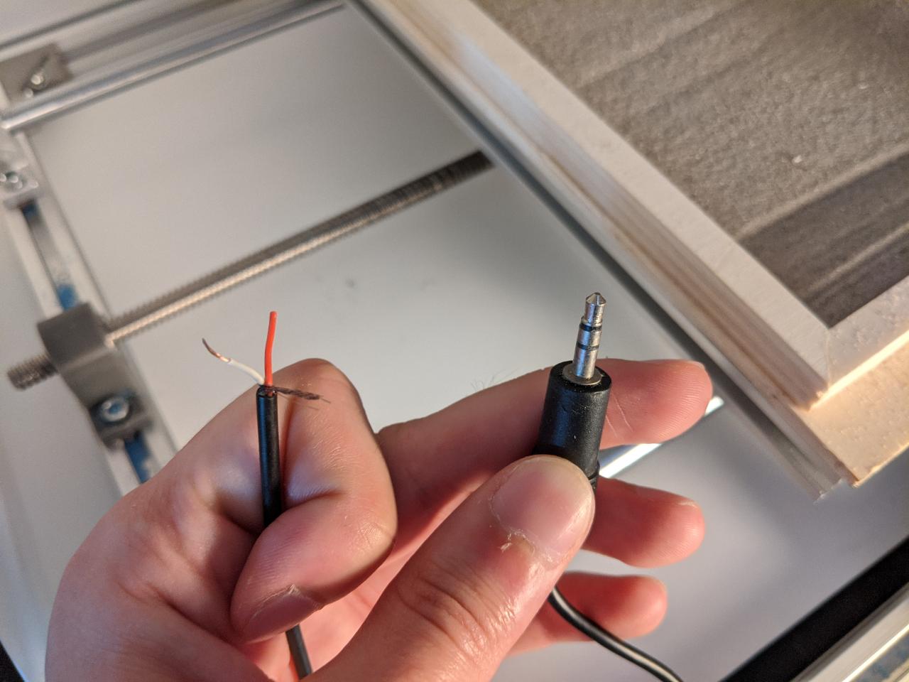
When soldering the switch, I prepare some heatshrink tubes to protect the contacts. Otherwise, there some unwanted short might happen.
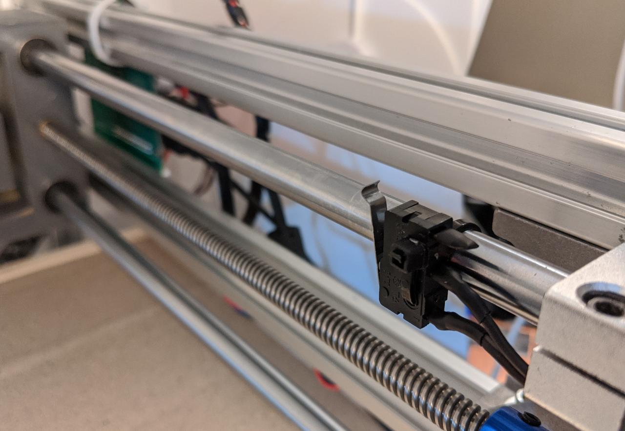
I place the switch on the right side of the X axis. On my CNC, the homing endstop is on the left, so this will not get in the way.
This simple gcode triggers the camera by gently touching the switch:
G1 Z12 F800
G1 X217 Y112 F800
G1 X219 F200
G1 X217 F200
THis code can be inserted at any point during an existing routine. It is important to return to the current position afterwards, I will show how to achieve this in the next section.
I power up the camera and connect the switch:
Here is a video of a simple trigger test:
Producing shapes with Python
As part of the assignment, I want to generate original shapes, well-suited for drawing in the sand.
I start by writing this simple gcode writer class. An XY curve can be added as a 2D array of N-by-2. The Z-axis is controlled to be lifted between curves, (or not, optionally).
class GcodeWriter:
    def __init__(self, z_up=2, z_down=-1, feedrate=800):
        self.gcode = "G54\n"
        self.z_up = z_up
        self.z_down = z_down
        self.xyz = (0, 0, 0)
        self.feedrate = feedrate

    def add_curve(self, xy_curve, z_curve=None, feedrate=None, lift=True):
        if z_curve is None:
            z_curve = self.z_down
        if feedrate is None:
            feedrate = self.feedrate

        x, y, z = self.xyz
        self.gcode += "F{:.2f}\n".format(feedrate)
        for i in range(len(xy_curve)):
            x, y = xy_curve[i]
            self.gcode += "G1 X{:.2f} Y{:.2f}\n".format(x, y)
            if i == 0:
                # first move, act on Z
                self.gcode += "G1 Z{:.2f}\n".format(z_curve)
                z = z_curve
        if lift:
            z = self.z_up
            self.gcode += "G1 Z{:.2f}\n".format(z)
        self.xyz = (x, y, z)

    def goto(self, x, y, z=None, feedrate=None):
        if feedrate is None:
            feedrate = self.feedrate
        x_c, y_c, z_c = self.xyz
        if z is None:
            z = z_c
        self.gcode += "G1 X{:.2f} Y{:.2f} Z{:.2f} F{:.2f}\n".format(x, y, z, feedrate)

    def save(self, filename):
        with open(filename, "w") as f:
            f.write(self.gcode)
On simple kind of drawing is repeating a shape with a decreasing size and slight rotation. The following function repeats an axisting shape provided as an N-by-2 array:
import numpy as np

def repeat_shape(shape, theta, scale, n):
    n_p = shape.shape[0]
    shape_tot = np.zeros((n, n_p, 2))

    R = scale*np.array([[math.cos(theta), math.sin(theta)],
                        [-math.sin(theta), math.cos(theta)]])
    for i in range(n):
        shape_tot[i, :, :] = shape
        shape = np.dot(shape, R)
    return shape_tot
You can find an example of this in the next section. Another type of drawing I want to try is called a siprograph. This is simething you obtain by rolling a disk onto another, and tracing the motion of a given point attached onto the secondary disk. This makes a great toy for kids (source: https://nathanfriend.io/inspirograph/):
I write my own function taking three radii as parameter: the main wheel radius (r1), secondary radius (r2), and the radius of the attached point (r3), which can be larger than r2. Computing the number of required turns to close the loop is a tricky thing, so I make the simplifying assumption that r1 and r2 are integers. The least common multiple (lcm) or r1 and r2 provides the number of required turns of the secondary wheel for a closed loop.
def lcm(a, b):
    return abs(a*b) // math.gcd(a, b)

def spirograph(r1, r2, r3, dtheta=0.05):
    # round number radii are assumed
    r1_round = round(abs(r1))
    r2_round = round(abs(r2))
    r1_r2_lcm = lcm(r1_round, r2_round)
    turns = r1_r2_lcm/r2_round

    n = round(2*math.pi*turns/dtheta)
    theta = np.linspace(0, 2*math.pi*turns, n)
    v1 = np.zeros((n, 2))
    v2 = np.zeros((n, 2))

    roll = r2*theta
    theta_main = roll/r1

    v1[:, 0] = r1*np.cos(theta_main)
    v1[:, 1] = r1*np.sin(theta_main)
    v2[:, 0] = r3*np.cos(theta_main+theta)
    v2[:, 1] = r3*np.sin(theta_main+theta)

    xy = v1+v2

    return xy
Because The drawings don’t have millimeter units at this stage, I also provide a function for rescaling the drawing into a rectangle of specified dimensions. For my CNC, I set (x1, y1, x2, y2) to (0, 0, 205, 128) in mm units.
def fit_rectangle(shape, x1, y1, x2, y2):
    n_dim = len(shape.shape)
    min_all = np.min(shape, axis=tuple(range(n_dim-1)))
    max_all = np.max(shape, axis=tuple(range(n_dim-1)))
    x1_s, y1_s = min_all[:]
    x2_s, y2_s = max_all[:]

    w, h = x2-x1, y2-y1
    w_s, h_s = x2_s-x1_s, y2_s-y1_s
    ratio = w/h
    ratio_s = w_s/h_s
    center = np.array([x1*0.5+x2*0.5,
                       y1*0.5+y2*0.5])
    center_s = np.array([x1_s*0.5+x2_s*0.5,
                         y1_s*0.5+y2_s*0.5])

    use_x = ratio < ratio_s
    scale = w/w_s if use_x else h/h_s

    shape_new = (shape-center_s)*scale + center
    return shape_new
In the Python code archive, you can also find the insert_gcode() function which is intended for inserting camera trigger operations into an existing gcode at given time intervals. This works by doing a very rough parsing of the gcode to know the current position and feedrate, and keep track of the time spent on each operations. If the time since the last camera trigger is greater or equal than the specified interval, the camera trigger gcode is inserted resulting in this type of interruption in the gcode (notice the comments in parentheses):
G1 X100.29 Y107.84
(INSERT)
G1 Z12 F800
G1 X217 Y112 F800
G1 X219 F200
G1 X217 F200
(RETURN)
F800.00
G1 X100.29 Y107.84
G1 Z8.00
(CONTINUE)
G1 Z4.00
Results
Repeating shapes
As a first test, I want to make a video timelapse of a sequence of squares, decreasing in sizes. This easily achieved with repeat_shape(square, 0.05, 0.95, 30) where square is a 2D array describing a centered square. I plot the result with the matplotlib library:

I launch the drawing on the CNC from my PC using any standard gcode streamer. For this drawing, I use my 5mm toolhead:
A camera trigger is inserted every 5 seconds, which is highly time consuming. The resulting timelapse is pretty fun to watch:
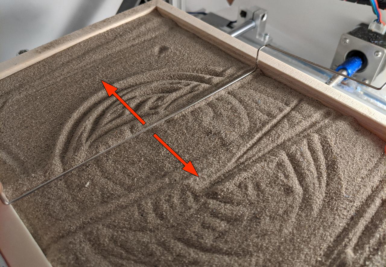
To reset the sandbox, I use a simple metal rod. In the future, I would want the CNC to fetch the rake tool, and cleanup its own mess automatically. Switching tools should be possible thanks to the magnetic toolhead, but this was not tested yet.
Spirograph
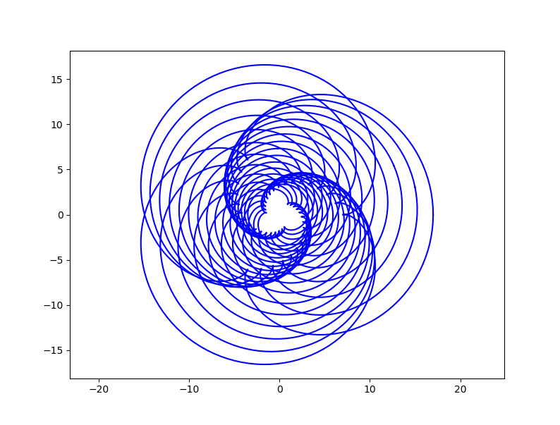
As a second demo, I generate a spirograph with spirograph(100, 2, 80):
This time again, I stop the operations frequently to shoot pictures, making the total runtime about 1 hour long instead of 10 minutes.
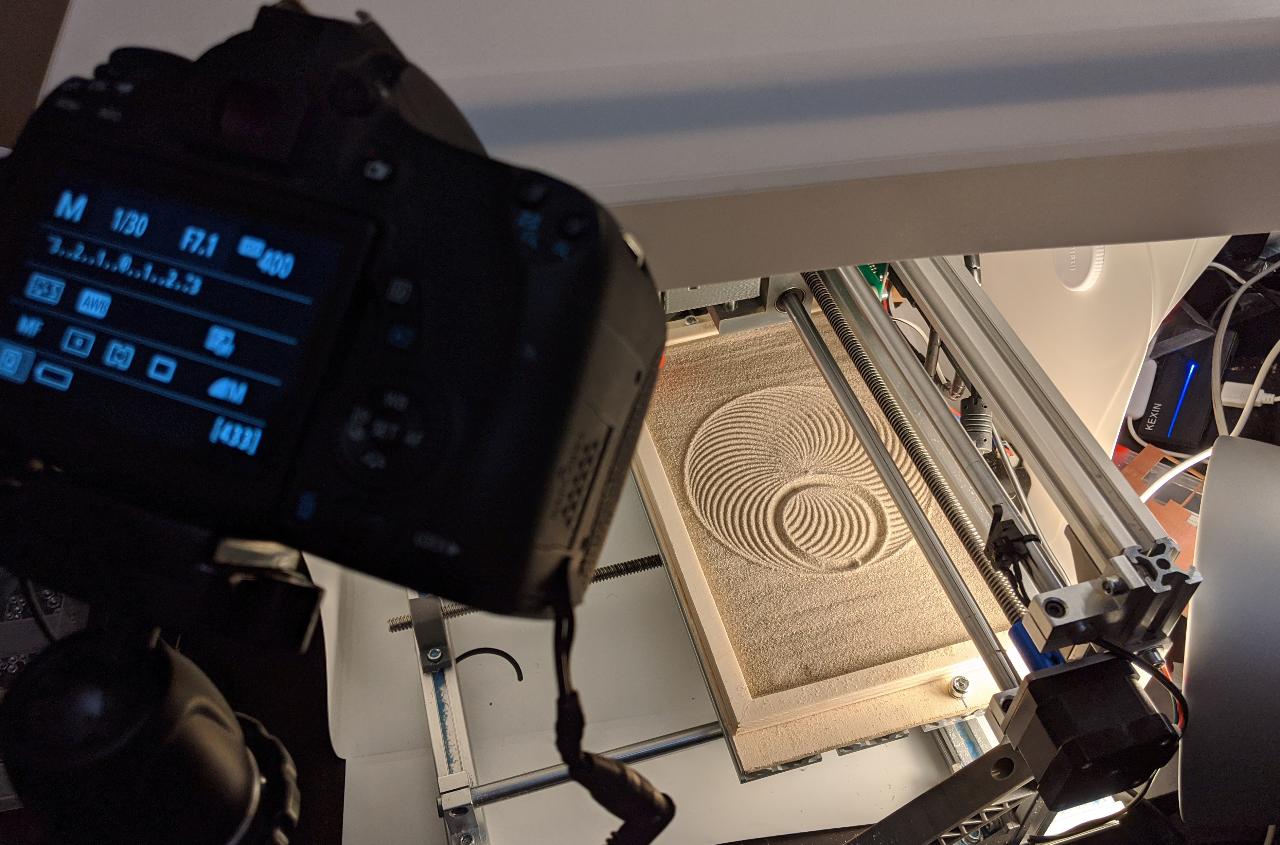
The timelapse video was worth the wait:
Plotting curves
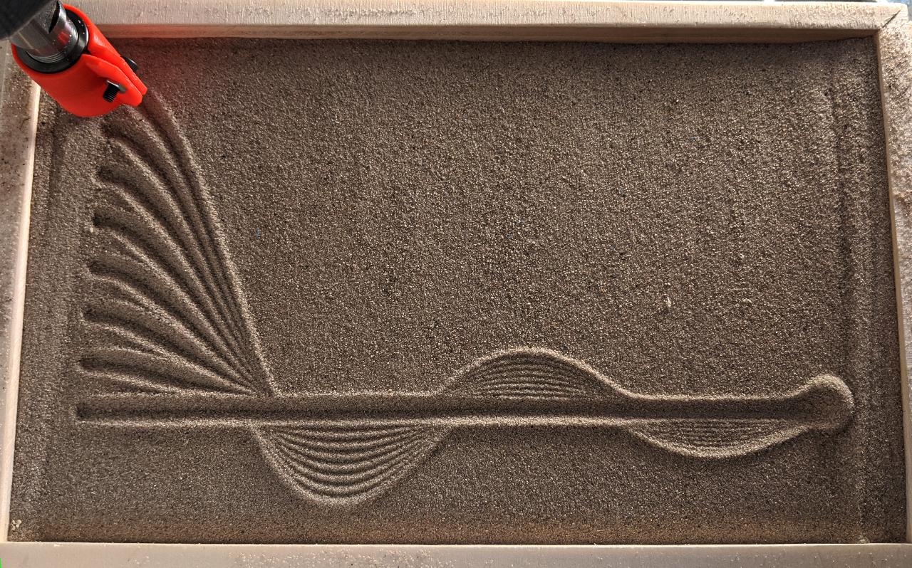
Next, I tested some graph plotting using arbitrary calls to GcodeWriter.add_curve(). I choose to depict the sinc() function, which is a very important function for engineers and physicists:
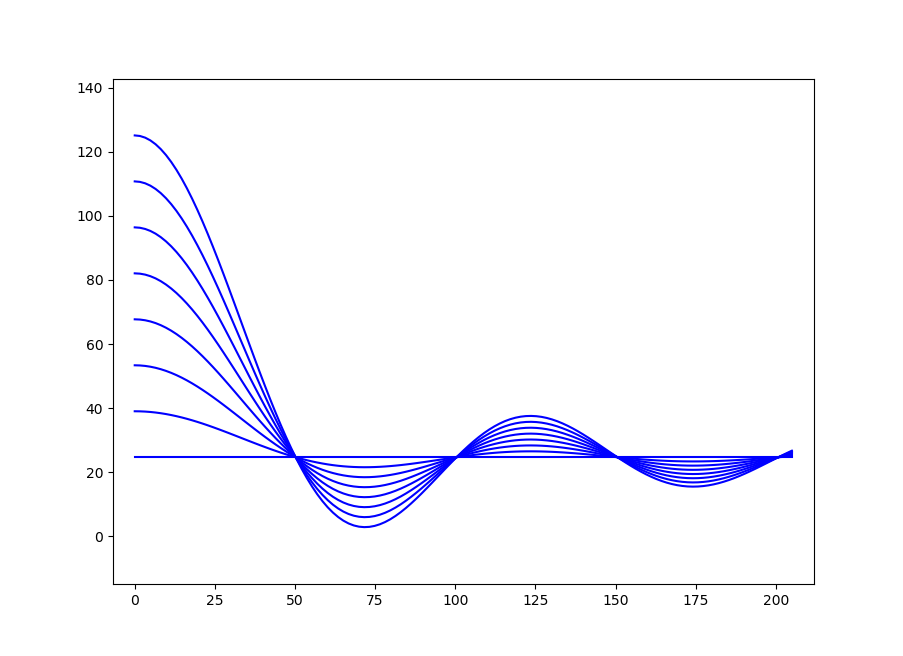
Plotting a single curve shows the high accuracy of the toolhead.
Here is the complete drawing:
Repeating spirograph
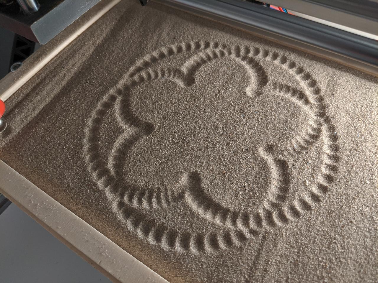
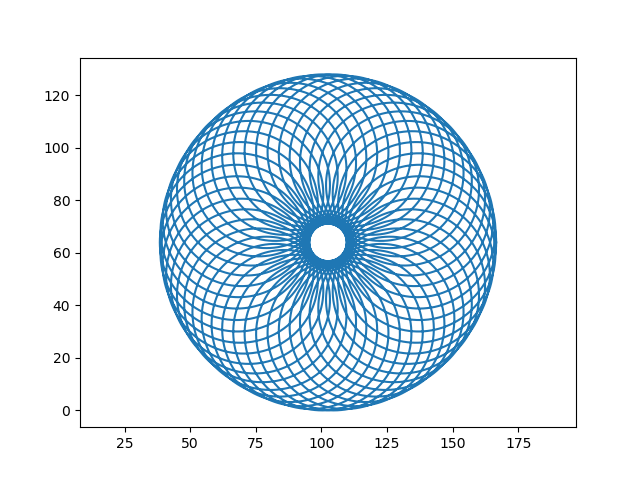
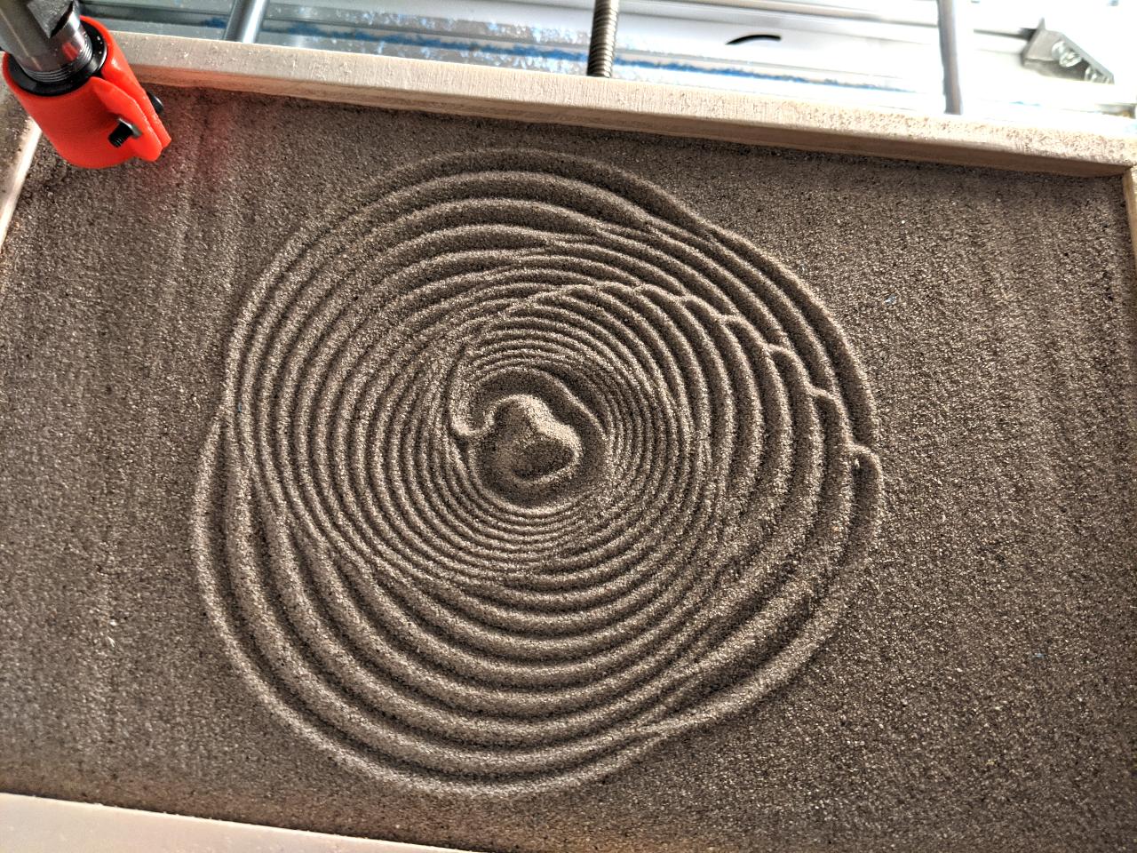
The repeat_shape() and spirograph() functions can also be combined to create mroe complex shapes. I demonstrate this by starting with a simple spirograph:

I then repeat it with decreasing size:
The result is not perfect because of the lifting operations, visible on the upper right side of the drawing. This shows that the start/end of each curve should be placed carefully to prevent this kind of artifact.
Dots
Finally, I try out the spherical toolhead to draw dots instead of curves. This is a trivial case of GcodeWriter.add_curve() being repeatedly called with an array containing a single point and with lift set to True to lift the toolhead after each operation.
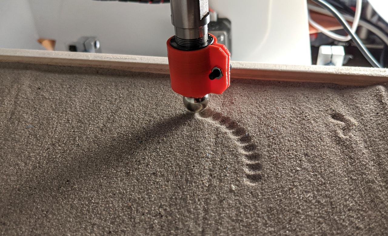
The following video shows a few dots being made:
The final drawing shows the type of effect that can be achieved with this method: