10. Input devices
This week’s assignment is centered around electronics input devices. This includes any kind of analog or digital sensor that can be interfaced with a microcontroller. In the group assignment, we have calibrated and tested the analog input in an ATtin1614.
I will focus on two small projects:
- An alarm system based on an HC-SR04 and a DS1302 RTC module for timekeeping.
- A tilt gamepad with some mercury switches.
In any project, it is important to read the documenation of each input device, to make sure the use case is safe and meaningful.
Realtime distance alarm
While looking for unused input devices at home, I found a DS1302 RTC module, and a HC-SR04:
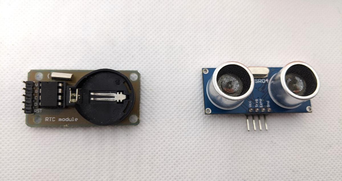
The DS1302 RTC (realtime clock) has the following features:
- set the current time (up to a second precision).
- keep track of the current year/month/day with leap year compensation.
- compute the day of the week.
In my case, the crystal oscillator (32.768kHz) is already mounted, and there is an optional slot for a battery.
The HC-SR04 is an ultrasonic distance sensor which sends a short burst when requested, and returns a signal when the echo of the burst is first detected.
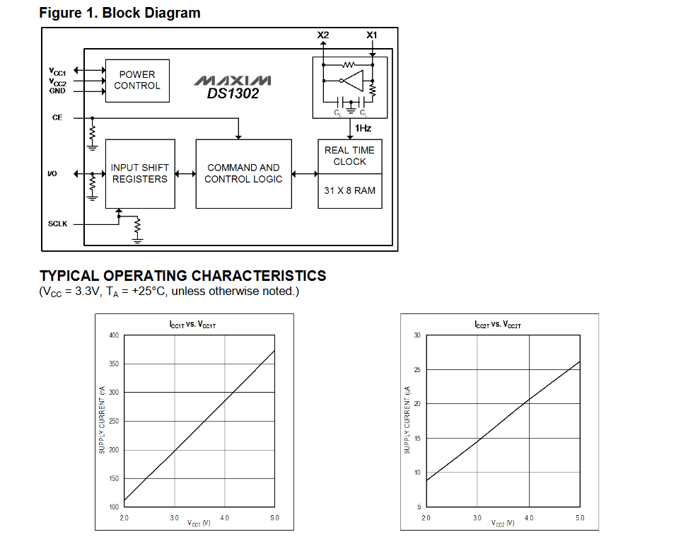
The HC-SR04 is designed for a 5V use. I checked the datasheet of the DS1302 to make sure it can also operate at that voltage, and I find that the maximal supply voltage is 5.5V.
For this project, I decided to use my ATtiny1614 controller board that I previously designed. The main reason is that it can operate at 5V, and it has plenty of available pins to connect temporary projects onto it. I also add a USB-UART on the serial port of the ATtiny1614 to communicate with it.

I connect the DS1302 in the following way:
- RST -> GPIO 0
- DAT -> GPIO 1
- CLK -> GPIO 2
The HC-SR04 requires only two connections:
- TRIG -> GPIO 6
- ECHO -> GPIO 7
Finally, the USB-SERIAL can only be connected to the RX/TX pins of the ATtiny1614:
- TX -> GPIO 4 (RX)
- RX -> GPIO 5 (TX)
I start by programming the DS1302. I found an Arduino library that handles the low-level communication for me, which is basically sending/receiving individual bits on the bidirectional DAT connection. I had to add a 1{\rm k\Omega} resistor on the DAT to have a relieable transmission. Otherwise, some bits are simply random (most likely due to a wrong logic level). In the Arduino IDE, I start a new sketch and include the DS1302:
#include <DS1302.h>

#define RTC_RST 0
#define RTC_DAT 1
#define RTC_CLK 2

DS1302 rtc(RTC_RST, RTC_DAT, RTC_CLK);

void setup() {
  rtc.halt(false);
  rtc.writeProtect(false);
  rtc.setTCR(TCR_OFF);

  rtc.setDate(1, 1, 2020);
  rtc.setTime(12, 0, 0);
  rtc.setDOW(WEDNESDAY);

  Serial.begin(9600);
}

void loop() {
  Serial.print(t.year);
  Serial.print("-");
  Serial.print(t.mon);
  Serial.print("-");
  Serial.print(t.date);
  Serial.print(" ");
  Serial.print(t.hour);
  Serial.print(":");
  Serial.print(t.min);
  Serial.print(":");
  Serial.println(t.sec);

  delay(1000);
}
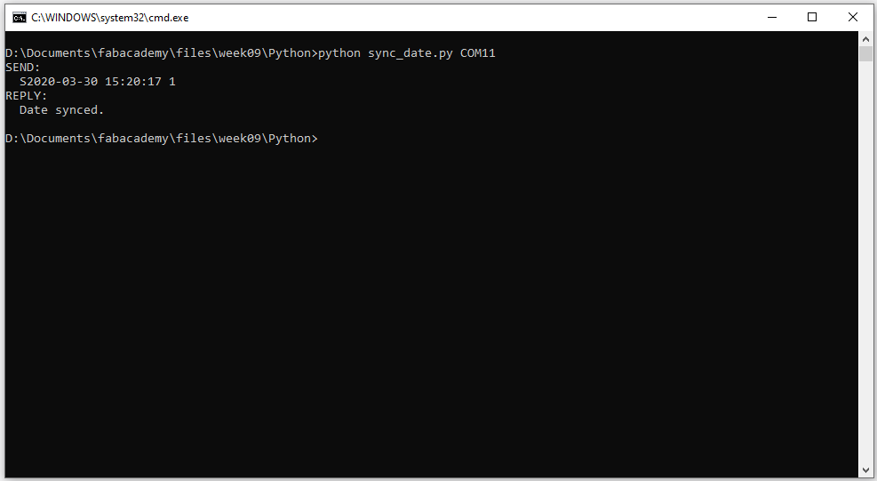
This simple code sets the current time to a dummy value and tests the timekeeping ability of the DS1302 by sending the current date/time to the PC through the serial connection. This worked without issue, but I needed a way to synchronize the time using the PC. I wrote a simple script that sends the current time as S<YYYY>-<MM>-<DD> <HH>:<mm>:<ss> <DOW> where S is a constant first character to indicate that a new sync is about to arrive, and <DOW> is the day of the week (1-7).
import datetime
import serial
import argparse


def parse_arguments():
    usage_text = (
        "Usage:  python sync_date.py [PORT]\n"
    )
    parser = argparse.ArgumentParser(description=usage_text)
    parser.add_argument("port", nargs=1, help="Serial port")
    return parser.parse_known_args()


def sync_date(ser):
    # n = datetime.datetime.now()
    n = datetime.datetime(2020, 3, 30, 15, 20, 17)
    txt = "S{:04}-{:02}-{:02} {:02}:{:02}:{:02} {}\n".format(n.year,
                                                             n.month,
                                                             n.day,
                                                             n.hour,
                                                             n.minute,
                                                             n.second,
                                                             1+n.weekday())
    txt_b = bytes(txt, "ascii")
    ser.write(txt_b)
    print("SEND:\n  {}".format(txt.strip()))
    reply = ser.readline().decode("ascii")
    print("REPLY:\n  {}".format(reply.strip()))


def main():
    args, _ = parse_arguments()

    port = args.port[0]

    s = serial.Serial(port, timeout=1)
    sync_date(s)
    s.close()


if __name__ == "__main__":
    main()
You will find the full code for the ATtiny at the end of this page. When syncing the date with the Python script, the ATtiny1614 replies with “Date synced” in case of success:
I then started programming the HC-SR04. I use this simple function that sends a pulse on the TRIGGER pin then measures the delay for the reply:
#define SR04_TRIG 6
#define SR04_ECHO 7

#define DIST_TIMEOUT (25000UL)
#define SOUND_SPEED (0.340)

[...]

int measure_dist() {
  long measure;
  int measure_mm;
  digitalWrite(SR04_TRIG, HIGH);
  delayMicroseconds(10);
  digitalWrite(SR04_TRIG, LOW);

  measure = pulseIn(SR04_ECHO, HIGH, DIST_TIMEOUT);
  measure_mm = (int)(measure / 2.0 * SOUND_SPEED);
  return measure_mm;
}
Notice the speed of sound is assumed to be 0.340 mm/us, and the puleIn will timeout if no reply is received after 25000 us, which is about 8.5 meters and would be too far away in this project anyway. In the code, I add a hysteresis effect similar to a Schmitt trigger to make sure the alarm is not triggered all the time:
dist = measure_dist();
if (triggered) {
  if (dist > DIST_THRESH2) {
    triggered = 0;
  }
} else {
  if (dist < DIST_THRESH1) {
    triggered = 1;
    alarm(dist);
  }
}
I attach the ultrasonic sensor to an object to give it more character:

Assembling the code together, I now have an alarm sensor that sends a message on the serial port whenever a close object is detected. I program the chip with pyupdi.py, and test the result:
Tilt gamepad
For my second project, I wanted to make use of a forgotten bit of tech: the mercury tilt switch. It’s an extremely simple input device where a small mercury bead is trapped in a glass container and closes the circuit when tilted.
DISCLAIMER: mercury is a dangerous substance that is now banned in many countries. You should not attempt buying mercury switches from China, there are now safe alternatives based on accelerometers or simple metallic beads. The sensors I use in this project were acquired many years ago, and I will dispose of it after this project.
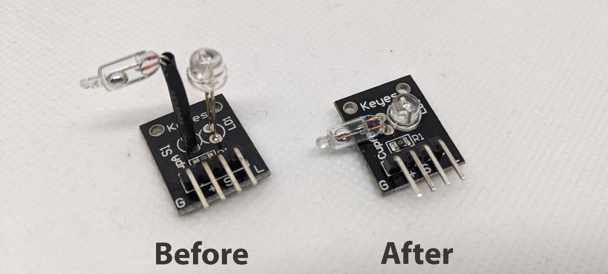
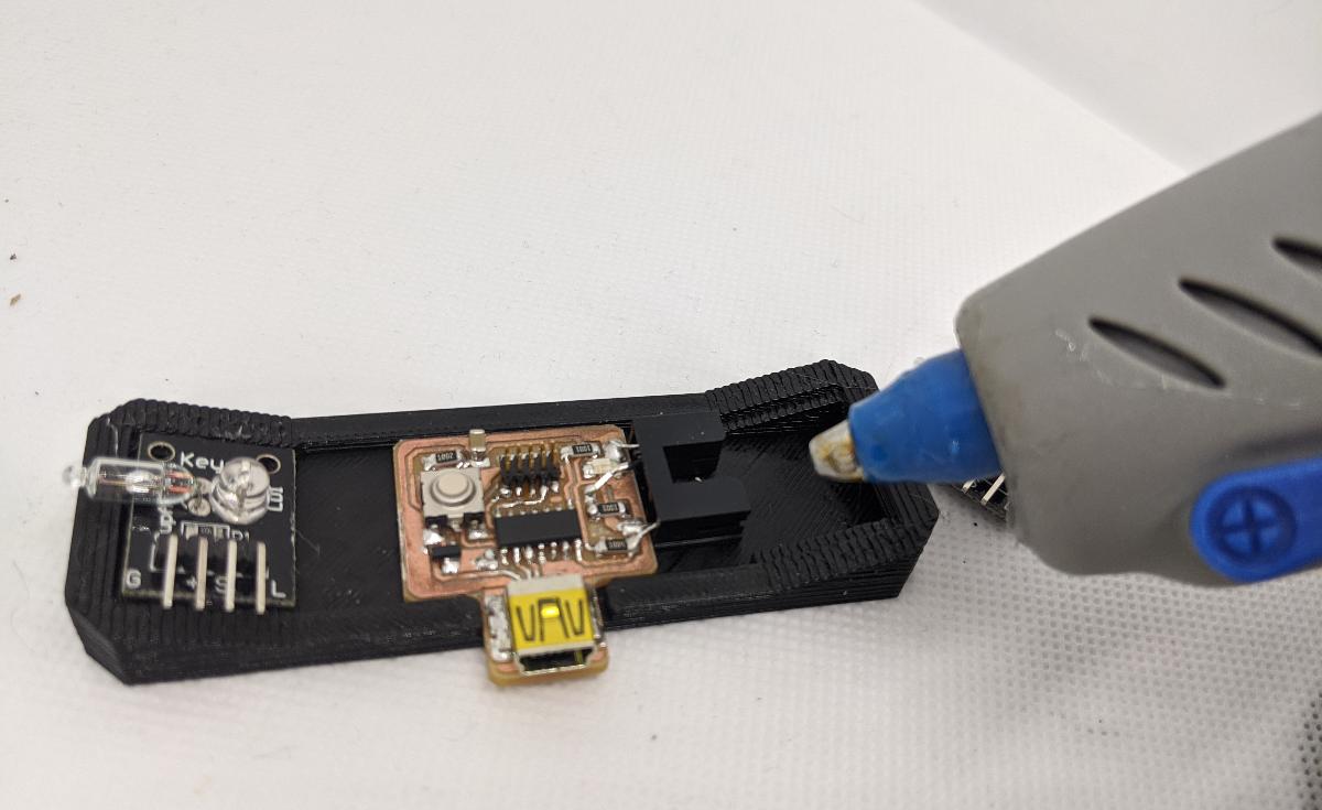
The sensor I found is a magical light cup module from Keyes, which inldues a pull-up resistor and an LED. However, I did not like the initial packaging, so I decided to lower the components using a soldering iron.
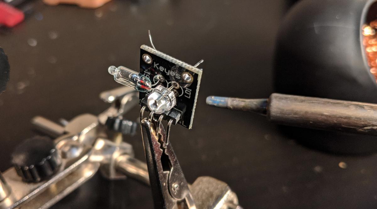
After the modification, the device is a lot more compact:
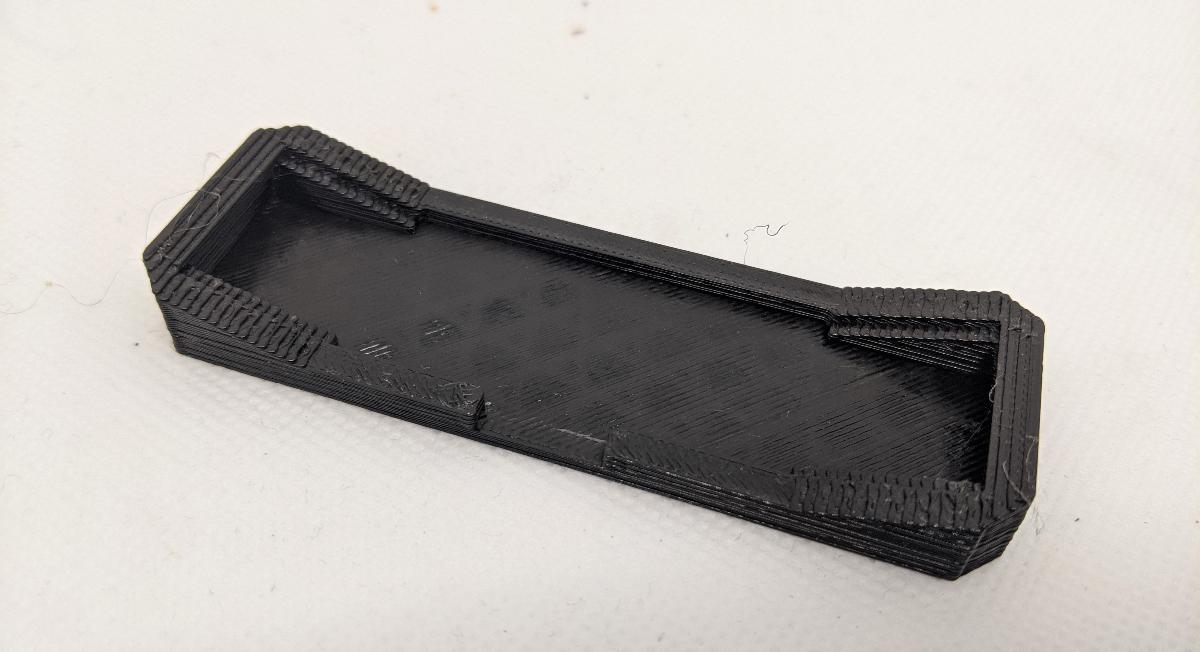
After preparing 2 sensors, I decided to 3D print a very simple gamepad to attach one of each side.
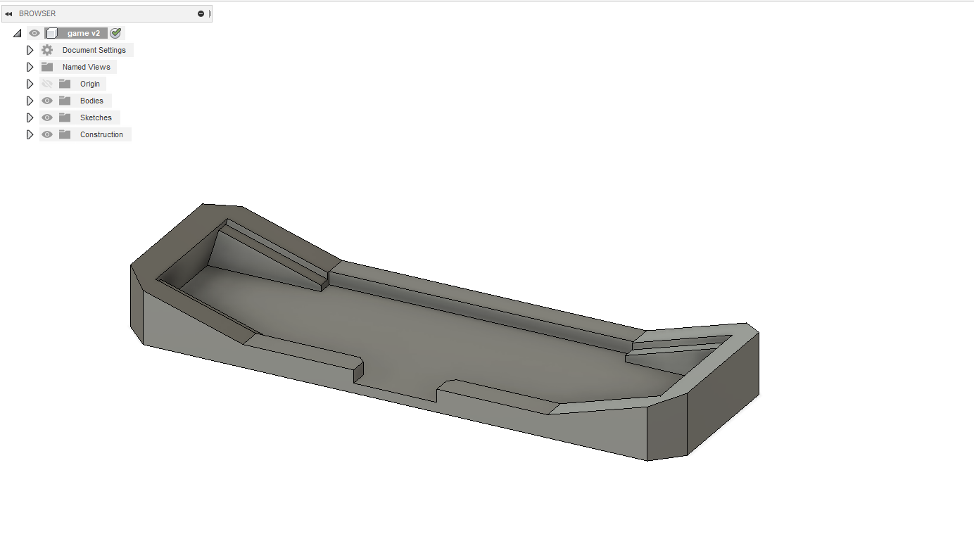
The 3D print came out OK at a layer height of 0.3mm and a 0.5mm nozzle.
I attach the sensors and the microcontroller to the gamepad. For this project, I am using my SAMD11C14 board, previously developed.
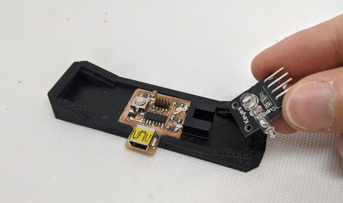
Because this project is only temporary, I use a glue gun to attach lightly each component.
Due to the covid-19 crisis in my country, I could not find a 1.25 mm pitch connector to interface with my chip. I had to improvise a bit using some wires:

The gamepad is complete! Notice how the sensors are tilted so that the resting state can be detected (both switches closed).
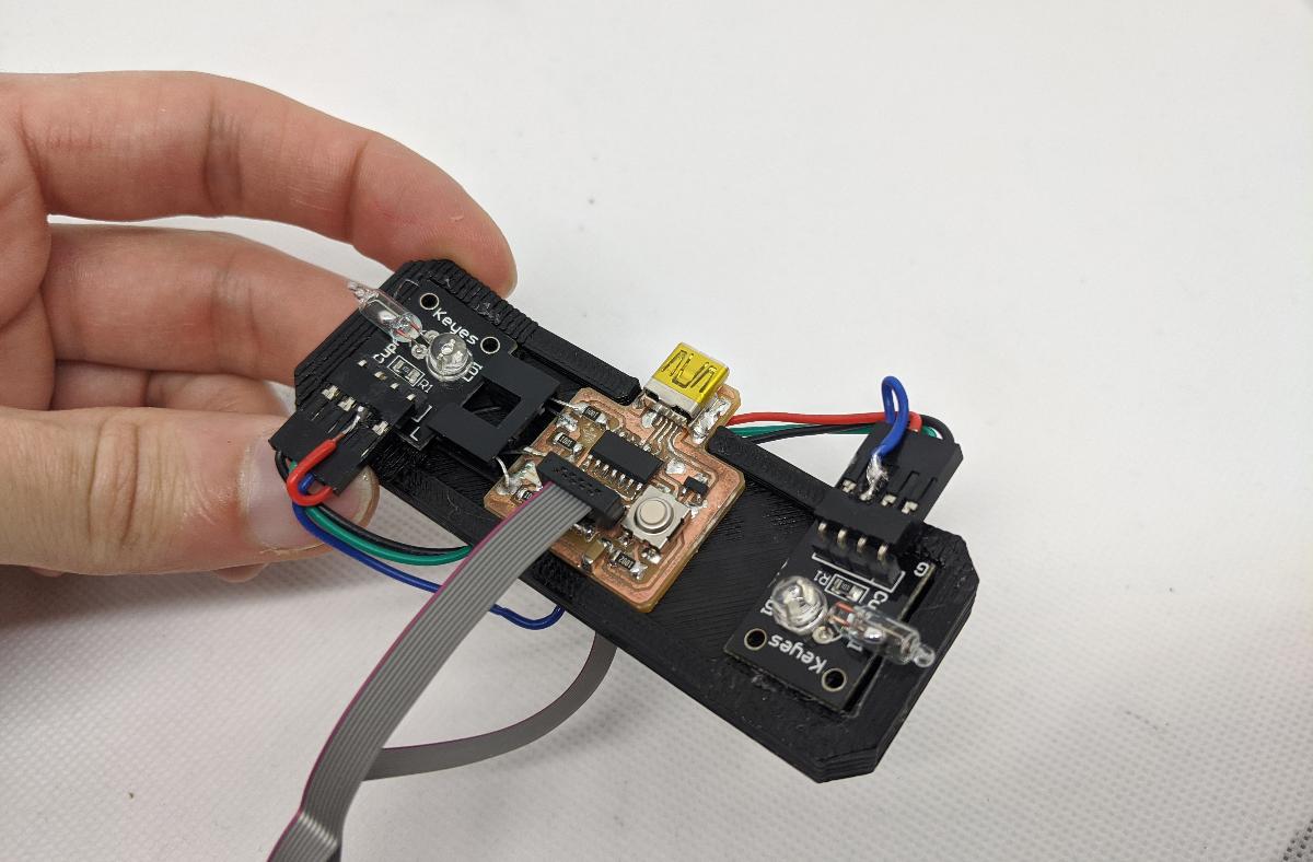
I connected the signal from each device to the only free pins on my board, which are normally used for programming the chip with JTAG:
- sensor left -> GPIO 30
- sensor right -> GPIO 31
The gamepad will be a lot more fun if it can emulate a keyboard. Thankfully, the D11C can emulate a HID device (mouse/keyboard etc.), and I can use the great Keyboard library from Arduino, because I loaded the Arduino core bootloader on my D11C. The gamepad should act as follows:
- tilted left: press left arrow
- tilted right: press right arrow
- not tilted: release arrows
- button: press/release space
Here is the full code of this project:
#include <Keyboard.h>

#define PIN_BUTTON 15
#define PIN_LEFT 30
#define PIN_RIGHT 31
#define PIN_LED 5

int state_lr = 0;
int state_b = 0;

int debug = 0;

void setup() {
  pinMode(PIN_BUTTON, INPUT);
  pinMode(PIN_LEFT, INPUT);
  pinMode(PIN_RIGHT, INPUT);
  pinMode(PIN_LED, OUTPUT);

  if (!digitalRead(PIN_BUTTON)) {
    // debug mode
    digitalWrite(PIN_LED, HIGH);
    Serial.begin(9600);
    debug = 1;
  } else {
    // normal mode
    Keyboard.begin();
  }
}


void loop() {
  int state_lr_n;
  int state_b_n;
  state_lr_n =  (digitalRead(PIN_LEFT)<<1) | digitalRead(PIN_RIGHT);
  state_b_n = !digitalRead(PIN_BUTTON);

  if (state_b_n != state_b) {
    if (debug) {
      Serial.print("button:");
      Serial.println(state_b_n);
    } else {
      if (state_b_n) {
        Keyboard.press(' ');
      } else {
        Keyboard.release(' ');
      }
    }
  }

  if (state_lr_n != state_lr) {
    if (debug) {
      Serial.print("state:");
      Serial.println(state_lr_n);
    } else {
      if ((state_lr_n & ~state_lr) & 0b01) {
        Keyboard.press(KEY_RIGHT_ARROW);
      }
      if ((~state_lr_n & state_lr) & 0b01) {
        Keyboard.release(KEY_RIGHT_ARROW);
      }
      if ((state_lr_n & ~state_lr) & 0b10) {
        Keyboard.press(KEY_LEFT_ARROW);
      }
      if ((~state_lr_n & state_lr) & 0b10) {
        Keyboard.release(KEY_LEFT_ARROW);
      }
    }
  }

  state_lr = state_lr_n;
  state_b = state_b_n;
  delay(10);
}
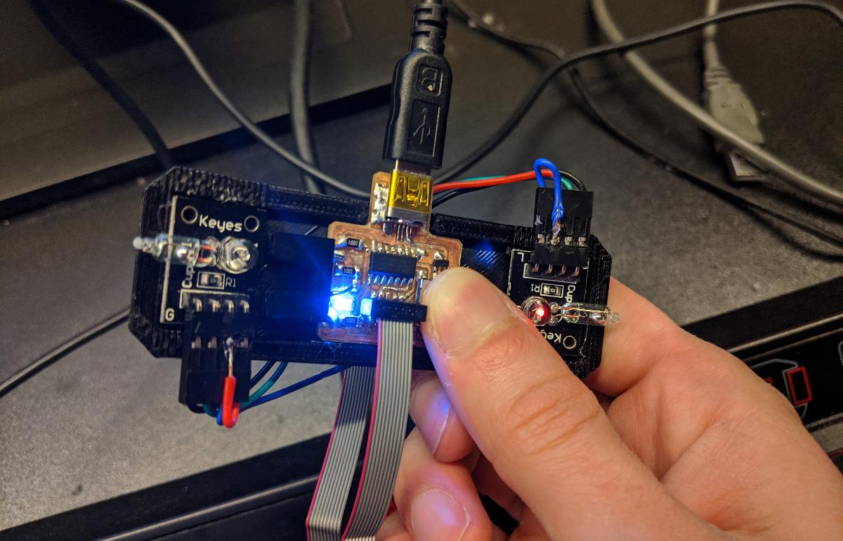
Note that the board can become very annoying to program when using the Keyboard library, as it will send keyboard strokes that cannot truly be prevented by your PC. Therefore, I added a safety feature using the on-board button switch: pressing the button when powering on the board will force it to enter a debug mode where no keystroke is sent. The on-board LED turns on when in debug mode:
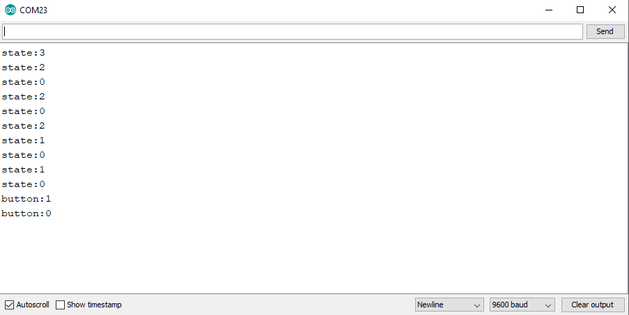
Instead of keeystrokes, I send serial data to the PC, useful for debugging. When I feel confident that the tilt sensors are working, I can launch the board in non-debug mode.
The gamepad is very fun to use! I found some games where only left/right and space keys are needed, and I can confirm that this project is very usable as an actual gamepad controller: