8. Computer controlled machining
This week’s assignment is centered around using a CNC machine to build something large. In our group assignment, we characterized our machine’s tolerance. We tested various speeds and settings for both MDF and plywood, and we found that the surface error was small enough to guarantee a good fit.
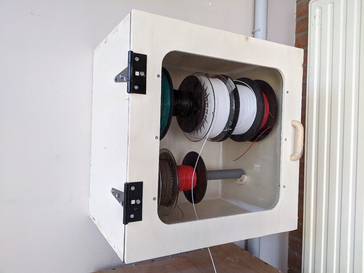
For my assignment, I decided to build an enclosure for my 3D printer filament. Its characteristics should be:
- Airtight: this prevents moisture to inflitrate the plastic filament, which can deteriorate its quality.
- Hanged on a wall: in my setup, I want the box to sit on top of the printer, which is located near a wall.
- Front door with a transparent door
- Hole on the bottom: the filament can be dispensed directly from the box.
I decide to use 12mm plywood for this project, as well as a PMMA panel for the front door, which will be lasercut.
Design
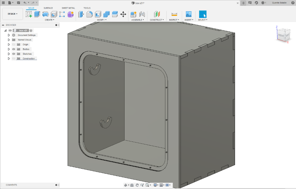
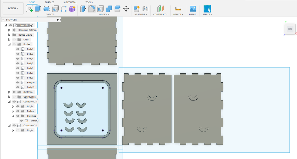
I started drawing the box in Fusion 360. The most interesting part was the way each side of the box would fit together. I used box joints for this purpose, as they are the simplest type of joint to implement. However, sharp corners cannot be achieved with a regular CNC. This will be solved later by drilling holes on every corner.
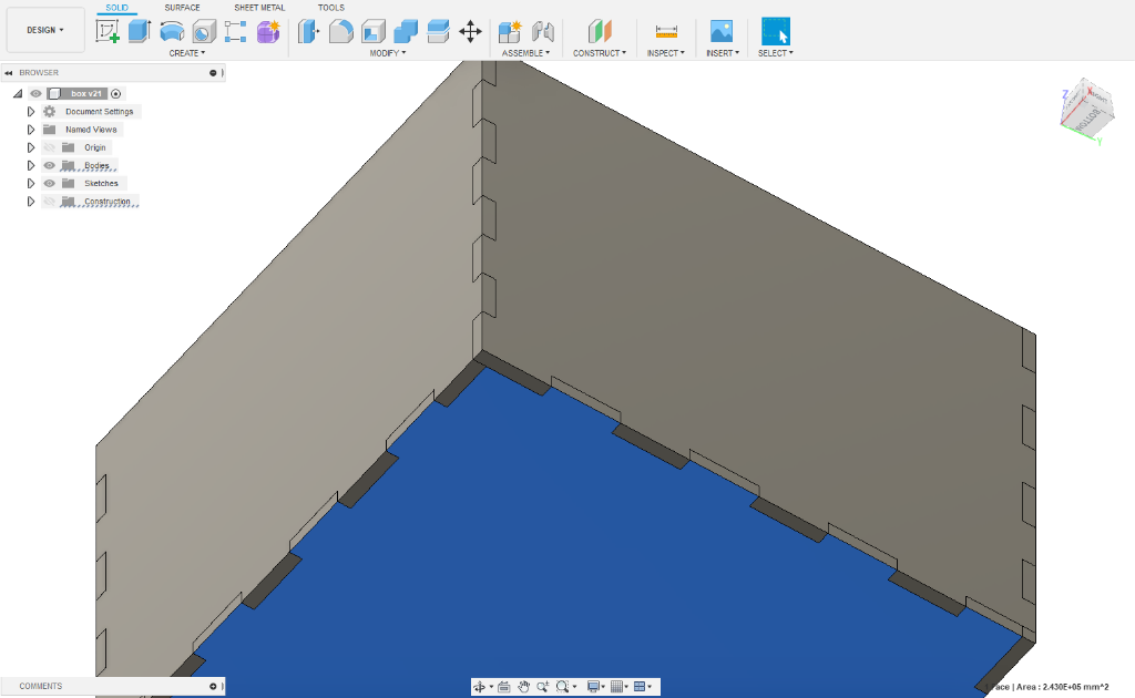
The size of the box is 500 x 350 x 510mm. The front door is not attached, as I will add hinges on the finished product.
On the inside of the box, supports allow an axis to be placed, onto which the filament spools will he hung. This support will be machined and inserted onto a carved hole.

Every piece of the design is layed out flat to prepare for the next step. I found that the most convenient way to do this is to copy the bodies into a new component, then to use some align and move operations to place the parts in the right places.
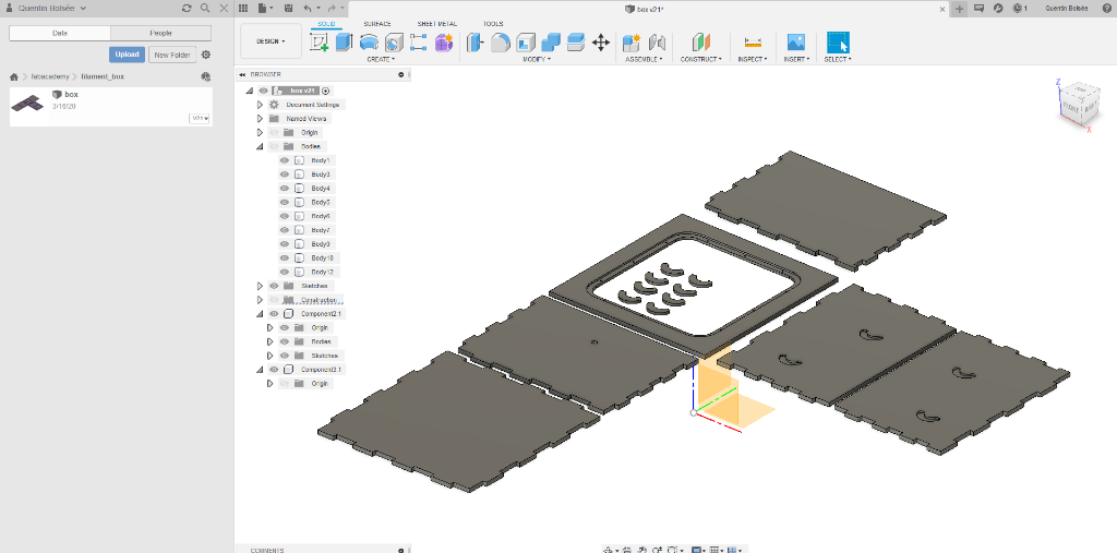
Drawing rectangles the size of my wood sheet allows me to separate the work in several independent jobs. The size of a sheet is 610x1220mm.
I will be using the following settings for the CNC:
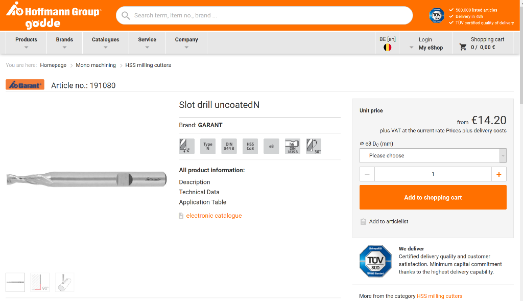
- 6mm flat end mill with 2 teeth
- 0.1mm chip size
- 9000rpm
- 1.5mm maximal stepdown
One of the most delicate part of the machining is the clearing of the window. With a stepdown of 1.5mm, this is one of the most time consuming operations.
![]()
To mill the side of all parts, I use a 2D contour operation. It is important to always check that mulitple depth is enabled, otherwise the stepdown setting will be ignored and the contour will be done in a single pass, which could break the tool.
On the contour operations, I also add tabs to make sure the part doesn’t fly off during the last contour.
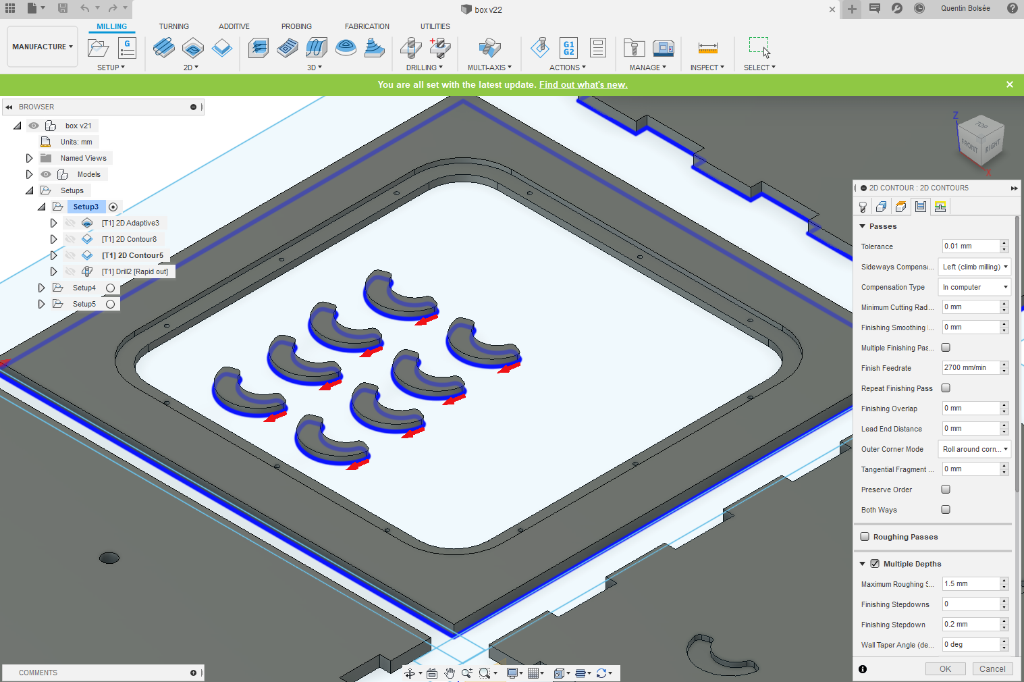
Finally, the corners are drilled through, to avoid the round corners that the 6mm tool will inevitably create.
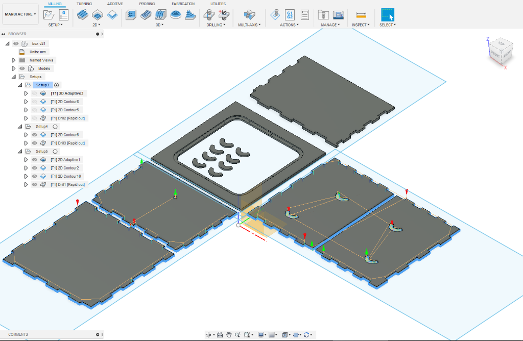
The same logic is applied on the two other sheets, making a total of 3 jobs that need to be exported individually.
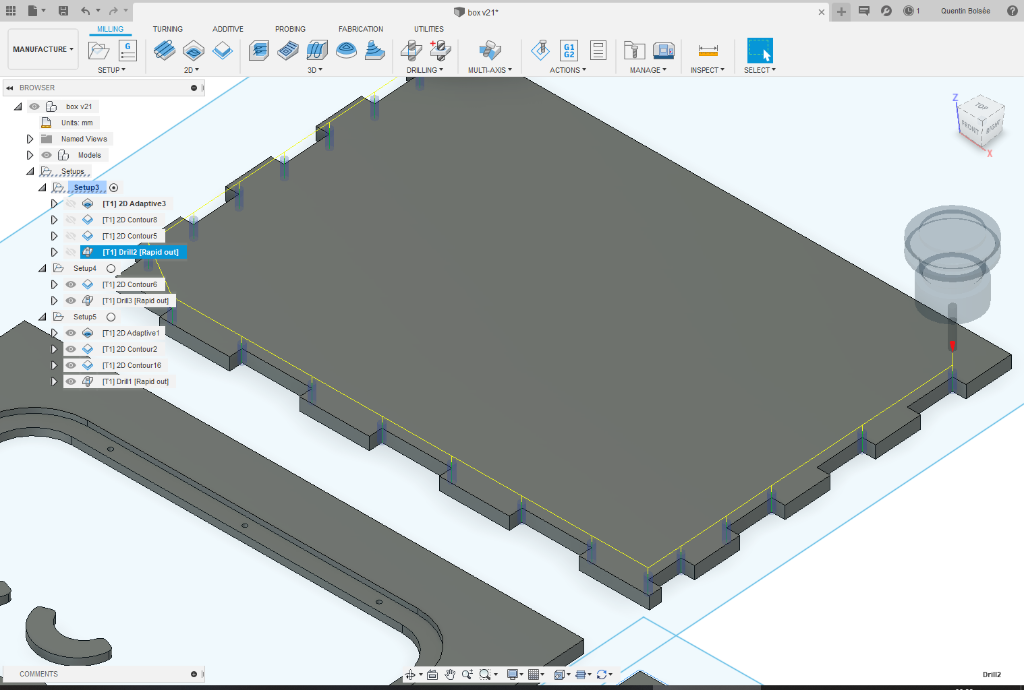
A job is exported with the postprocess option that appears after a right click on a given setup. It is important to select the right type of configuration for your CNC.
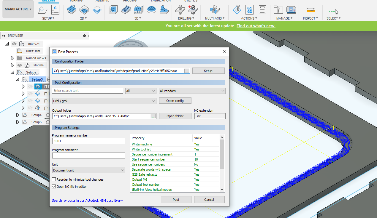
Cutting
Before starting the work, I make sure the tool parameters are consistent with the ones I used in Fusion 360.
After producing the .nc file, I import it in the controller software for our CNC machine. The toolpaths are visible in a 3D viewer, and the current position of the mill is shown as well.
It’s important to use the G54 coordinate system, which means we are working in the wood stock coordinates. In this system, the XYZ origin is a point at the top of the stock. For the XY axes, I simply move the machine near the bottom left corner of the stock. For the Z component, I manually lower the mill until it barely touches the top of my wood sheet. I then set the zero to the current coordinates in the G54 mode.

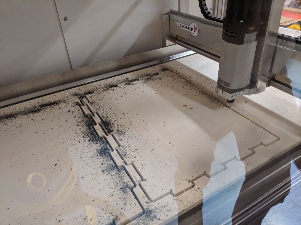
Milling generated a lot of chips because we don’t have an air pump connected to the tool head. However, this didn’t seem to affect the quality of the cut too much.

In some cases, the tool reaches the protective MDF layer underneath, creating some black dust.
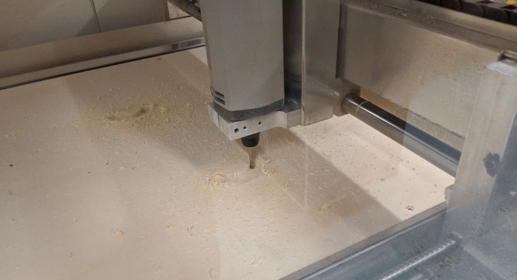
When a cut is complete, you can see the drilled holes on every inside corner. This was the last operation to be performed in each case.

The groove came out nicely and required minimal cleaning.

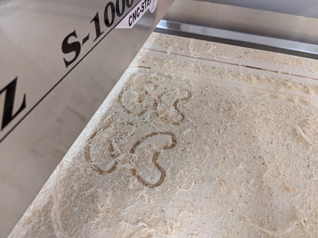
The last part I milled was the side walls of the box, where there is an insert to hold the spools.
The wooden piece I will insert there came out a bit rough, and will need some cleaning to fit.
Building
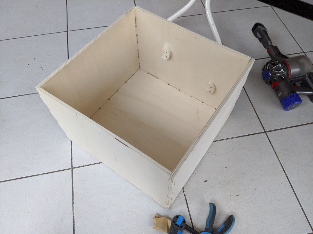
I start by laying the components flat to make sure everything is fine and it all fits together.
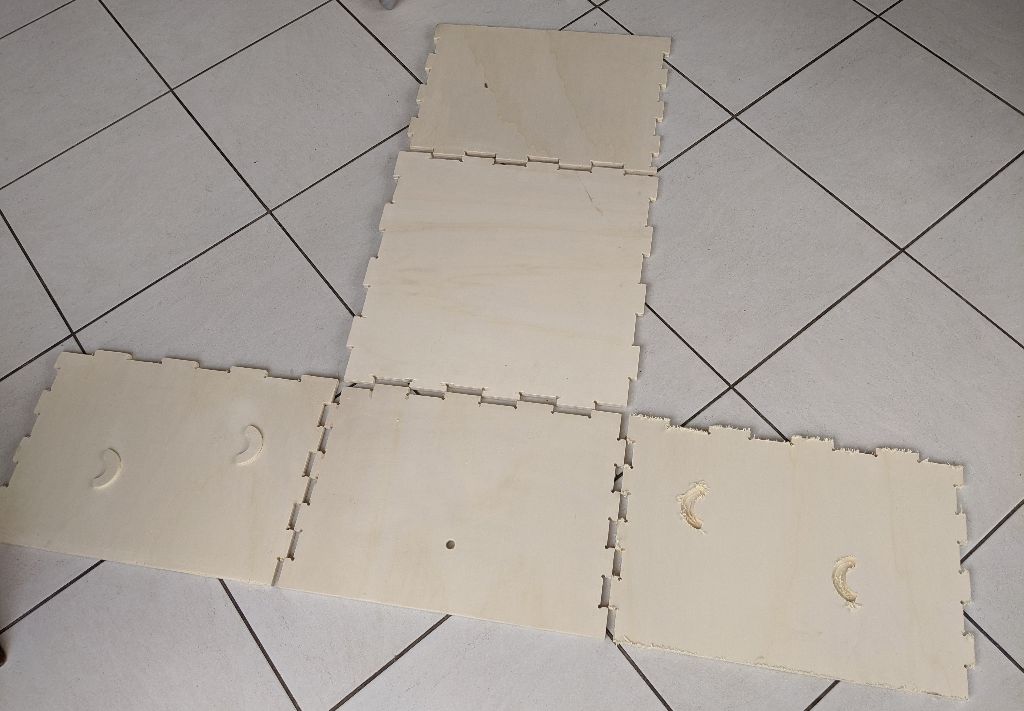
I had to clean out many of the parts with some sandpaper. Only one grit size is needed, as wood is naturally rough on the surface.
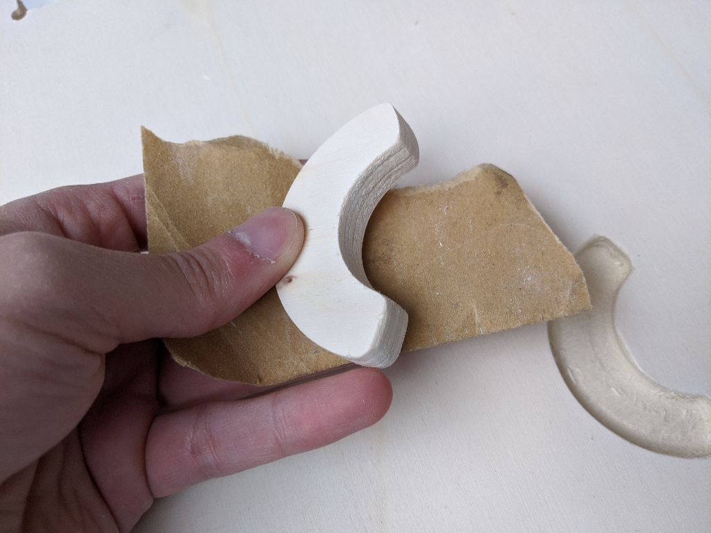
The insert wouldn’t fit without adding some force.
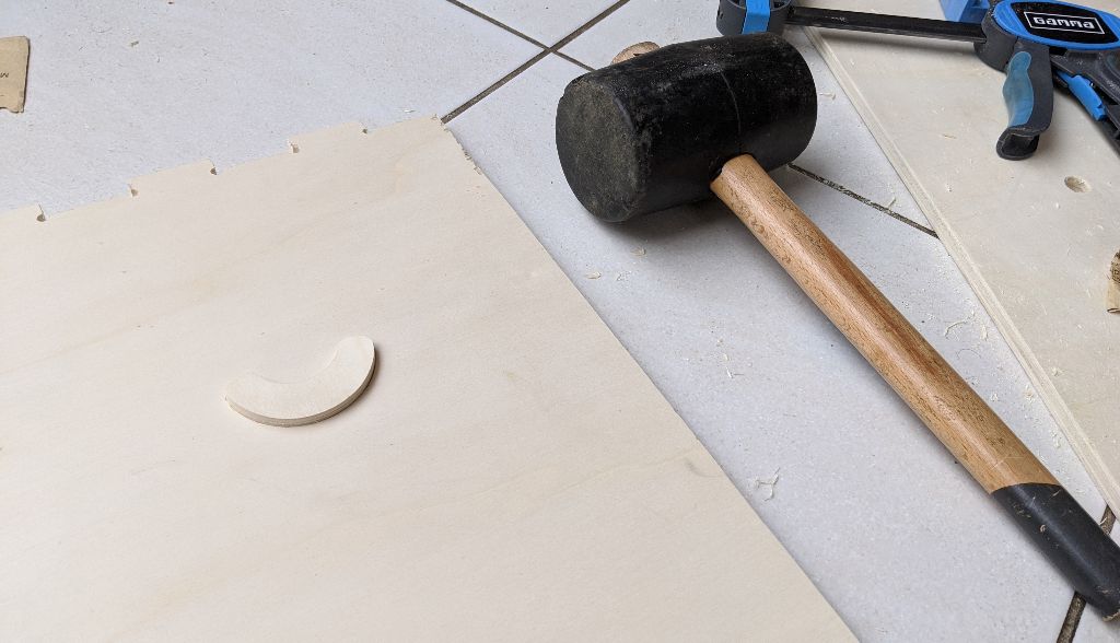
I add a second insert on top of the one that is press fit. This is a bit of an afterthought, so I have to drill holes manually
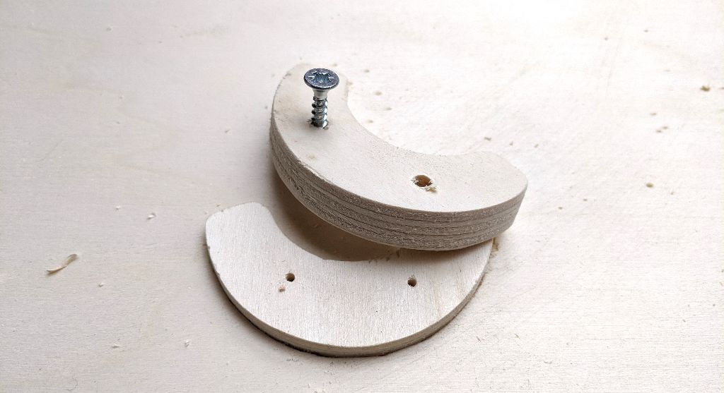
The additional length will help support the spool in a better way.

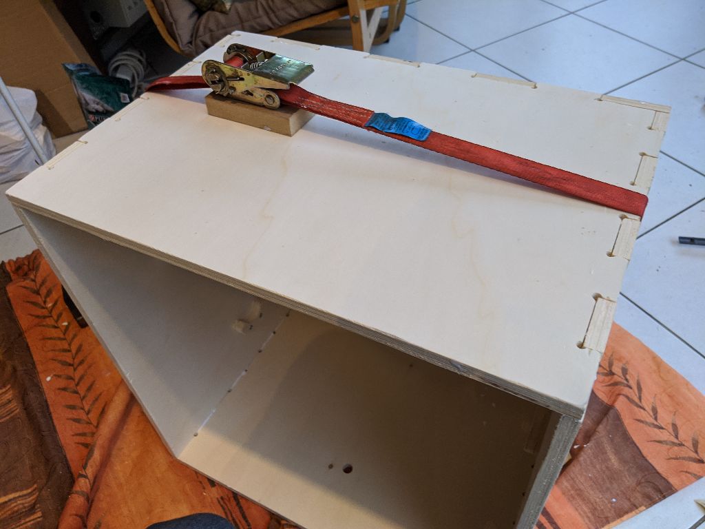
For the assembly, I use some regular wooden glue. It takes some time before it dries, but I still have to be quick in assembling all the components.
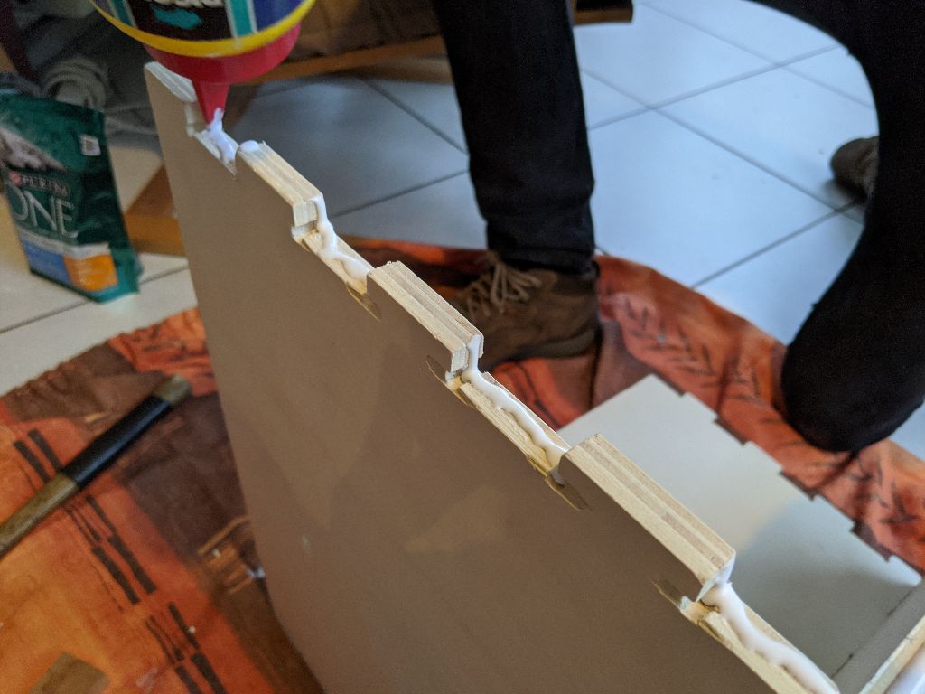
The box seems to fit together nicely, although some sanding was needed on the box joints.
Adding pressure is essential during drying; this ensures most of the sides are flush against each other so that the glue can be effective.
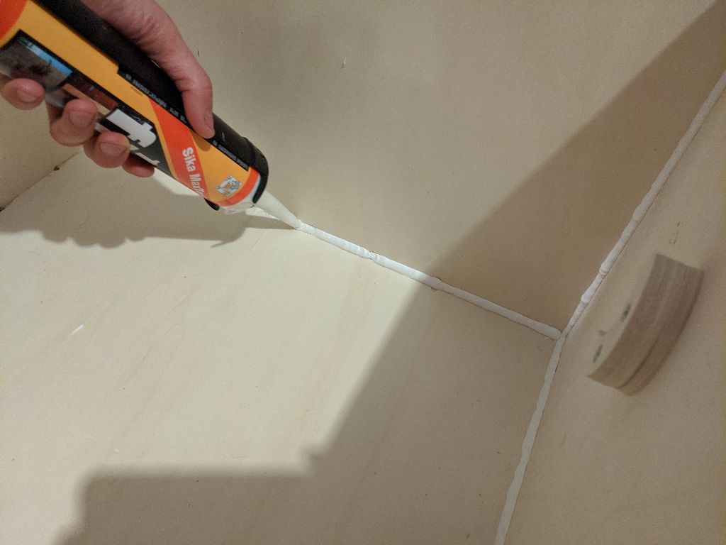
I wanted the box to be airtight, so I add some silicon joint on the inside edges.
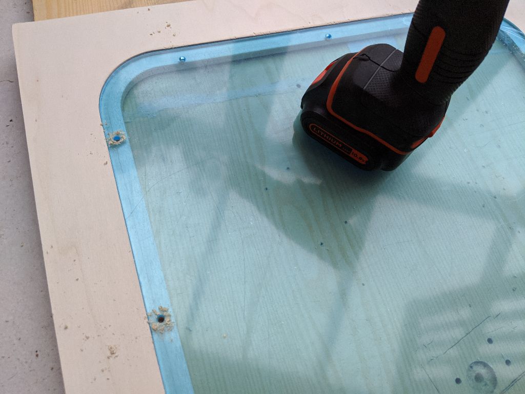
While the rest of the build is drying, I attach the lasercut PMMA window to the front panel.
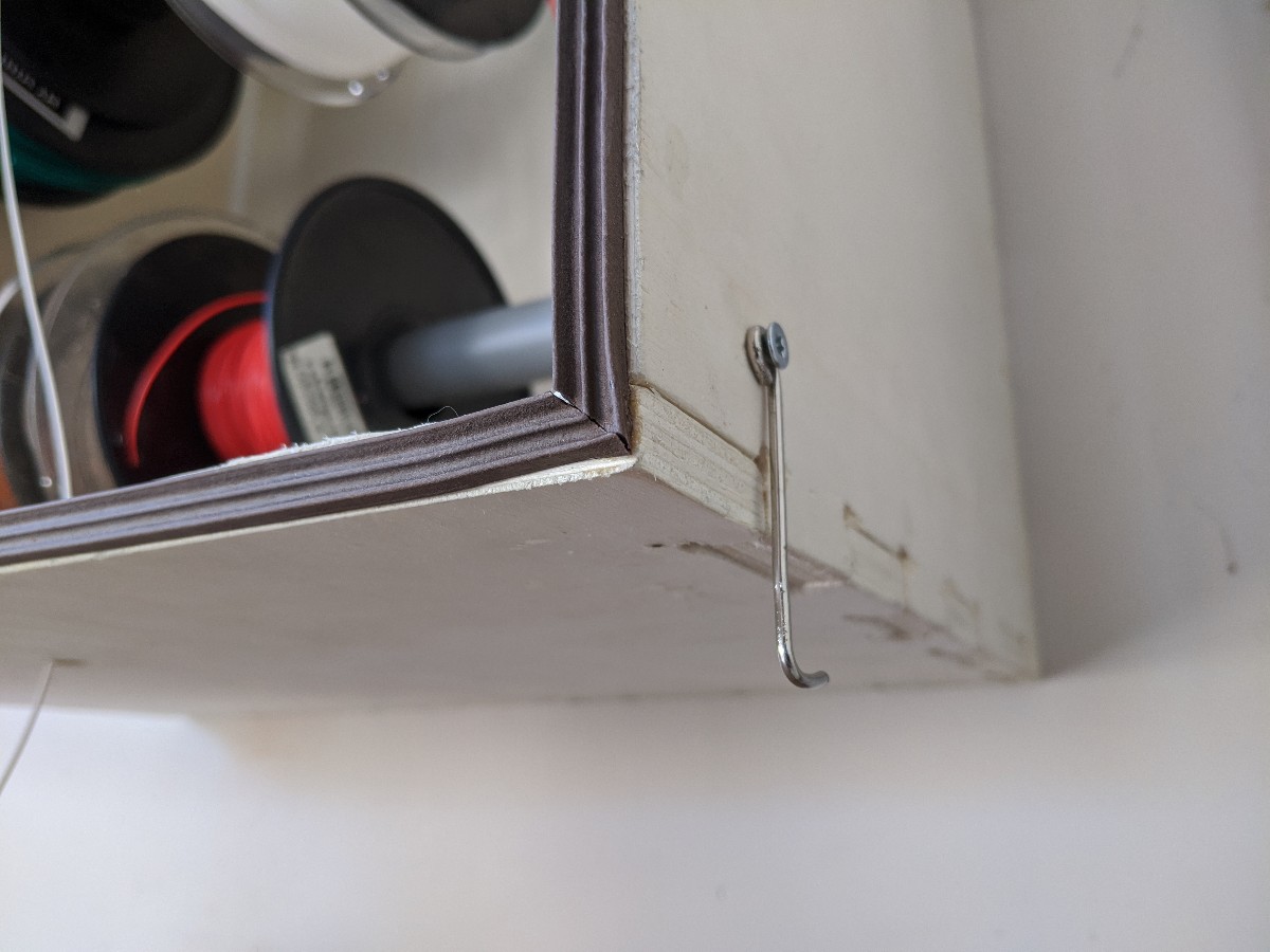
I add a hook and a joint on the front of the box to make sure the front face will be airtight as well.
The spools sit onto a 40mm pipe.
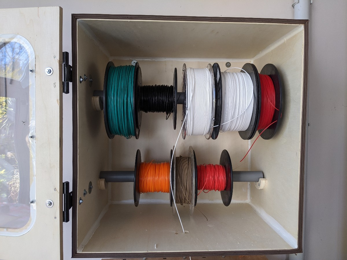
The finished product seems to work nicely! I still have to add some sort of rubber valve on the bottom face to keep the box airtight, but this can still be done later.