3. Computer Aided design
Computer aided design (CAD) encompasses a wide range of methods and softwares, including 2D and 3D design, but also more abstract ideas such as schematics and diagrams. While the target of CAD is often physical objects, the level of abstraction proposed by most of these tools allows us to explore impossible-to-make geometries, and whole new types of generative/parametric design.
Research
For the purpose of this week’s assignment, I will focus on 3 methods. The first is 2D drawing, for which I will mix vector art and rasterization in both Inkscape and Adobe Photoshop. Next, I will show basic parametric 3D design in Fusion 360, which I export as a mesh file. The resulting mesh is finally imported in Blender in order to create a realistic rendering of the project using ray-tracing. I will also briefly explain how to use Blender to create objects using only vertices and modifiers.
When designing 3D data, the CAD softwares can generally be divided in 2 main categories:
- Mesh-based: any 3D object is represented as a set of vertices connected by edges and faces. This format in used in video-games and can represent any geometry if the triangle count is sufficiently high. Manipulating these triangles can be achieved with a set of helping tools and/or transformations.
- Parametric design: here, 3D shapes are seen as functions of the 3D space, produced by a set of formulas. For instance, a zero-centered cirlce of radius r can be described by the equation x²+y²=r². Intersecting several curves and generating 3D volumes through simple rules allows the user to create (almost) any type of shape, and also enables backtracking: the dimension of a given curve can be modified at any time, affecting the whole history of the 3D shape.
For instance, Blender is a mesh-based approach, while Fusion 360 is a parametric design tool. However, they are not mutually exclusive, as will be shown later.
2D graphics: Inkscape and Photoshop
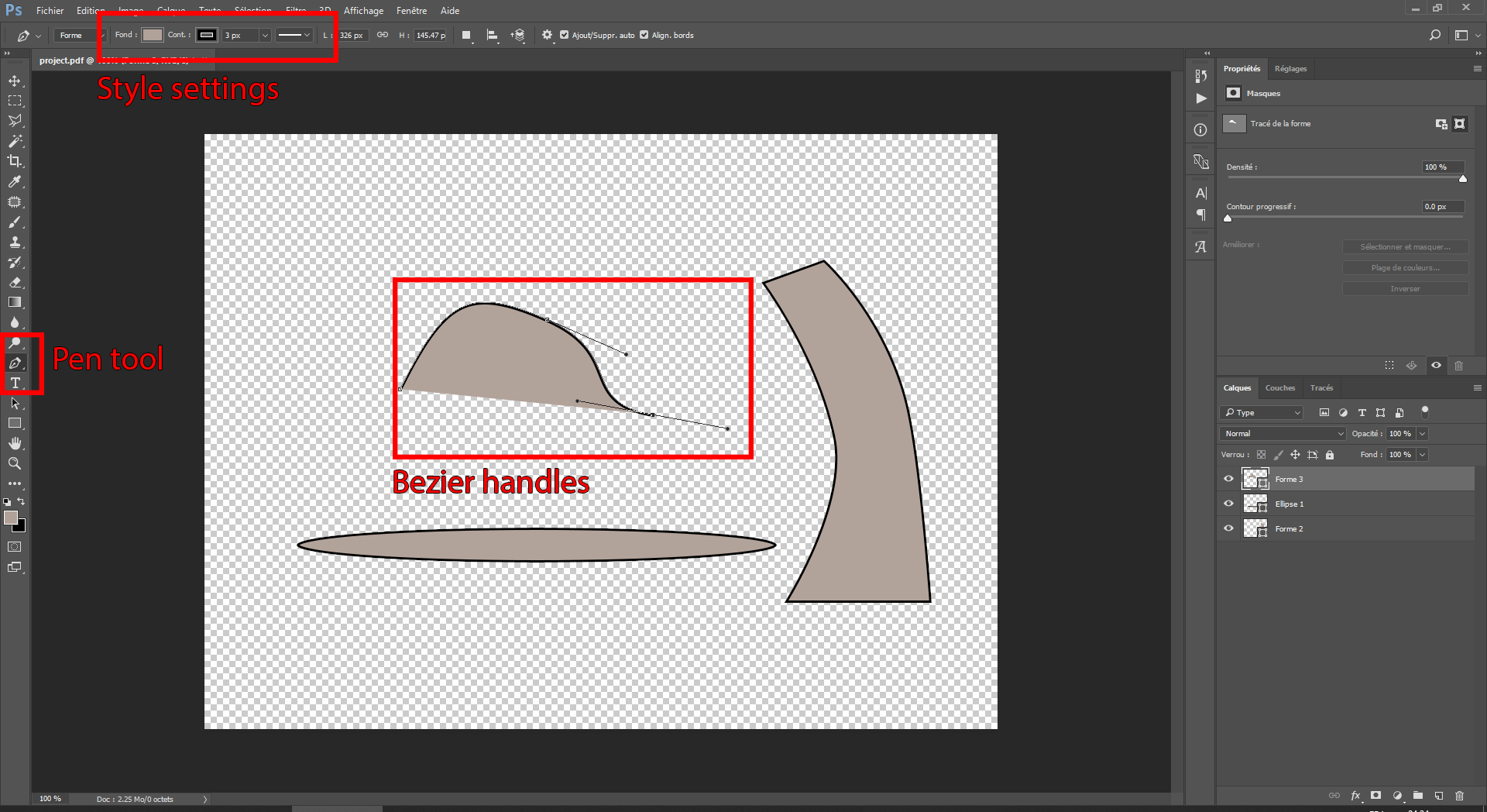
Photoshop is a powerful tool for image processing, which can handle both raster graphics and vectors. In this example, I start by creating a simple bezier curve using the pen tool and clic+dragging the mouse to control the bezier handles. Various styles can be applied on a curve, including the outline and filling colors.
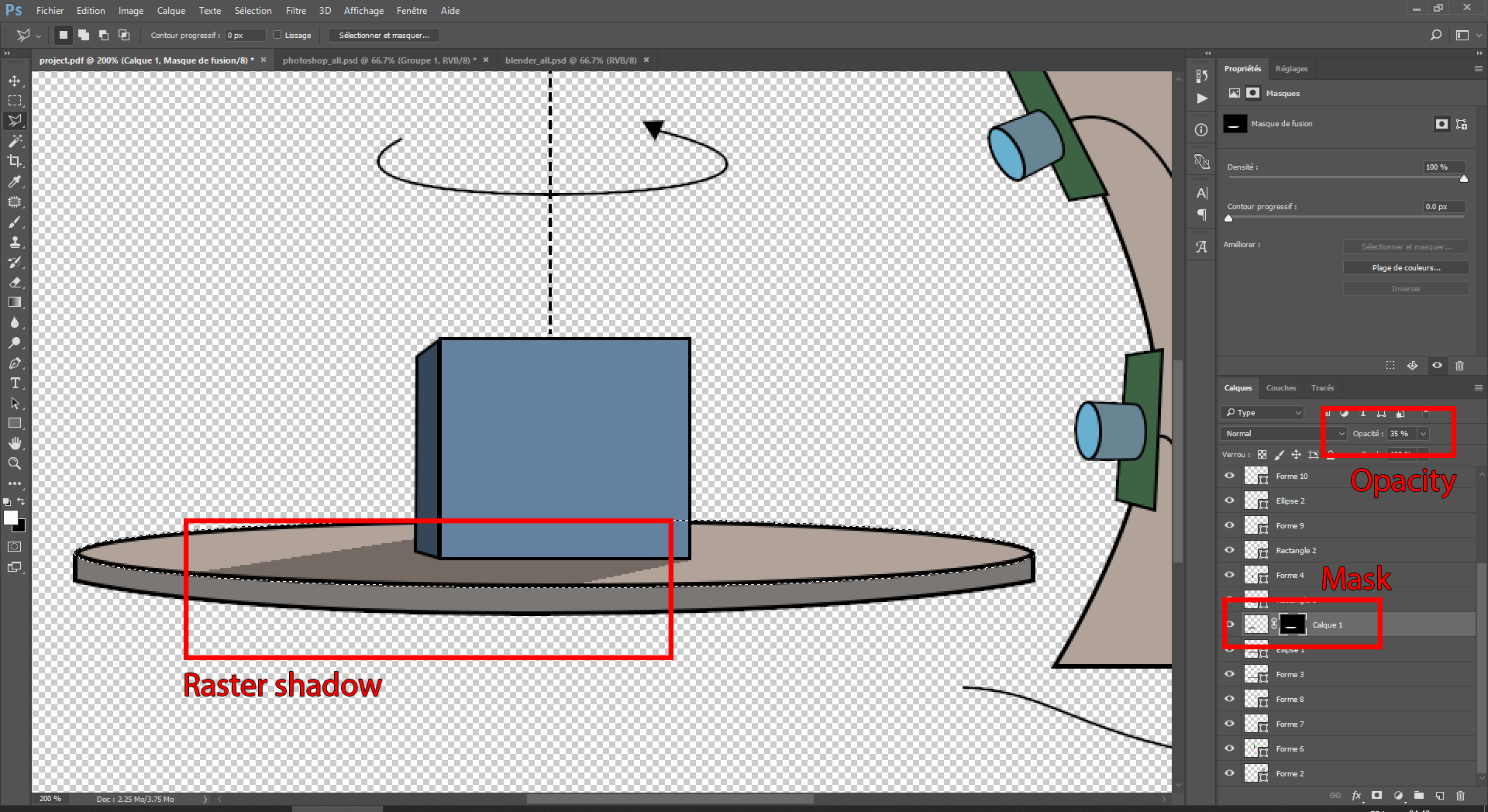
Once I drew the basic components of my project, I decided to add a shadow effect. While this could be achieved easily with vectors, I want to showcase raster pixels with a powerful feature: the alpha channel. I start by filling a large portion of the image with a constant black color, then I create an alpha channel, which enables transparency effects. This allows me to hide the part of the shadow that does not fall onto the circular plate by simply setting their alpha to 0. The alpha channel is a grayscale image in which white pixels indicate an 100% opaque pixel, while black indicates full transparency.
Once I am happy with the result, I save the file to a .pdf format and load it in inkscape. By doing so, I preserve the vector format. I then add missing details using the equivalent of Photoshop’s pen tool.
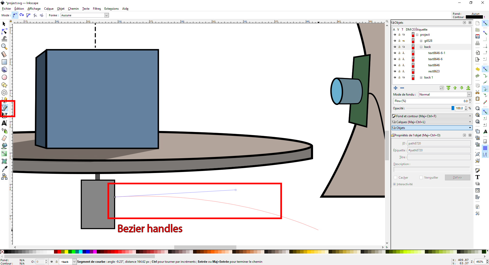
After adding some explanatory text and saving the result to a .svg file, I can easily embed it into this webpage without loss of quality:

3D parametric design: Fusion 360
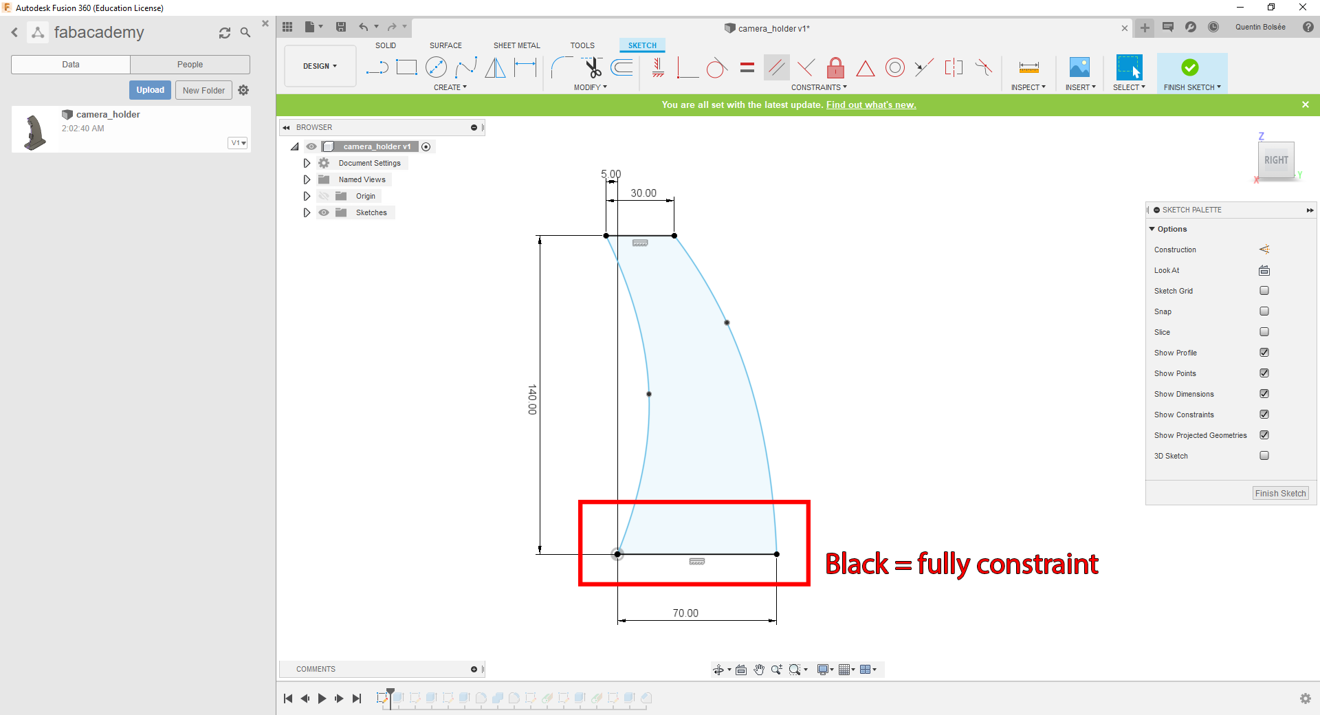
Fusion 360 is an excellent parametric design software, including many additional tools for simulating and manufacturing parts. At its core, it operates like any other parametric CAD software (e.g. FreeCAD, CATIA, Solidworks, …). I start by drawing a simple shape with Bezier curves and straight lines to reproduce the camera holder from my 2D design. I manually fix the dimension of the line segments, to get a sense of scale of my final object. In a robust project, no dimenion should be left floating, but in this case I leave the Bezier curves floating as they are mostly for illustration purposes.
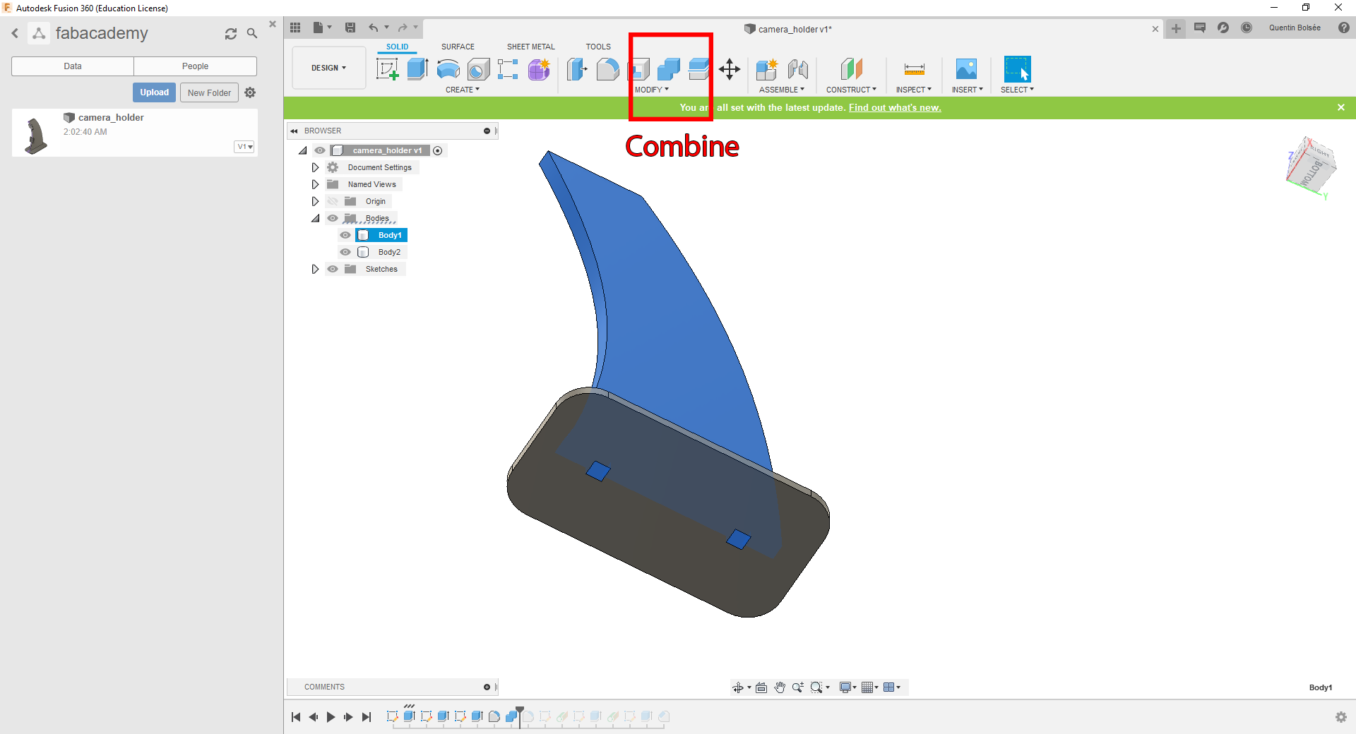
I add a bottom plate to my camera holder by drawing a rectangle on the XY plane. The two parts could be held together using simple indentation marks, so I add some on the upper part, then use the Combine tool to subtract the excess material in the bottom plate.
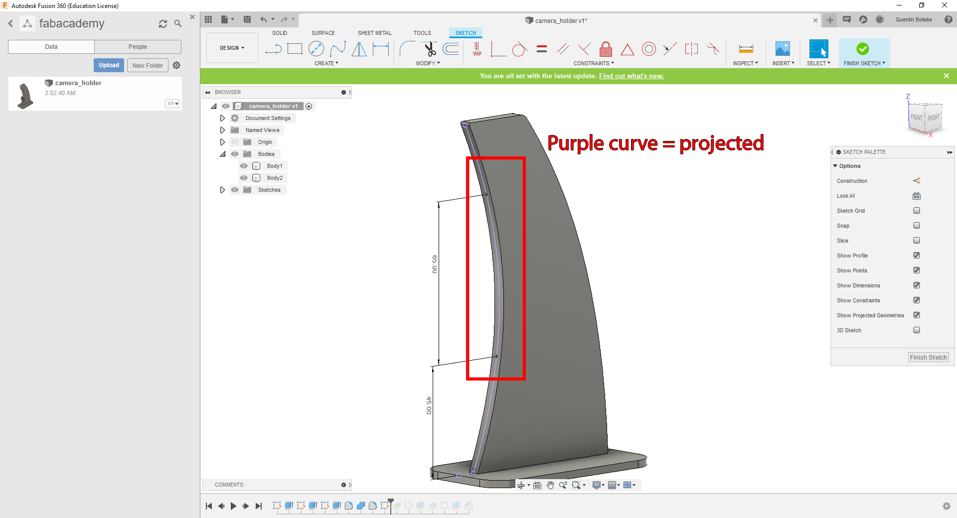
The next step is to add plates for holding the cameras. I make use of the Project tool, allowing me to project a curve from an existing shape into a new 2D drawing. I can then add new features onto this existing curve, in this case two points marking the position of the cameras.
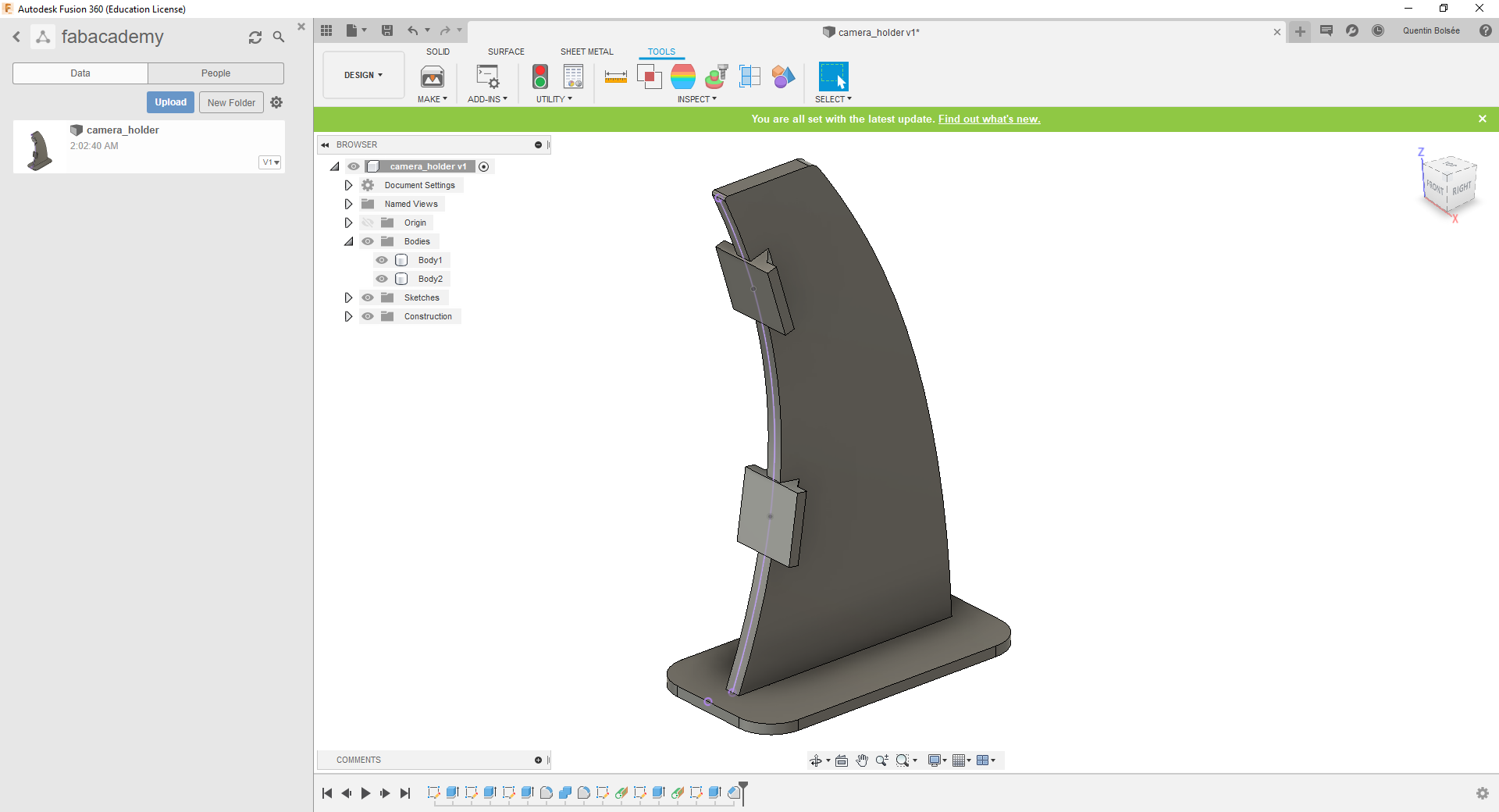
After building some geometry onto these marked positions, I get a finished result.
3D modeling and rendering: Blender
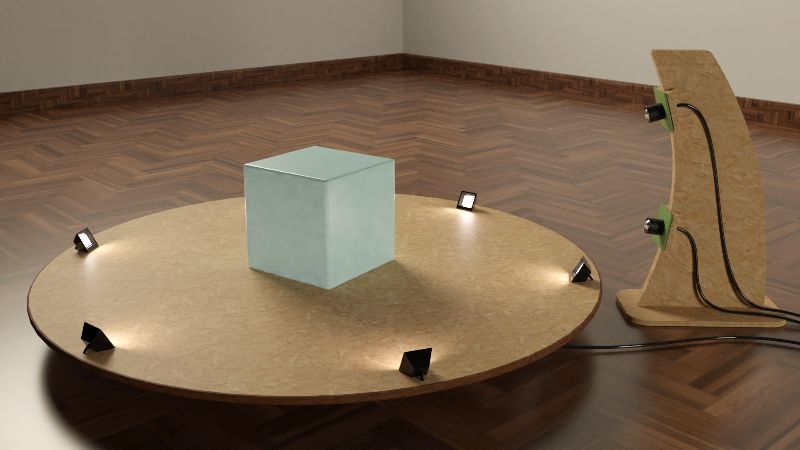
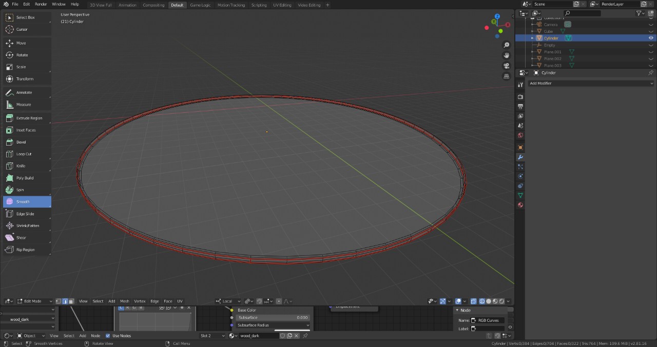
Blender is an extremely versatile 3D modeling and rendering tool. It also holds other great features such as video-editing, and a fully-functional game engine. We will here show how to create a realistic rendering of our project using the Cycles engine. I start by adding the missing geometry of the project, such as the circular plate. This is easily done by adding a cylinder object of the right dimensions. I also add a small bevel effect to the edge (ctrl+b) to remove the sharp edges, giving a more convincing look during rendering.
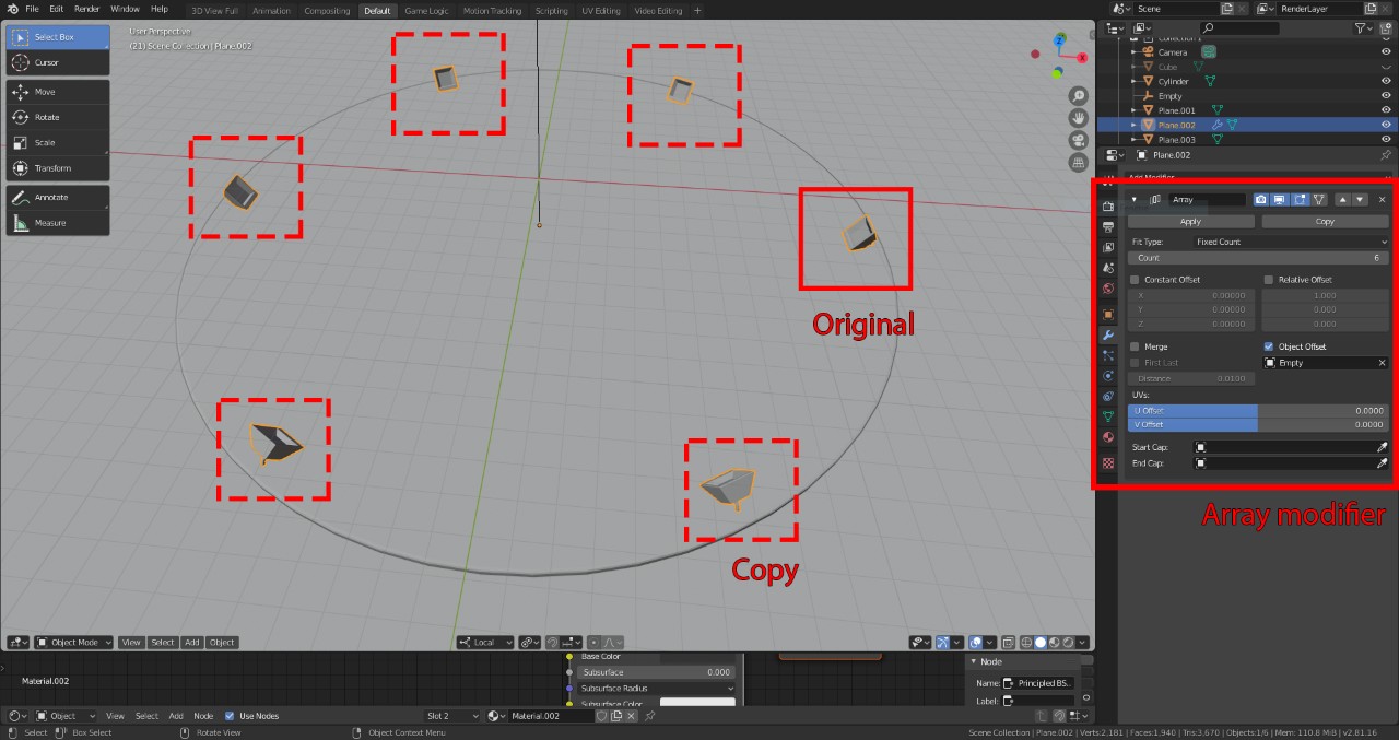
In my project proposal, the object being 3D scanned is being lit up by a set of LED lights attached to the circular plate. I can make use of Blender’s modifier tools by drawing a single LED, and creating 6 copies of it using the array modifier.
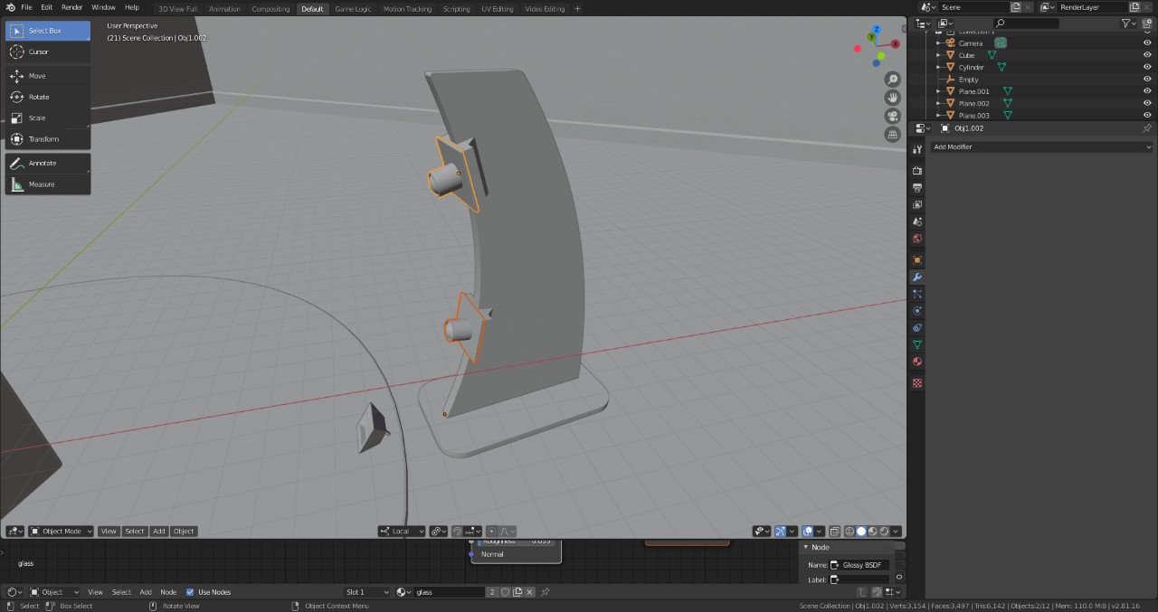
After adding some walls to the scene, I import the 3D object from Fusion 360, which was exported in the .stl format. I also draw some mockup raspberry pi cameras attached to it.
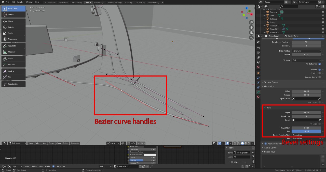
To simulate the wires present in my 2D drawing, I use 3D Bezier curves from Blender. In this case, the handles can be moved in full 3D instead of being restricted to 2D. By default, there is no width to a Blender Bezier curve, but this can be obtained by setting the Bevel option to a non-zero value.
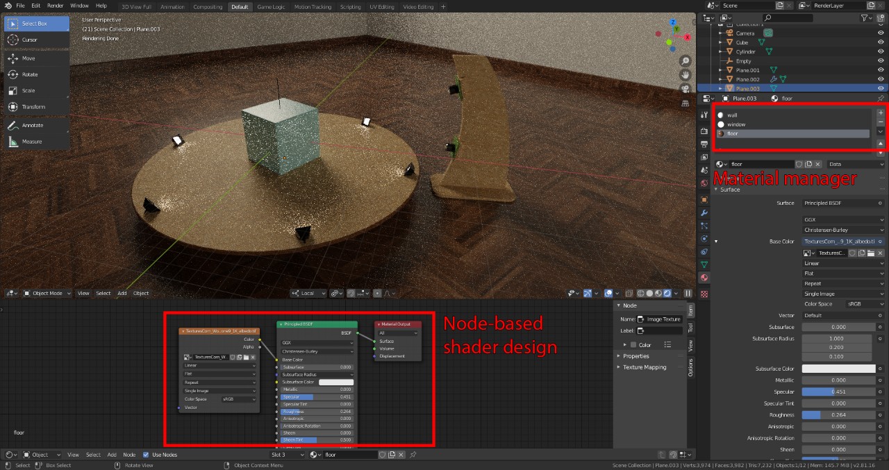
For a convincing ray-tracing rendering of the scene, I have to assign a material to every object in the scene. A single object can also include multiple materials, assigned on a per-triangle basis using the buttons next to the material’s name. The floor and most parts of the object get their color from an image texture downloaded from the web. This is can be done via the node shader editor.
After adding some lighting panels with an emitter material type, Blender’s Cycles ray-tracing engine can simulate convincing light bounces throughout the scene, creating soft shadows, diffusion and reflections effects. To save on rendering time, Denoising is applied on a rough version of the ray-traced render (1024 samples per pixel).