Urumbu 3D printed linear axis
This project provides a fully printed linear motion rail, with minimal bill of material.
Motion demo:
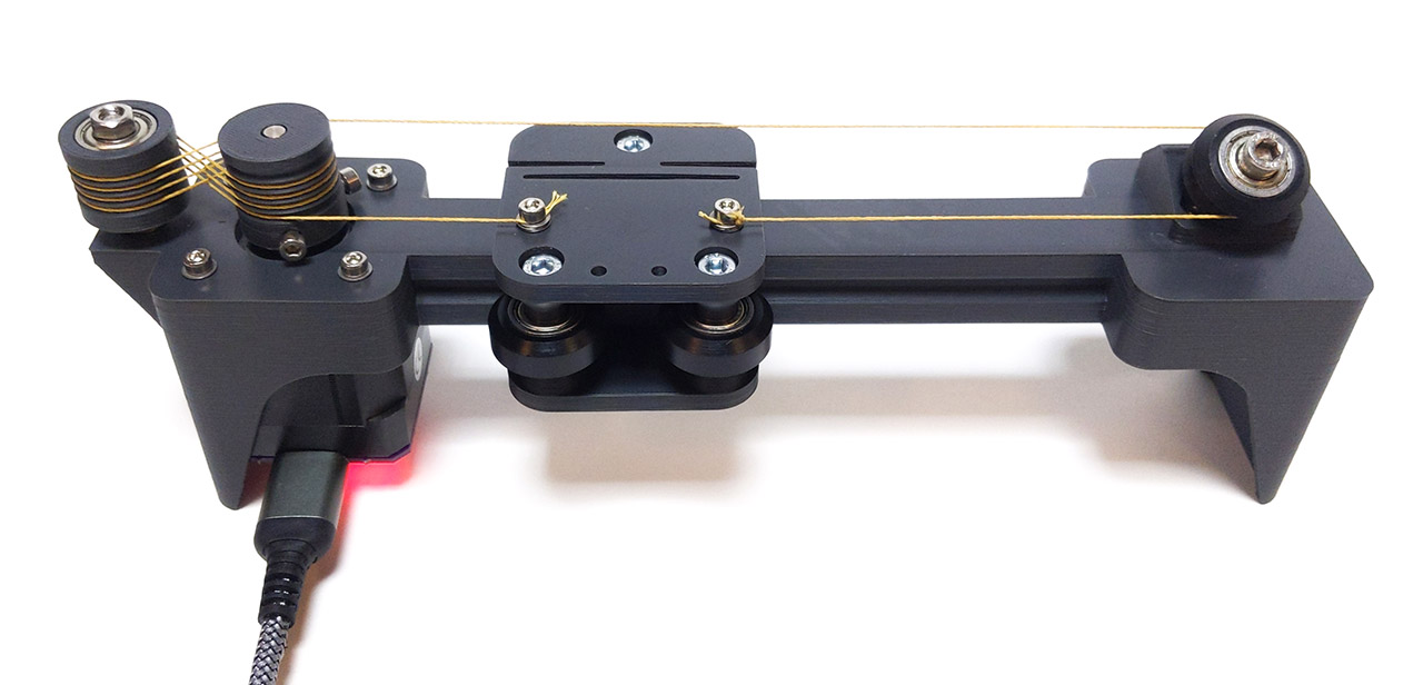
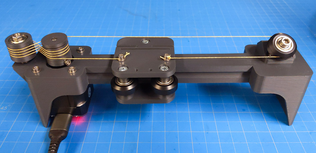
Completed axis:
Design
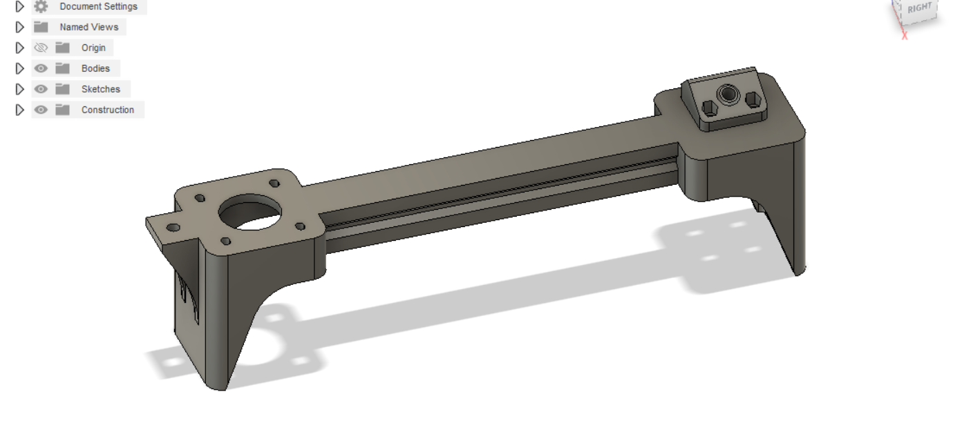
The design was made in Fusion 360. The length of the rail is parametric. The dimensions match that of a 20mm aluminum extrusion, so it would be simple to adapt the design towards aluminum extrusion with 3D printed add-ons.
Printing
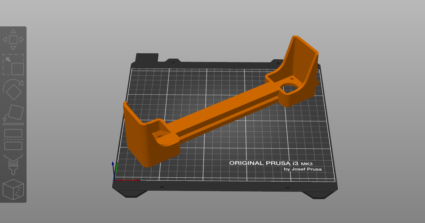
All prints are achieved on a Prusa i3 MK3 with 0.2mm layer height.
The axis is printed first, it has to be placed diagonally to fit the print bed:
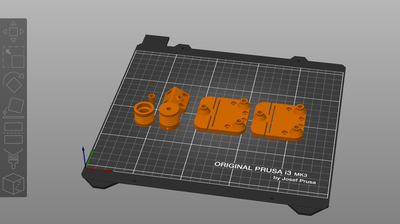
Then all other accessories are printed together:
Assembly
The pulley is mounting at an angle to accomodate for the height difference of the string. For this purpose, a special part is mounted with M3 bolts.
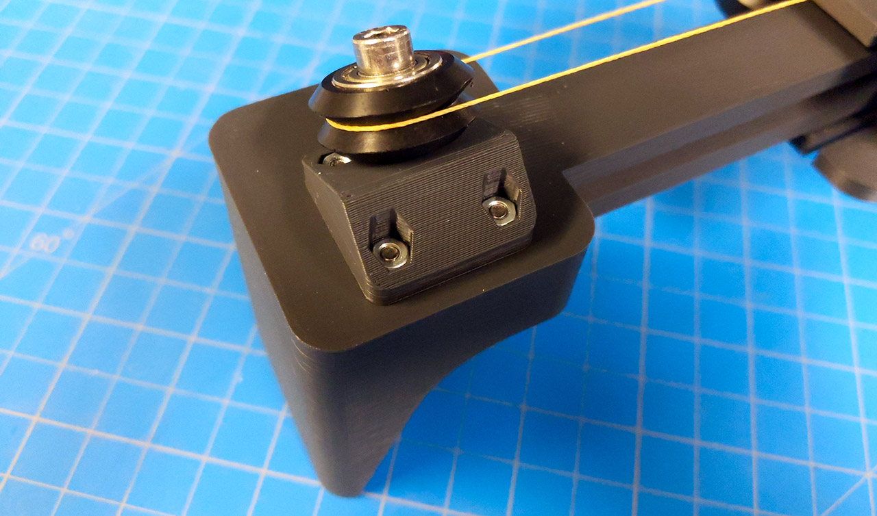
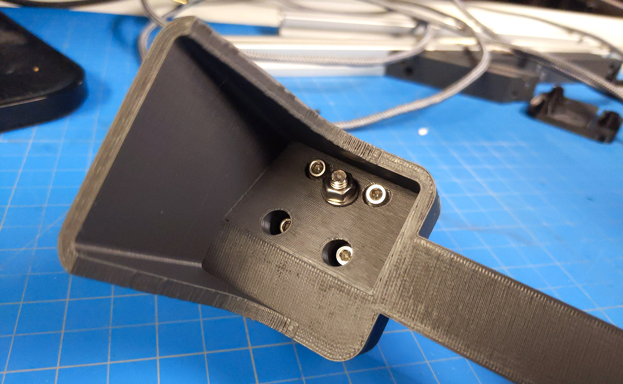
Bottom:
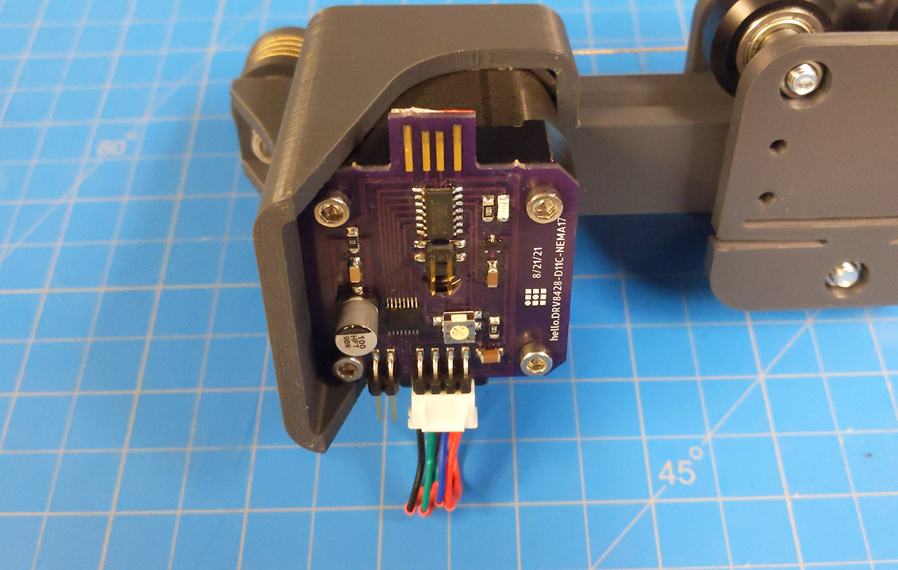
The NEMA 17 motor is similarly mounted with M3 machine screws, and the Urumbu stepper module is mounted on its back:
The capstans are then added. Note that the height of both can be adjusted, but their top faces should be at the same height. Inside of the capstan pulley (left), two bearings are inserted with a spacer in-between to prevent axial compression when tightening the bolt:
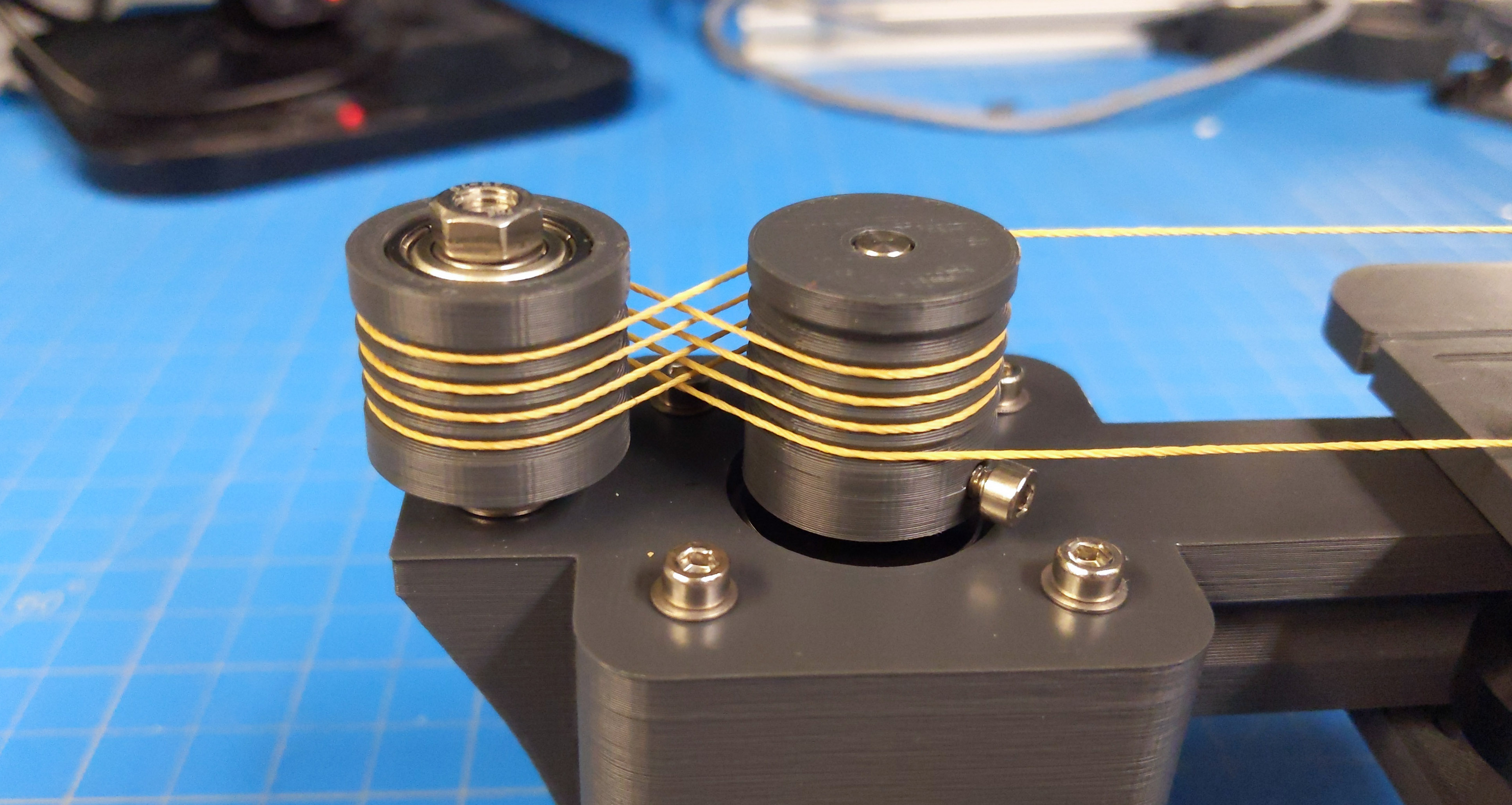
Here is the complete axis, with M5 bolts and delrin wheels on the carriage. Note the two M3 matchin screws holding the kevlar string.
Bill of Material
Screws:
- 12 M3x8mm
- 4 M5x30mm
- 1 M5x40mm
- 8 M3 nuts
- 5 M5 nuts
Bearings:
- 3 delrin wheels
- 1 delrin pulley
- 2 bearings
String:
- 1m kevlar string, 0.5mm thick
Electronics:
- 1 NEMA17
- 1 Urumbu stepper board
- 1 USB extension cable
Downloads
.stl files
Fusion archives
STEP files
License
This project is provided under the MIT License.