SVG PCB splines
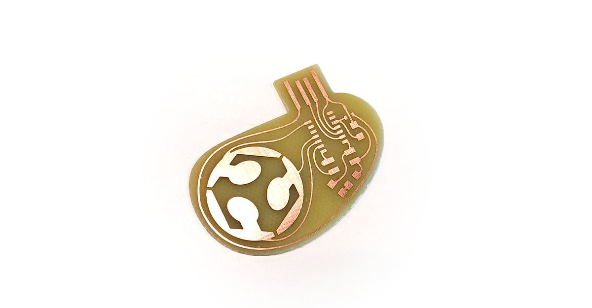
Design
This board was entirely designed in SVG PCB to demonstrate:
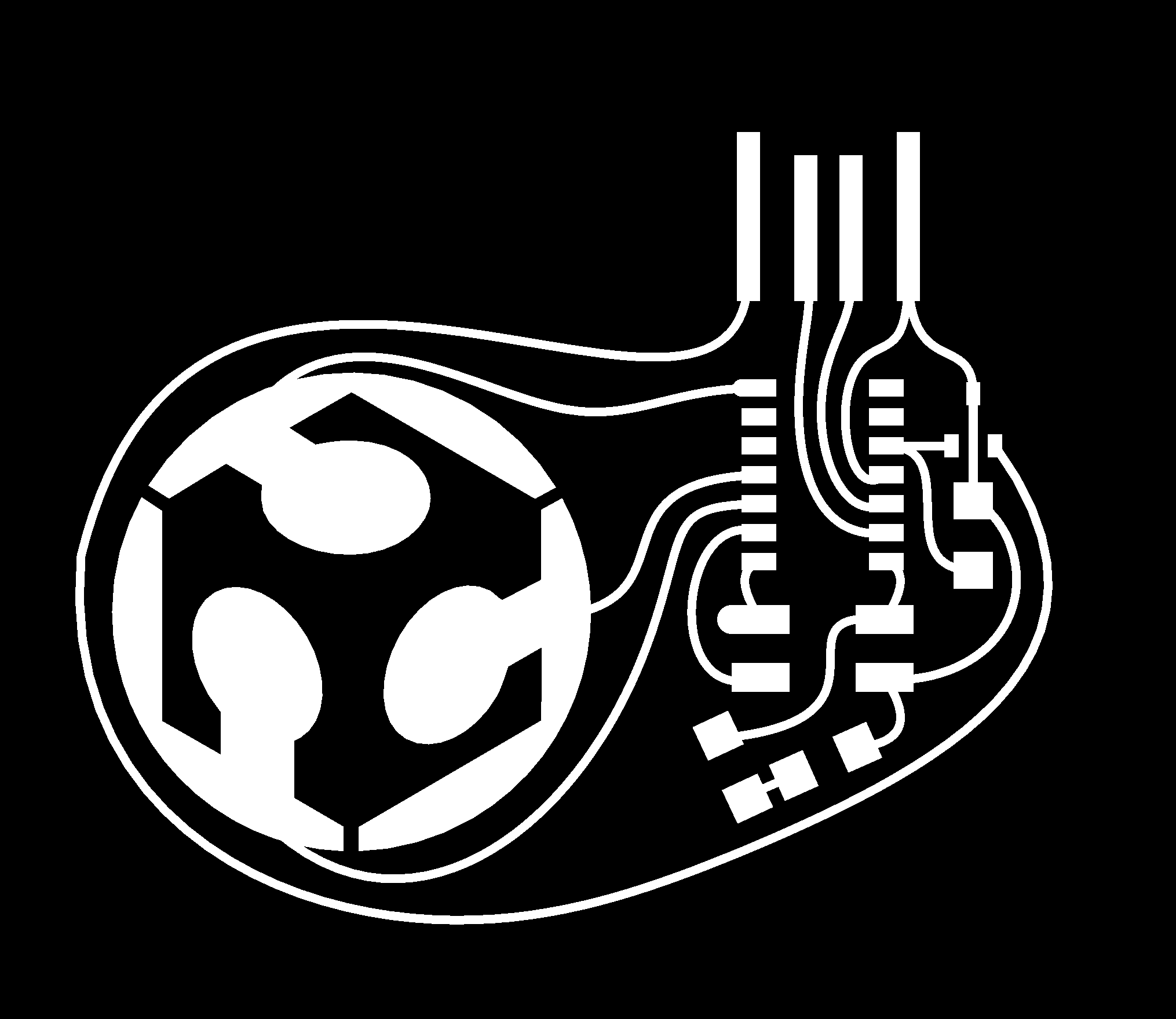
- Native svg insertion: the FabLab logo’s path data was simply copy/pasted to make a new footprint.
- Spline wires: a new type of wire that creates a spline of degree N from a list of points.
- Capacitive touch: the PTC peripheral included in the SAMD11 is a great demo for step response touch sensing, with no additional hardware.
Click on this image to try it out for yourself!
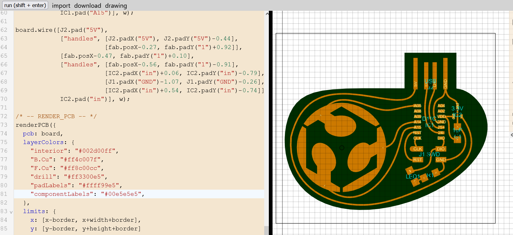
The produced svg file can be processed with mods to produce milling paths. You can also download the png files rendered at 1000 DPI at the bottom of this page.
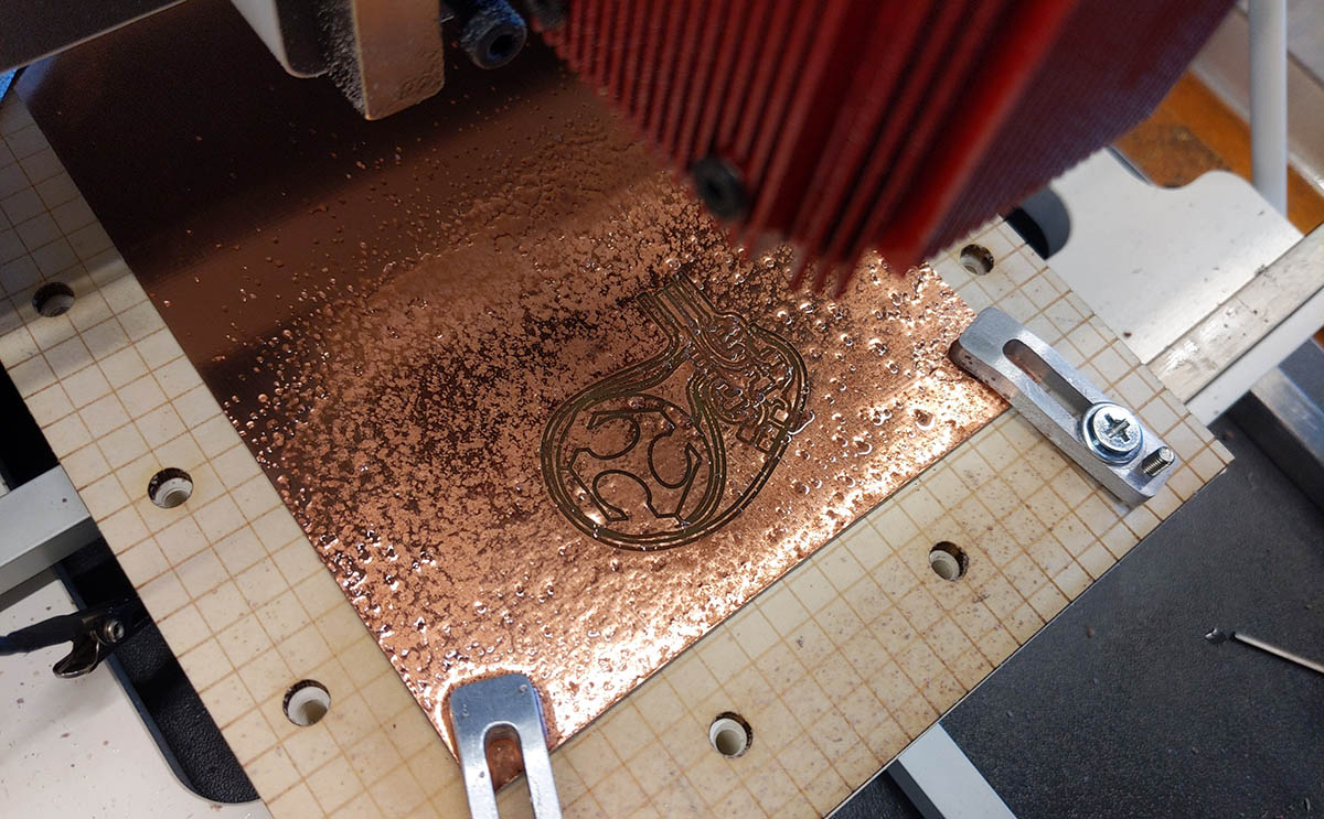
Production
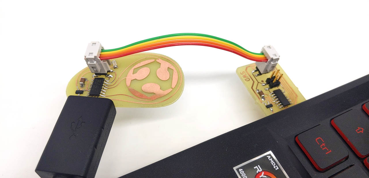
The board was milled with a Wegstr CNC with a 45° mill for trace isolation, followed by a 0.6mm flat end for copper clearance and a 1mm edge cut. We managed to mill it in FR4 with no issues, note the copious amount of mineral oil to help lubricate the tool.
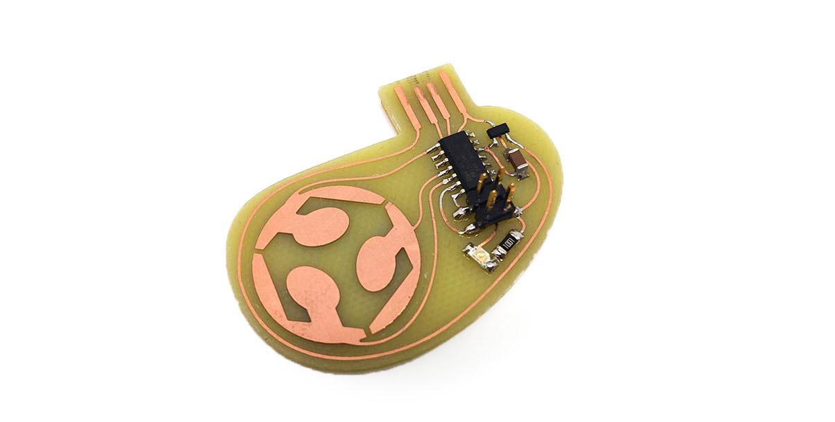
The milled board was funny looking with all the squiggly traces:
The components are easily soldered.
Programming
You can easily flash the SAM BA bootloader with our SWD programmer. After this, the board can be programmed through Arduino through the Fab SAM core.
Code
Patching Adafruit’s Freetouch
To enable and use the PTC peripheral, there are two options:
- The official QTouch library in Atmel Studio.
- Adafruit’s FreeTouch, a 100% open source alternative.
To demonstrate Programming through the Arduino IDE with the Fab SAM core, I picked Freetouch. The other benefit is its compact flash size, as we only have 16 kb to work with. The official Adafruit Freetouch only supports SAMD21, so I forked my own version and added register info for SAMD11. Everything else worked beautifully out of the box:
#include "Adafruit_FreeTouch.h"

[...]

Adafruit_FreeTouch qt(15, OVERSAMPLE_4, RESISTOR_50K, FREQ_MODE_NONE);

qt.begin();

[...]

int qt_value = qt.measure(); // read 10-bit value
To test this, I turn on the LED When the value is above a threshold (550 worked well in my case).

Keyboard
The SAMD11 has native USB support, this means that it can act as any USB device class. Notably, you can use it as a keyboard or mouse by enabling HID in USB config. Arduino’s Keyboard library can then be included in your code:
#include "Keyboard.h"

[...]

Keyboard.begin(); // done only once during setup

[...]

Keyboard.press(KEY_UP_ARROW); // press a key

[...]

Keyboard.release(KEY_UP_ARROW); // release key
When including Freetouch, there is very little flash space left, so I had to select the option “HID_ONLY” in USB config and give up on the serial port. Note that you can still double press on the RESET line (you’ll need to connect an external pull-down switch) to bring back the bootloader’s serial port if you want to reprogram it.
Video
Here is the board acting as keyboard arrows when pressed:
License
This project is provided under the MIT License.
Downloads
PNG files (1000 dpi)
Traces:
Interior:

SVG
220px
