Flexible capacitive sensor
This project is a collaboration with Jack Forman, aiming to explore two concepts:
- Bending a board with CNC-milled flexures
- Letting a signal pass through the flexure
It turns it works surprisingly well, and seems to be a good application for desktop PCB milling.
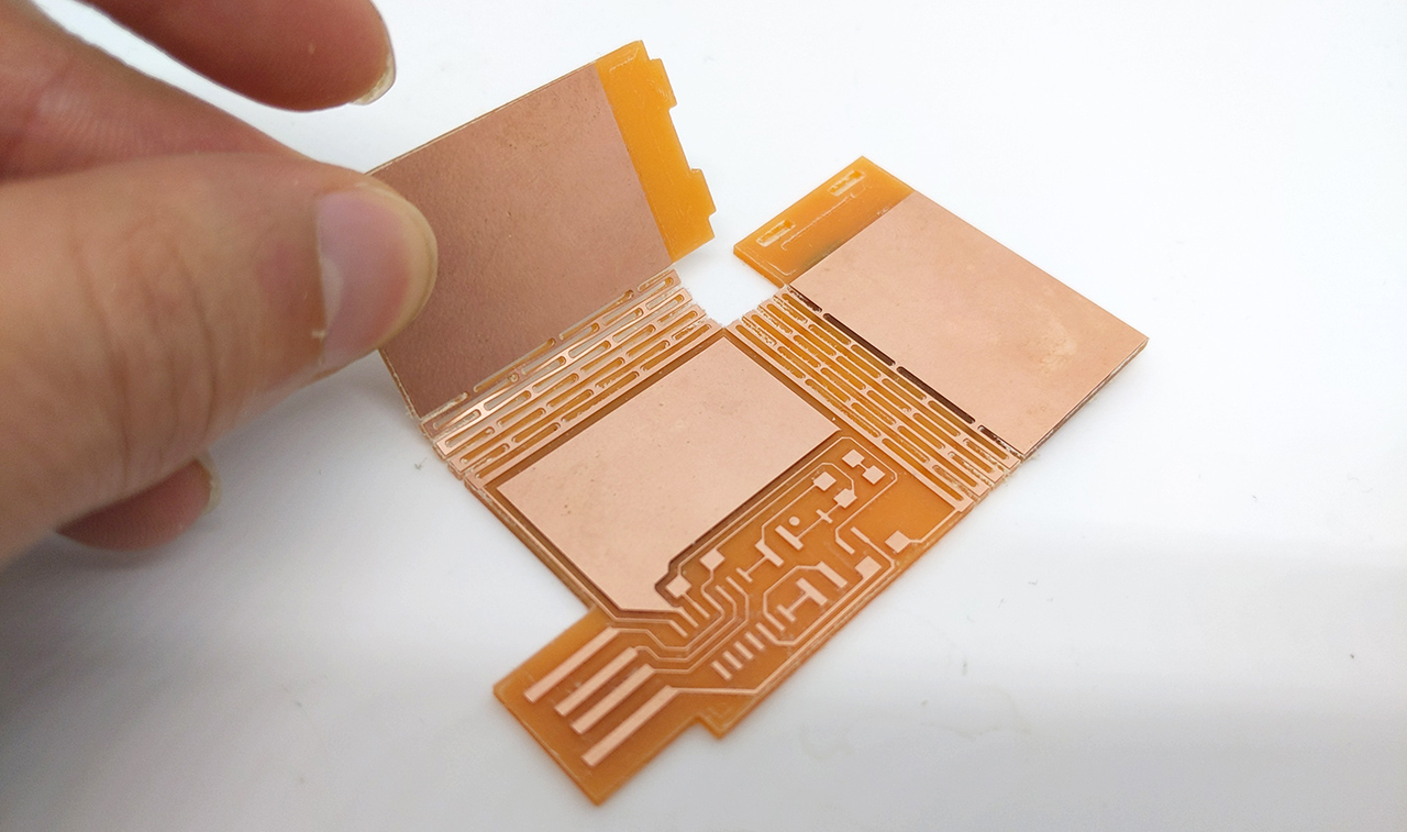
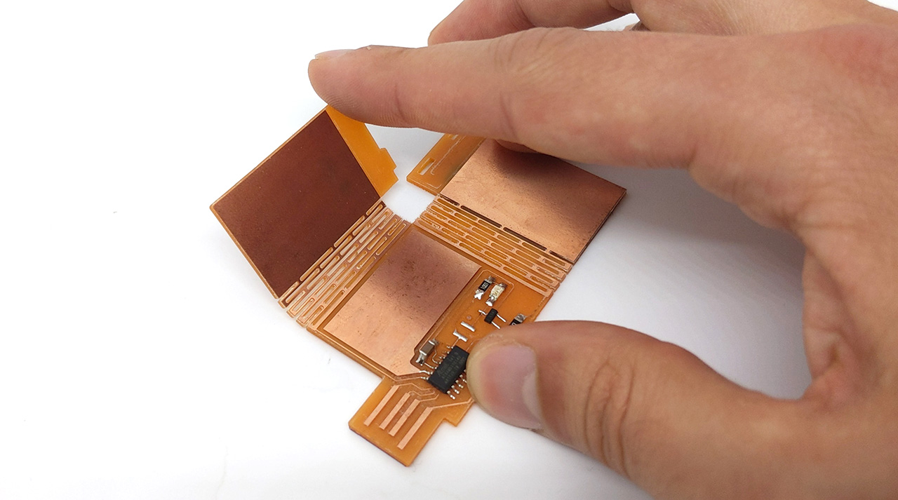
Here, flexures are used to connect capacitive sensing pads to the MCU. Bending those pads allows for capacitive sensing in 3 different directions and ultimately detecting a finger’s 3D position:
Design
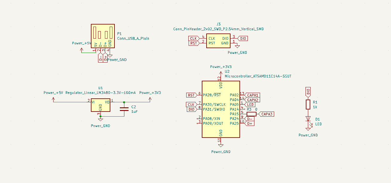
Schematic
This board is designed to have as few elements as possible. The LED and resistor could also be removed, but I like to have an indication of the board being connected.
There is a single 0-Ohm jumper I wasn’t able to avoid. The 3 capacitance pads are just wires here, but they will each receive a copper fill in the board’s design.
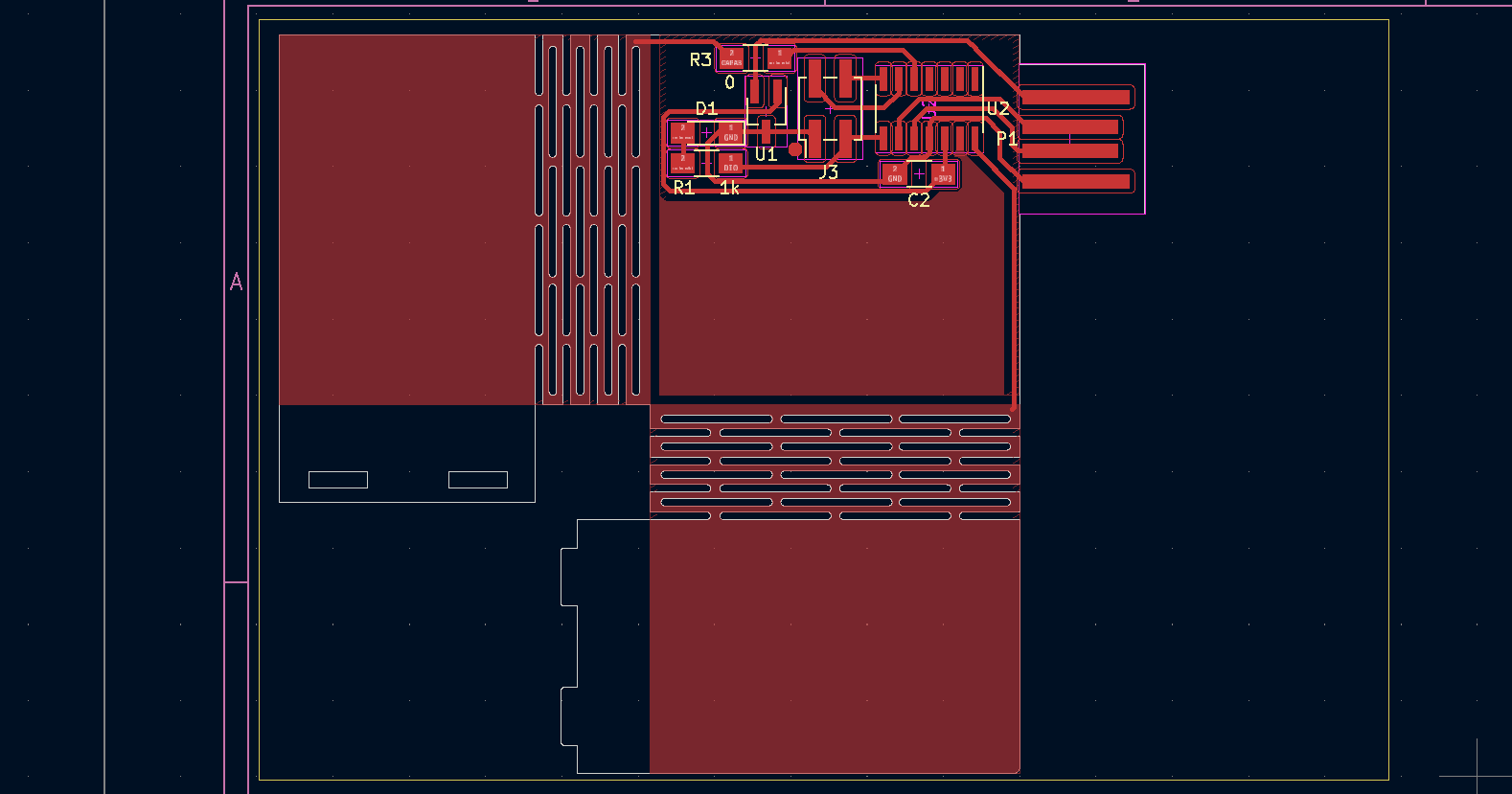
Board
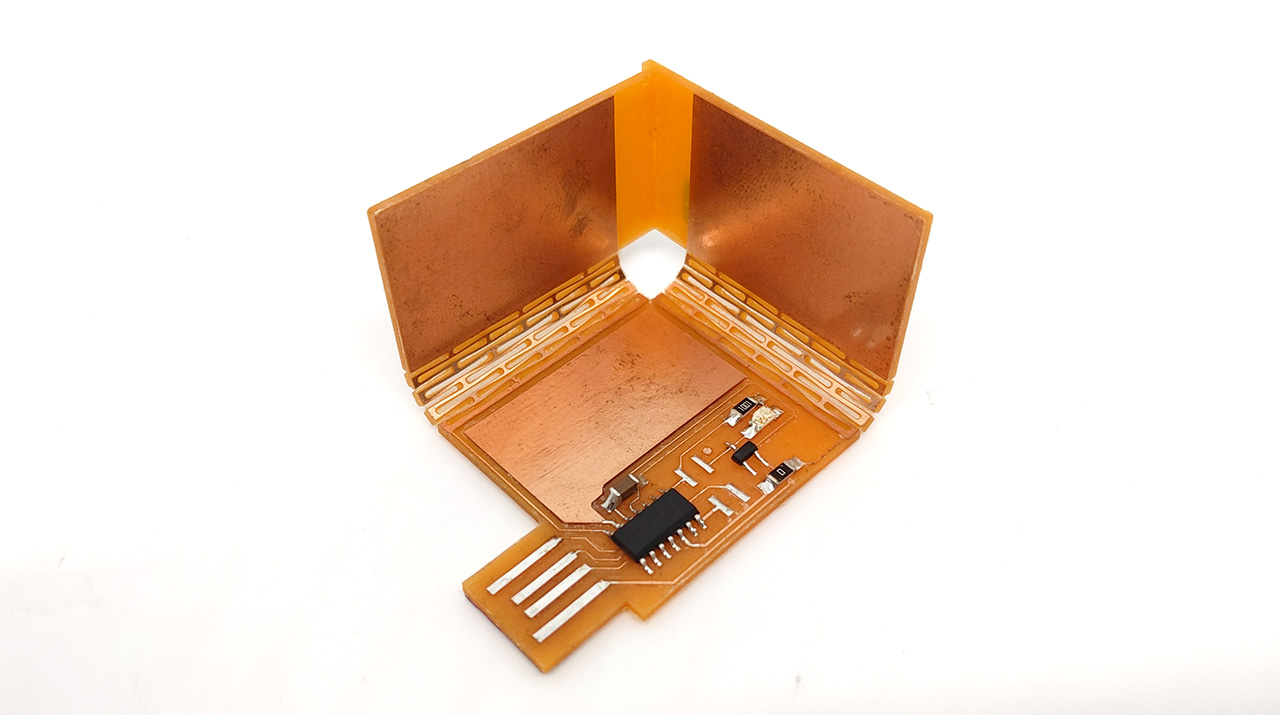
Designing an usual board in KiCad was somewhat fun. After placing the components, I realized I would need to make compromises or the whole board wouldn’t fit on the 94 x 64 mm FR1 boards we use at the lab. This sadly means the two flaps are rectangular rather than squares, limiting the XYZ volume after bending.
I included two tabs so the PCB would remain closed on its own. Their exact sizes and positions were half-guessed but lined up reasonably well in the end.
One other design limitation is the bottom pad, it’s limited in area due to the components. This will result in a dead zone in which the finger’s height can’t be sensed.
Production
The whole board was processed in mods, you can find the PNG files at the end of this page.
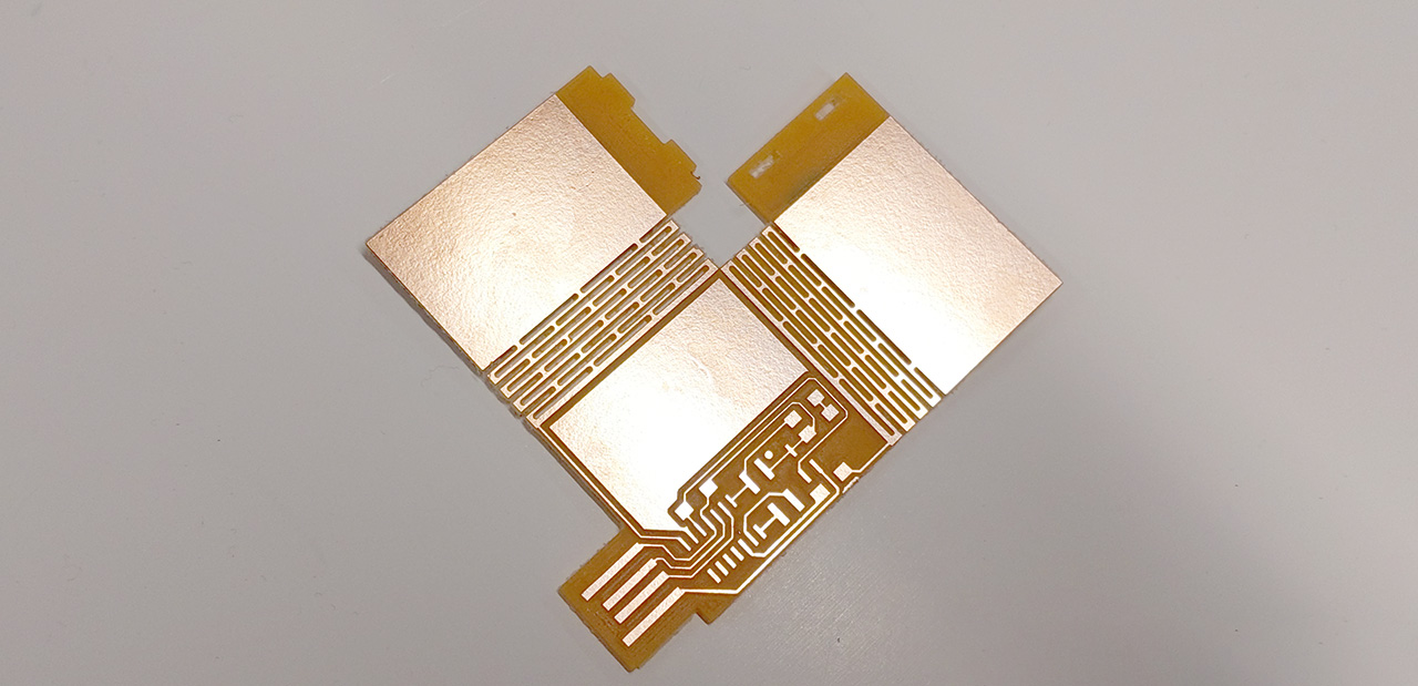
The traces were first isolated with a 0.4mm flat end mill. For clearing the remaining copper as well as cutting the flexures and board cutout, I went for a 0.6mm flat end mill.
On a Wegstr CNC, this job took around 40 minutes in total.

The board came out perfect on first try, but requires a lot of cleanup in the flexural areas.
The flexing is very satisfying to experience first-hand, I highly recommend it.
After stuffing the board and flashing the D11 with the sam BA bootloader, I assembled the board in its final configuration.
Note the lack of programming connector on the D11, I simply pressed a 2x2 connector during flashing. I still decided to tin the pads for reasons explained later.
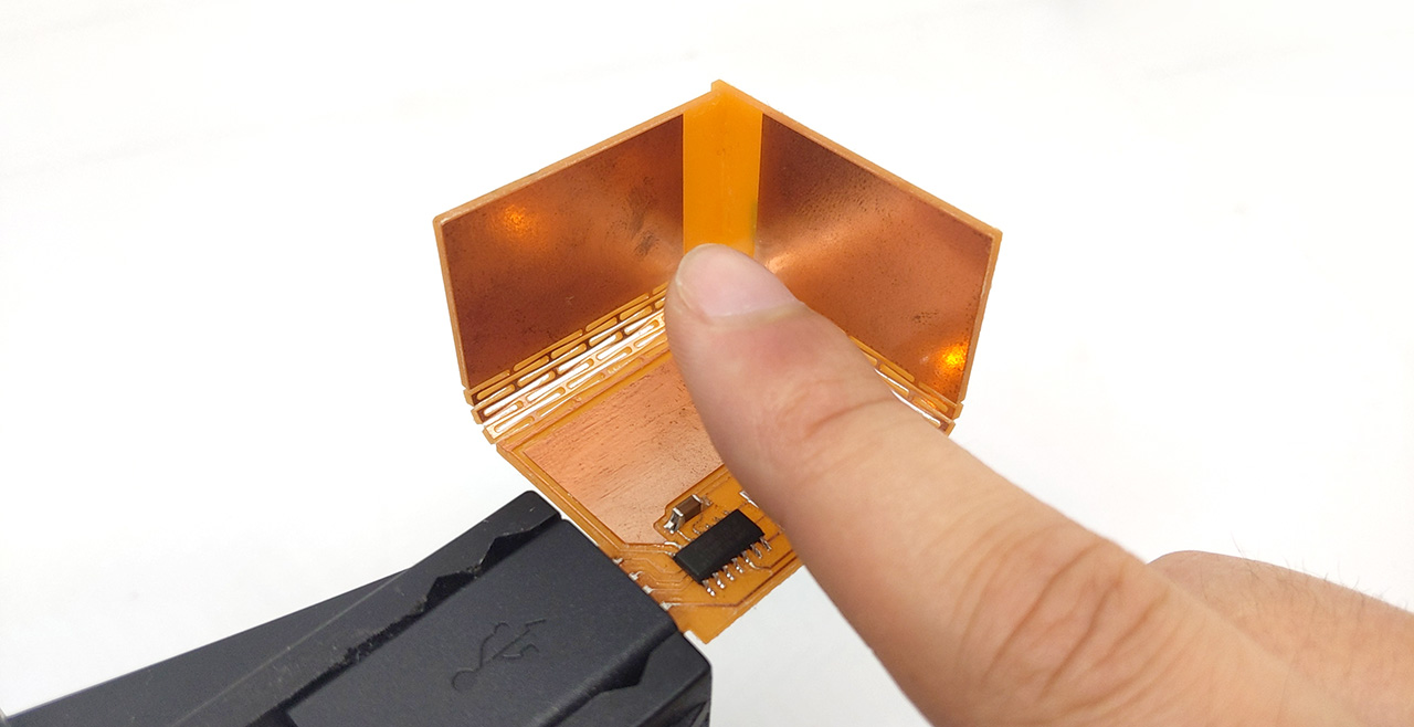
The board holds it shape on its own, but I decided to permanently bind the tabs with epoxy, then apply nail polish to prevent copper corrosion. During that step, I like to tin the connectors (with a minimal amount of tin to prevent bumps) and not apply nail polish on them.
The board is ready to spit out 3 capacitance values with no additional hardware thanks to the Qtouch system embedded in the SAMD11.
Demo
Here is a demo with a simple visualizer made with vpython:
Code
The code is straightforward but makes use of my Adafruit FreeTouch branch, as the SAMD11 is normally not supported.
Each pin is assigned to a qtouch object, providing a 10-bit capacitance value. I decided to oversample the measurements for sub-unit accuracy, but there was not enough flash left on the D11 for floating point arithmetic, so I’m dumping the sum of the measurements on the serial port, letting the host do the division by the oversampling factor (here 32).
#include "Adafruit_FreeTouch.h"

#define PIN_QT1 2
#define PIN_QT2 4
#define PIN_QT3 15

#define PIN_LED 31

#define N_SAMP 32
#define N_QT 3

char qt_pin[N_QT] = {PIN_QT1, PIN_QT2, PIN_QT3};

Adafruit_FreeTouch* qt[N_QT];

bool error = false;

void setup() {
  int qt_value;

  pinMode(PIN_LED, OUTPUT);
  digitalWrite(PIN_LED, HIGH);

  SerialUSB.begin(0);

  for (int i = 0; i < N_QT; i++) {
    qt[i] = new Adafruit_FreeTouch(qt_pin[i], OVERSAMPLE_32, RESISTOR_20K, FREQ_MODE_NONE);

    if (!qt[i]->begin()) {
      error = true;
      return;
    }
  }
}

void loop() {
  if (error) {
    return;
  }

  for (int i = 0; i < N_QT; i++) {
    int32_t qt_diff = 0;

    for (int j = 0; j < N_SAMP; j++) {
      int qt_value = qt[i]->measure();
      qt_diff += qt_value;
    }

    SerialUSB.print(qt_diff);
    SerialUSB.print(" ");
  }
  SerialUSB.println("");

  delay(10);
}
I quickly hacked together a viewer based on vpython, you’ll find the code at the end of this page. One detail is how I convert capacitance values to distances: I decided to simply measure a lookup table by moving my finger at a constant rate. This is not an ideal method but provides enough accuracy for an interactive demo. The resulting curve is far from the inverse law an ideal (infinite) capacitor would display:

License
This project is provided under the MIT License.
Downloads
PNG files
Preview:

Interior:

Copper:

Mask:

Silkscren:
