6. 3D Scanning and printing
This week’s assignment is split in two parts:
- Try out some 3D scanning methods
- 3D print an object that could not be made using subtractive manufacturing
In our group assignment, we have tested and calibrated the 3D printers availabe in our lab, namely:
- one Form 2 from formlabs, based on SLA.
- 6 original Prusa MK3, which uses FDM.
However, I also used a 3D printer I have at my home. The main reason was to save time, as our lab is often very busy when it comes to 3D printing.
3D printer: quick look
3D printing is a very personal topic for me. Back in 2015, building my first 3D printing kit introduced me to the DIY philosophy, and naturally led me to discover FabLabs. I bought a reprap Prusa i3.
The reprap project is an ambitious idea, in which a 3D printer should be able to replicate itself. In its current state, only some critical component are 3D printed, you still need to outsource the electronics and most mechanical parts. However, those are pretty generic, and the modularity of the 3D printed parts allow this project to evolve over time.
Some frustration arising when building my own kit has led me to try and improve it. As I never documented this process, I here take the opportunity to present some of the features of my custom 3D printer, in case it might be useful to someone. If you are interested in my modifications, please contact me. I plan to share the designs and make then open source if enough people are interested.
The first feature is a lasercut enclosure, with acrylic windows and LED lighting.
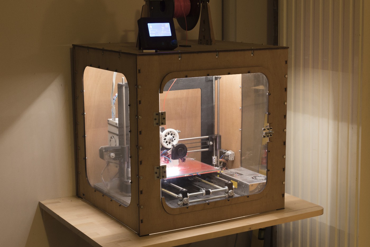
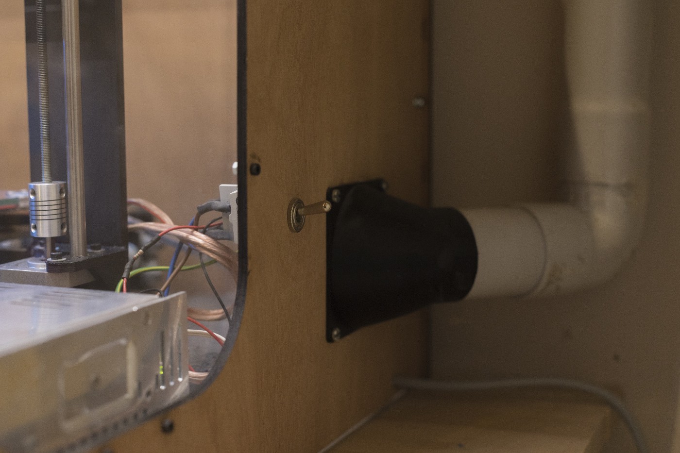
The enclosure helps in retaining some of the heat from the buildplate. This partially prevents warping when printing large parts. The main purpose of the enclosure, however, is to safely extract the ultrafine particles emitted when melting the plastic in the hotend. This is achieved through a simple exhaust fan and piping.
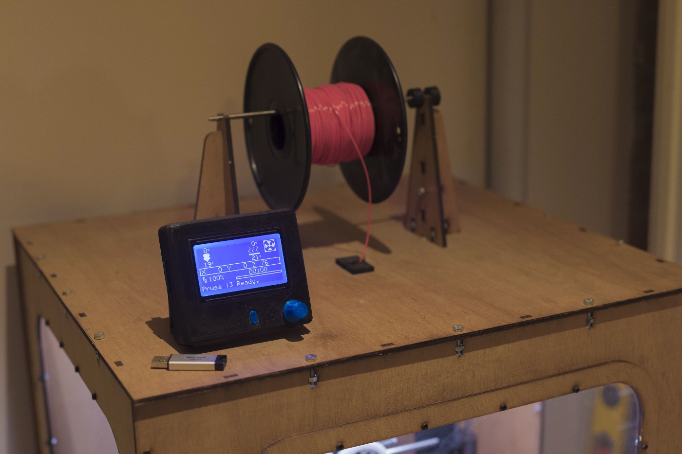
The control panel and the filament are accessible through the top of the enclosure, so that they can both be adjusted without needing to open the door. The printer runs on the Marlin firmware.
The printer itself is a modified Prusa i3. The steel frame is the only “authentic” part, the rest was outsourced from various websites.
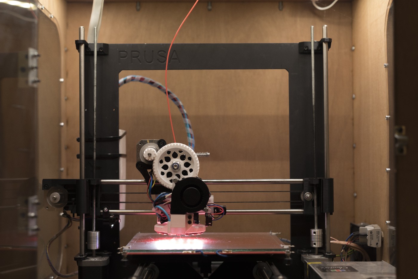
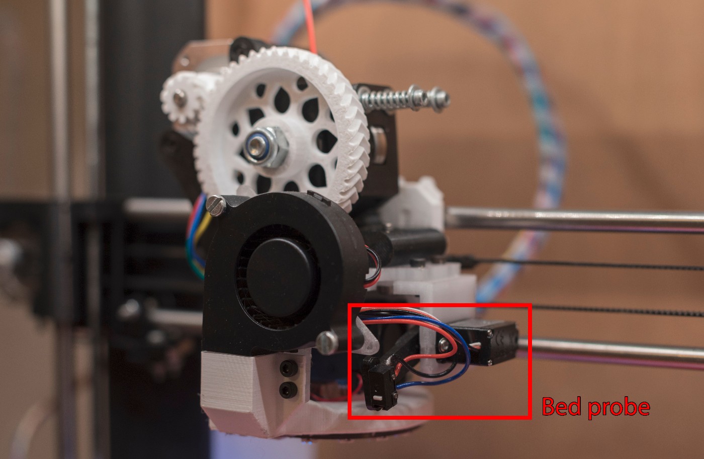
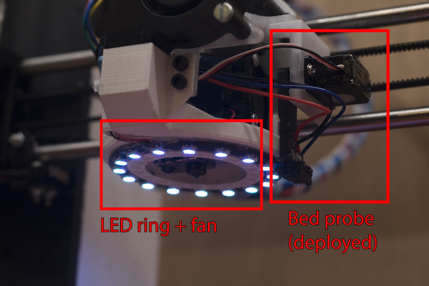
Next to the hotend, I installed a servo motor + micro switch. This is a nice method for probing and leveling the build plate. Unlike hall effect sensors, the micro switch does not require metallic probing points on the buid plate. In my case, the build plate is glass only.
All around the hotend is a circular fan design that allows cool air to reach the tip of the hotend from all angles. This is critical when printing angled surfaces, as the plastic should immediately cool down below its melting point when exiting the nozzle. I added an LED ring, for which the color can be customized in the firmware. Special gcode instructions even allow color changes during print, e.g. to indicate the status.
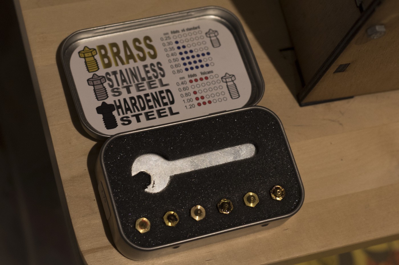
The hotend is V6 all-metal hotend from E3D. The nozzle can be swapped for various sizes, all the way to 1mm hole diameter for larger prints.
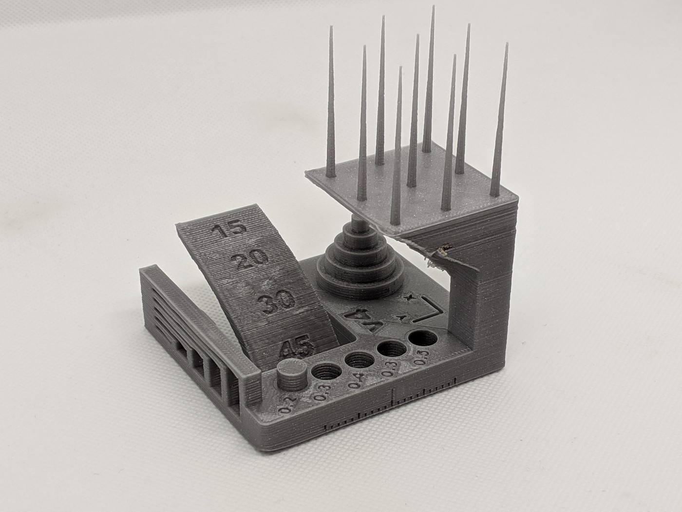
Finally, I tried to print the same calibration plate as in our group assignment. The result seems equivalent to what an official Prusa MK3 can achieve. As a bonus, I managed to adjust the retraction settings to completely cancel the stringing on the spikes, with the following settings:
- Rectraction length: 1mm
- Rectraction speed: 50mm/s
3D scanning: photogrammetry
3D scanning is an incredicbly effective method for digitalizing content from the physicial world. As one its applications, it can be used to create a digital copy of cutural heritage, for preservation purposes.
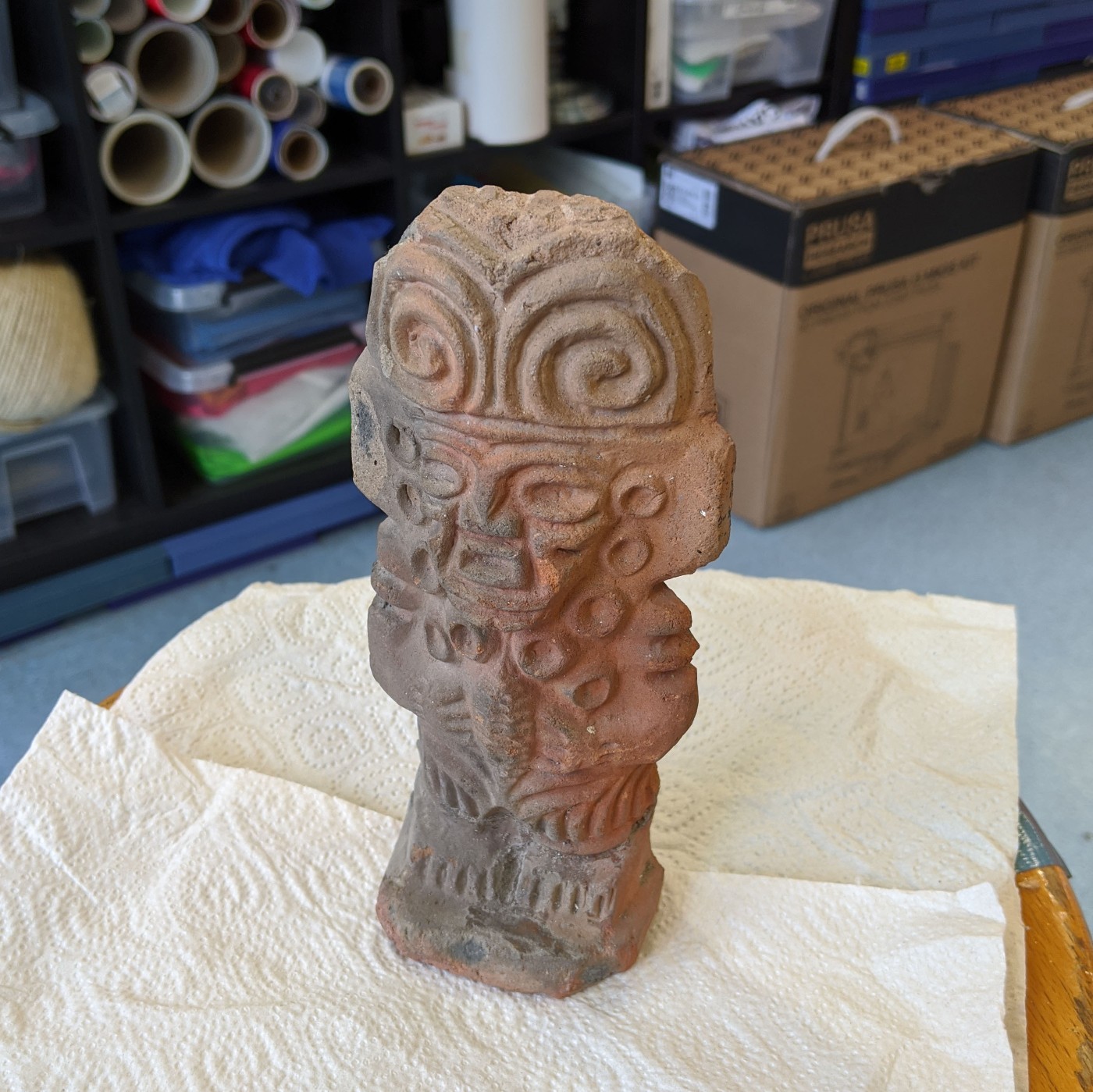
To try this, I decided to use photogrammetry on a pre-columbian statue that has been in my home for some time now. It is an ideal object to 3D scan, as there is no reflection, and plenty of textures for feature detection/matching.
I first make sure to place the object on a diffusive ground, with only static objects in the frame. I captured around 25 images with the camera of a Google Pixel 3, from various angles.
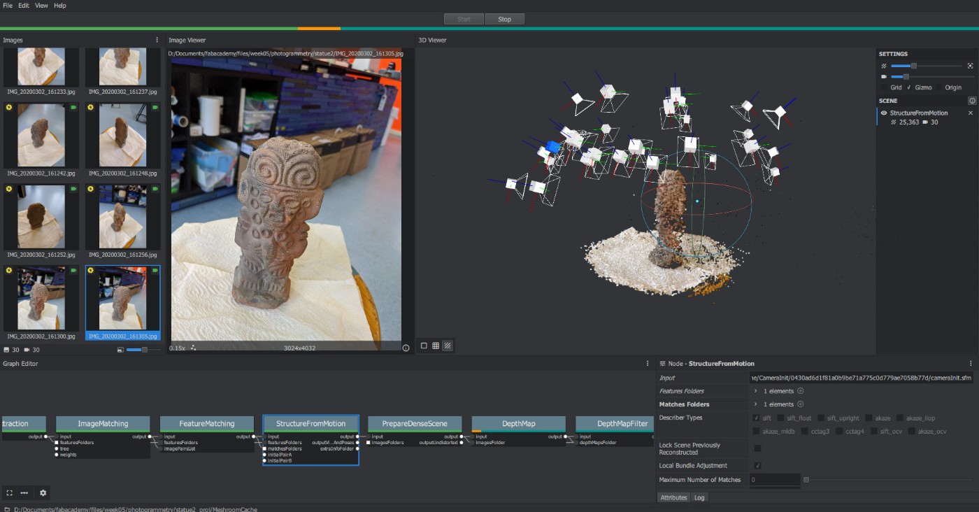
The images are imported in Meshroom. Thanks to its large database of sensors, it is already aware of the parameters for my camera. Those are:
- Sensor width: 5.76mm
- Focal length: 28mm equivalent
It should be noted that the focal length, as well as the camera distortion parameters, are estimated by Meshroom itself during the camera pose estimation. In the 3D preview, we can clearly see all the camera poses accurately reconstructed.
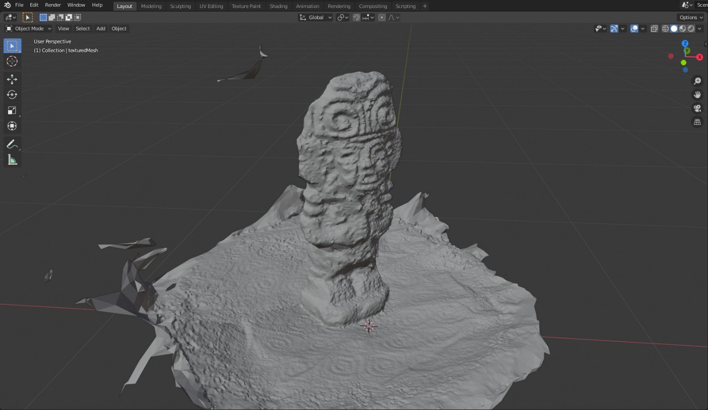
The resulting mesh is incredibely detailed, including the small dents on the paper I placed under the statue. The statue itself, however, has some noise on the details. I estimate the precision of the result to be around 2mm of accuracy, which is still fairly impressive.
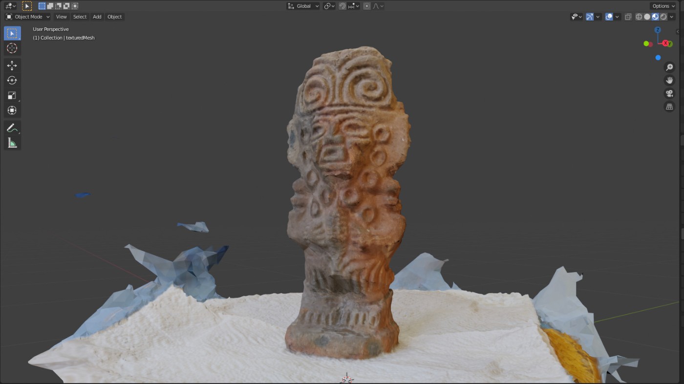
Meshroom also produces a texture files, which can be mapped to the reconstructed surface. Although this cannot fix the errors in the geometry, it helps in bringing back some of the visual details.
3D scanning: structured light
I tried another method for 3D scanning using a Sense 3D device. This is a very different technology, which projects a light pattern onto the scene to help detecting features. The pattern is a series of infrared dots and is not visible to the end user.
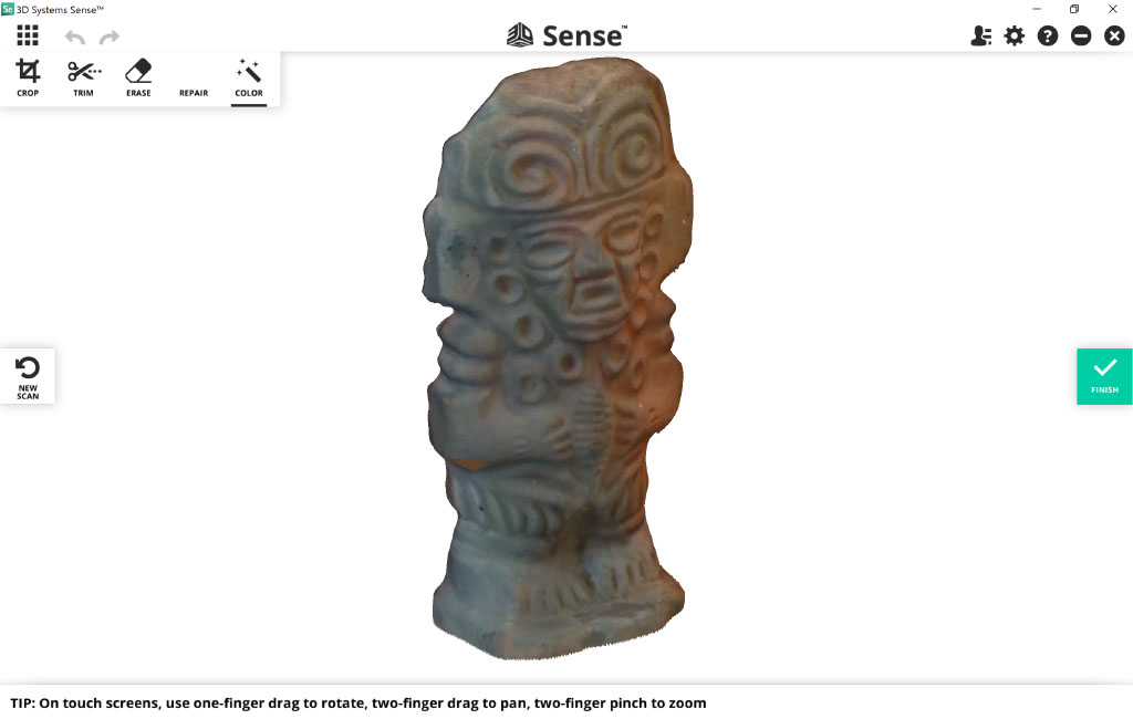
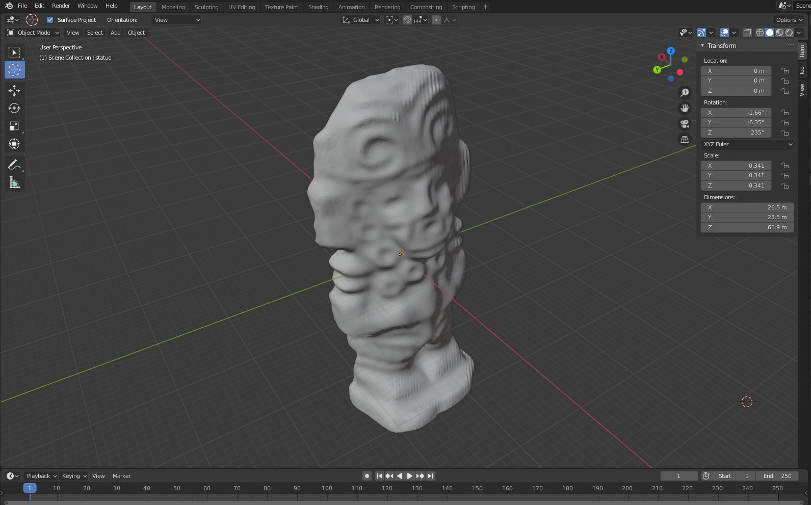
After sweeping the device all around the object, a full 3D model is obtained. The result is remarkably smooth compared to photogrammetry, however small details are lost. As with photogrammetry, a texture file is available.
3D printed object
For my 3D printing assignment, I decided to create a paradoxal screw, on which a nut is already in place. This could not be achieved through subtracting manufacturing, because no tool could easily reach the inside of the nut to form the thread.
I start with a simple design in Fusion 360, which makes use of the powerful Create -> Thread tool.

However, I found that ISO thread settings would not work for me, as I need a very large thread. Additionally, I want the angle of the threading be 45 degrees to make sure it’s printable. Luckily, I found a method to create custom thread settings. I first creat a file located at:
%localappdata%\Autodesk\webdeploy\Production\<version ID>\Fusion\Server\Fusion\Configuration\ThreadData\ISO_custom.xml
In the file, I add the following information to get a 25mm thread with a pitch of 16mm:
<?xml version="1.0" encoding="UTF-8"?>
<ThreadType>
  <Name>ISO Custom</Name>
  <CustomName>ISO Custom</CustomName>
  <Unit>mm</Unit>
  <Angle>90</Angle>
  <SortOrder>4</SortOrder>
  <ThreadSize>
    <Size>25.0</Size>
    <Designation>
      <ThreadDesignation>TR25</ThreadDesignation>
      <CTD>TR25</CTD>
      <Pitch>16</Pitch>
      <Thread>
        <Gender>external</Gender>
        <Class>25e</Class>
        <MajorDia>23.6</MajorDia>
        <PitchDia>20.2</PitchDia>
        <MinorDia>16.6</MinorDia>
      </Thread>
      <Thread>
        <Gender>internal</Gender>
        <Class>25H</Class>
        <MajorDia>25</MajorDia>
        <PitchDia>21.5</PitchDia>
        <MinorDia>18</MinorDia>
        <TapDrill></TapDrill>
      </Thread>
    </Designation>
  </ThreadSize>
</ThreadType>
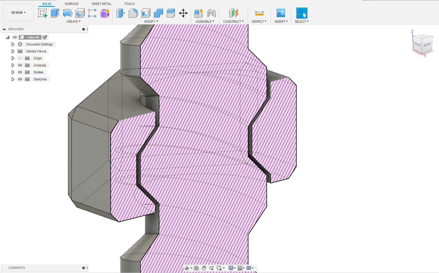
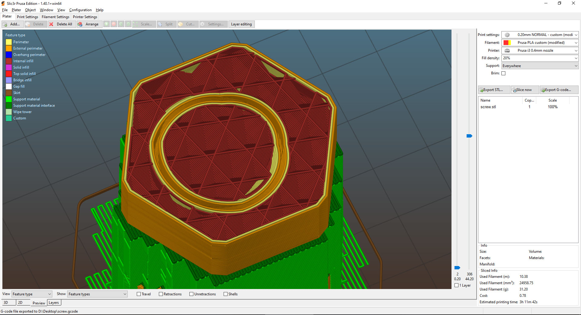
A sliced view of the part allows me to check the tolerance. I first set a tolerance of 0.4mm, hoping the nut would not fuse with the screw.
I Add both objects in Slic3r, and slice it with the following settings:
- Layer height: 0.2mm
- Support: under 20 degrees
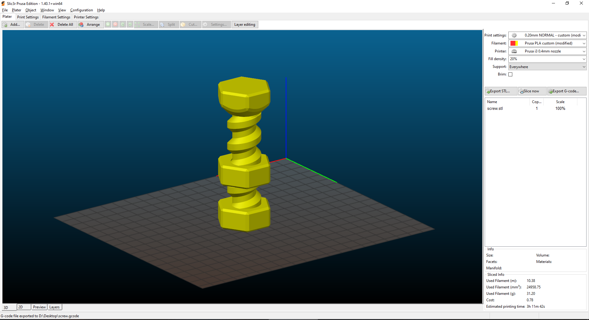
The support is only needed for the underside of the nut and should be easy to remove.

I quickly check some layers to visualize the solerance between both parts.
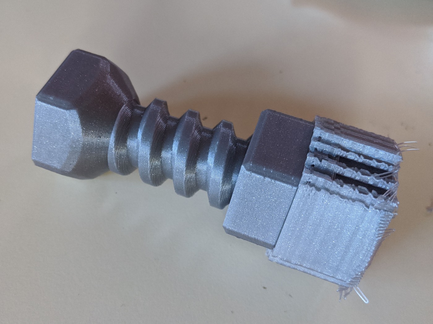
I print the part on our original Prusa i3 MK3 with some PLA filament.

The part looks smooth and accurate. Unfortunately, when removing the supports, I realized the nut and the screw had fused and I could not used the part. The main reason it that the tolerance I used was too tight for such an angled piece.
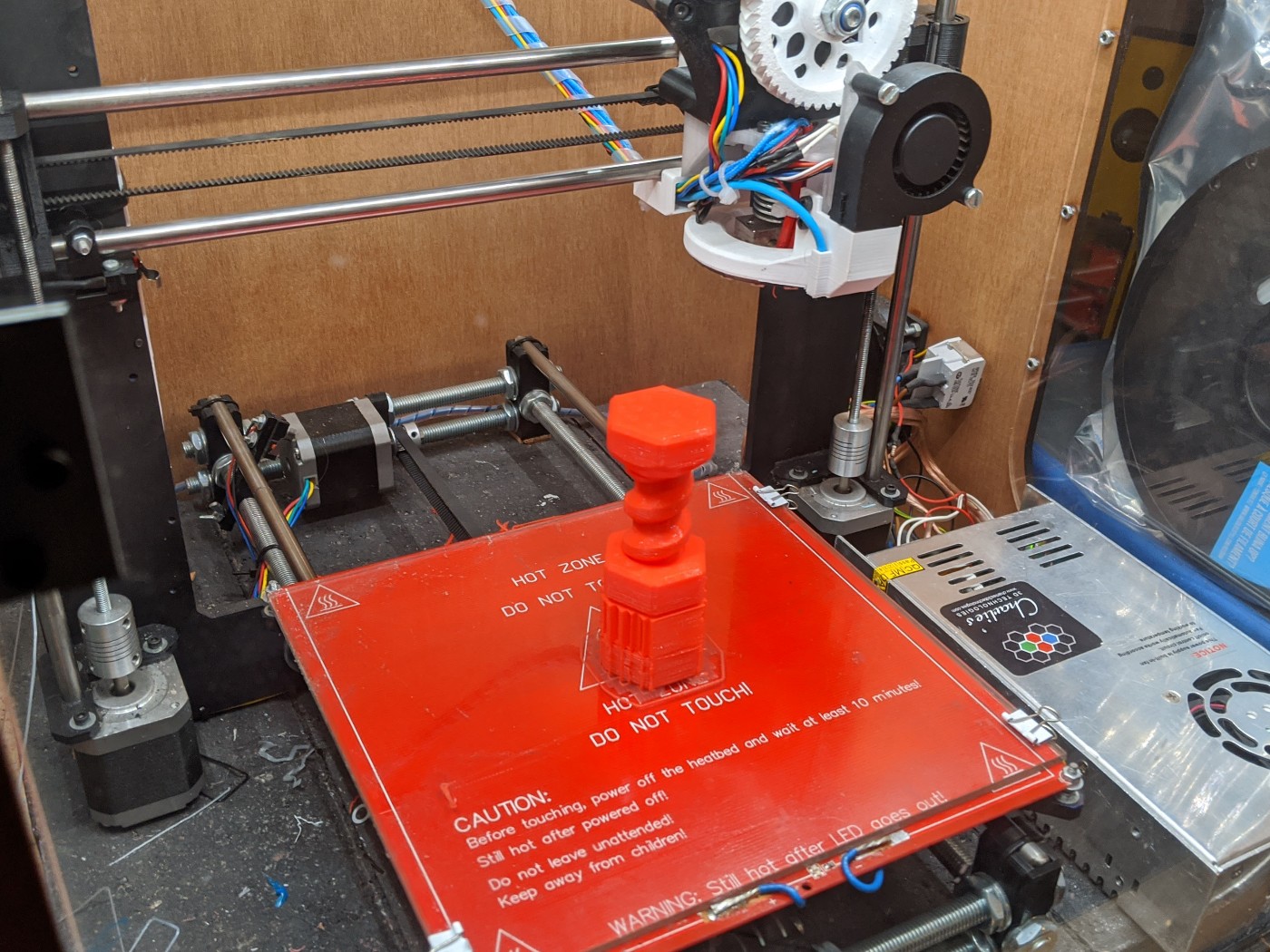
After setting the tolerance to 1mm, I print the part again on my home 3D printer. I also use PLA, with 0.25 layer height to save some time. The print took 3 hours.
Removing the support material was easy using a set of pliers.
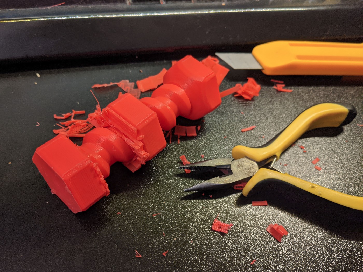
I immediately checked whether the nut was free to spin, and I was relieved to see it was the case.
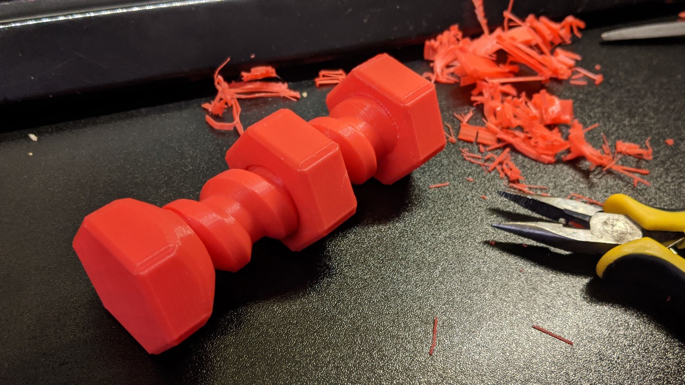
The 45 degree slope was not an issue during printing, we can see that all the features are present.

Suprisingly, this object is actually a pretty fun toy. The large tolerance on the nut means that gravity alone is enough to pull it.