11. Applications and implications
This week’s assignment is dedicated to planning the final project. This includes defining which functionnalities will be included, as well as all a bill of material and the fabrication methods for each part.
Final project: photogrammetric 3D scanner
My final project is a photogrammetric scanner with 2 degrees of freedom. The object to be scanned is placed on a moving platform, and a series of pictures are taken with an embedded camera.
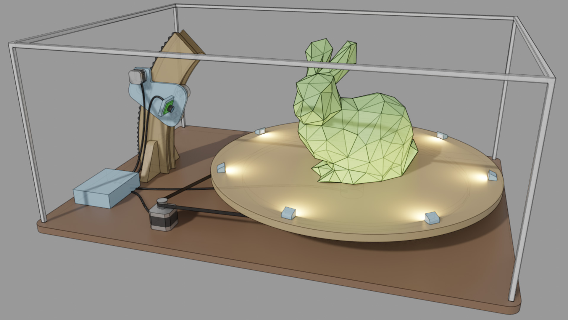
Let’s quickly highlight the role of each component:

There are two stepper motors connected to the electronics box. The camera can move in a vertical direction thanks to a gear rack. The central platform is carried with a timing belt, and rests on a set of bearings to keep a clean motion regardless of the object’s weight. A set of LED embedded directly on the platform ensure a consistent lighting of the object. The LED are mainly lighting the object from the bottom, and this could be an issue when viewing the top of the scan. If this is an issue, a more complex lighting setup can be added, but this might not be needed thanks to light already present in the room.
What will it do?
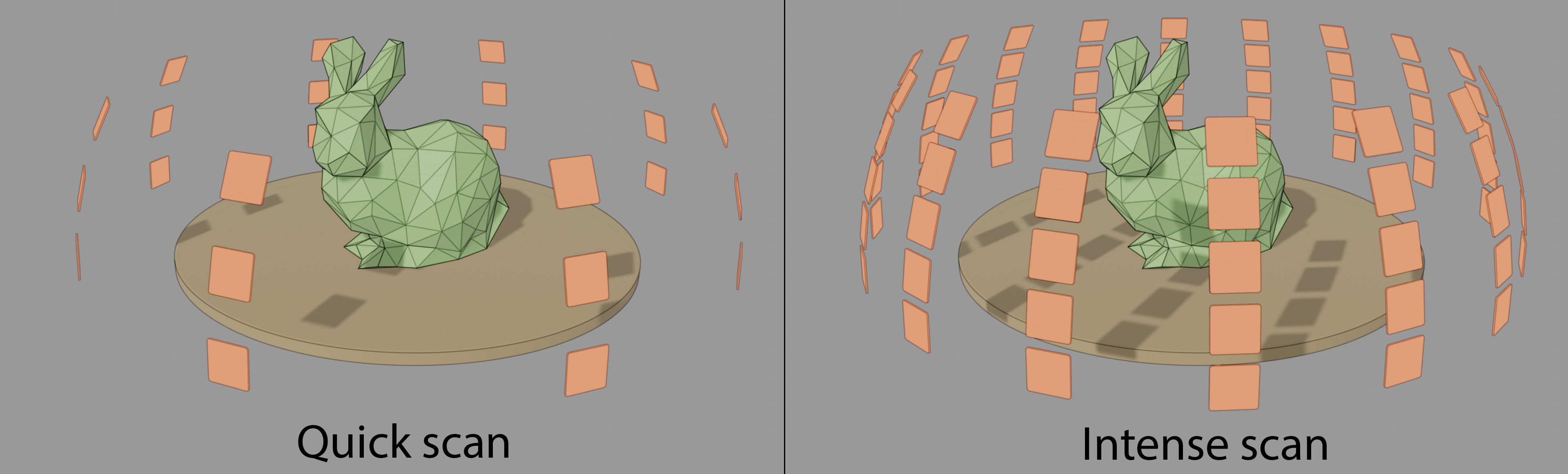
The main purpose of this device is to shoot color images of the object across a wide range of angles/positions. Thanks to the two degrees of freedom, the density of “virtual cameras” around the object is parametric:
The collection of images is then sent to a PC equipped with the open source photogrammetry software Meshroom. This software is able to reconstruct the 3D shape of the object and detect the position of each camera automatically. New images can be added on the fly, and the accuracy of the 3D geometry is almost always improved with the number of shots. This hints that the scanner could be used in a dynamic way, uploading pictures as they come, and possibly refining some areas if needed.
Communication with the PC is ensured through a serial communication with a SAMD11C14 microcontroller. Ideally, the data for each picture should also be sent through this USB connection, but depending on the type of camera I end up using, there might be an additional USB cable just for that. An alternative is to use a network-enabled camera such as the ESP32 camera module.
Who has done what beforehand?
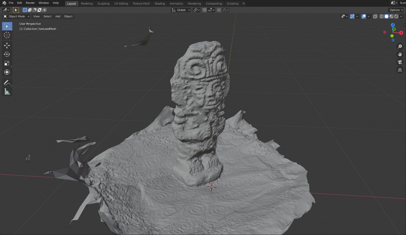
During the week on 3D Scanning and printing, I quickly tested the Meshroom software, and found good results with a simple smartphone camera.
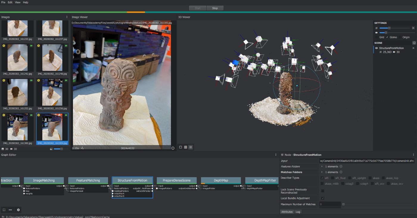
The geometry was about millimeter-accurate with 30 input pictures.
When it comes to the electronics, I can re-purpose the ATtiny1614 board I designed during the electronics design week:
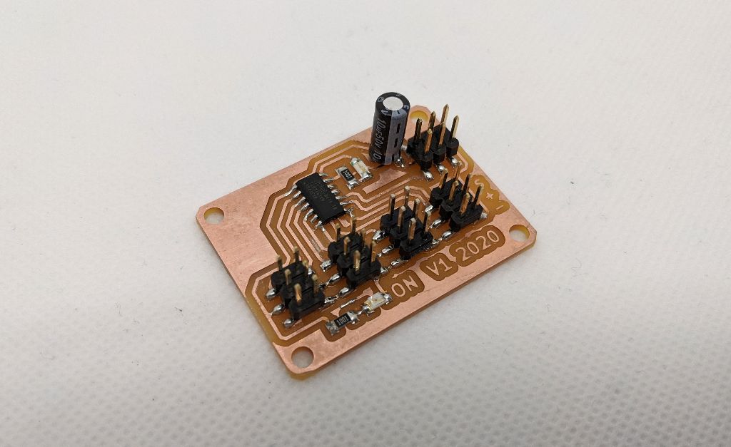
I plan to use the ATtiny for low-level tasks such as driving the stepper motors and the LEDs. Its serial port can be used to communicate with the main board with simple 1-byte messages.
I also searched for similar projects in the fabacademy history. The only similar idea I found is the FABMAT 3D SCANNER in 2016, but there are several key differences:
- They use an Intel 3D RealSense as the sensor, which is already a 3D scanner in itself based on structured light.
- The camera moves in a vertical motion, while we are aiming for a spherical motion thanks to our arc motion system.
- Lighting is not handled, as their sensor can emit its own light.
What will you design?
All mechanical parts need to be designed in a CAD software. The main components are:
- The wooden arc that holds the camera.
- The rack gear attached the back of the arc, with adequate gear teeth.
- The corresponding gear shaft for the stepper motor.
- The part holding the camera.
- A rotating platform with placements for high power LEDs.
- A box for the electronics.
- A main board based on a SAMD11C14, with a mini-USB port and 12V input.
What materials and components will be used?
- 1-2 sheet of 18mm MDF, 610x1220mm each.
- 2 12V stepper motors + driver.
- A 12V power supply
- A timing belt for the platform
- The slip ring that brings current to the LEDs
- A few high power LED to brighten the object.
- A few meters of 1mm² electric wire.
- All required SMD components for the main board (microcontrollers, resistors/caps/voltage regulators).
- An embedded webcam, most likely the ESP32 camera module
- About 1000x800mm of acrylic for the various gears.
- Some metal beams and black fabric to cover the entire project if lighting is not adequate.
Where will they come from?
The main board electronics is provided by my local FabLab. The stepper motors, timing belt, drivers, slip ring and 12V power supply are available from previous personal projects. I need to order online:
- Power LEDs for the platform
- The camera module
From my local store, I will buy the required wood and acrylic supplies.
How much will they cost?
The stepper motors/belt/drivers/power supply would cost less than 30€ if bought online. The camera module could be as cheap as 16€.
I estimate the construction material cost (screws, bearings, wood, acrylic, 3D printing plastic) to be around 35€. In total, it seems possible to build this project for significantly less than 100€.
What parts and systems will be made?
The electronics box will only contain homemade boards and circuits that will drive the stepper motors and the LEDs. Communicating with the PC is ensured with a custom board embedding a SAMD11C14 chip.

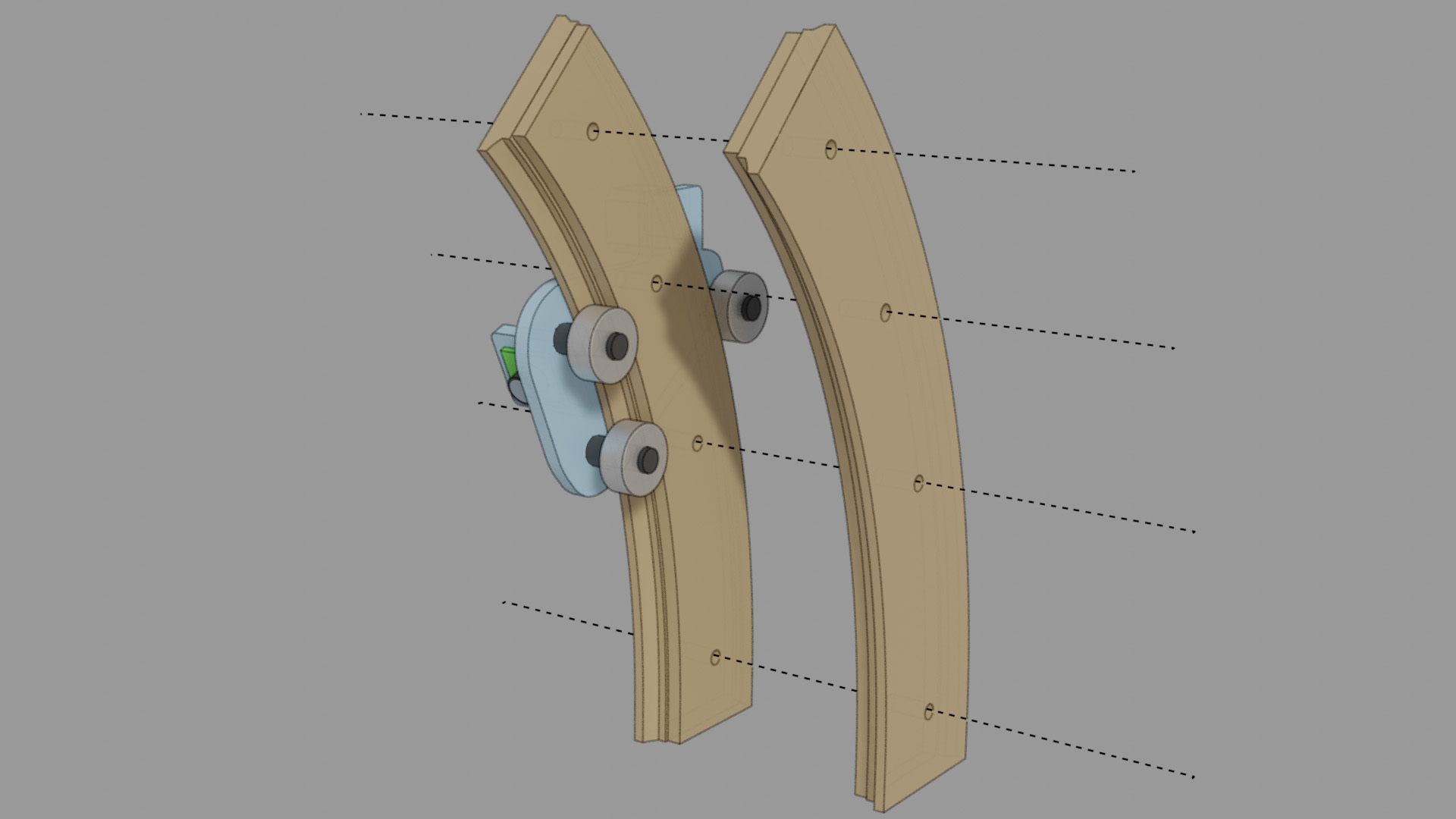
The other important system is the moving rail for the camera. It is an entirely custom wooden part produced with a CNC. The groove can be performed by the CNC by splitting the part in two, and assembling it later on with screws.
Other custom mechanical parts include the main gear for the timing belt, the bearing holders for the two moving parts, and the rotating platform with housing for the LEDs + wires.
What processes will be used?
- 3D printing: electronics box, camera holder
- CNC machining: rotating platform, camera rail, bottom plate
- Laser cutting: rack gear and corresponding gear shaft
- PCB milling: main board
What questions need to be answered?
- How many pictures are needed for a sufficient 3D quality?
- Is the position of each virtual camera sufficiently accurate to entirely skip the camera bundle adjustment in Meshroom? If not, can this initial guess speed up the process?
- How can we transfer the images as efficiently as possible to the PC?
- Is it possible to completely cancel external light sources? Idea: by turning OFF/ON the LEDs and comparing the picture without/with LED lighting, it should be possible to remove external lighting almost entirely.
- How to mask the background pixels so that Meshroom is not confused about its lack of change? Idea: first take a picture without object, then write some image processing Python code with OpenCV to detect the “novel” pixels.
How will it be evaluated?
The project is successful if the 3D scanned geometry is accurate enough for some practical use. Namely, I would like to obtain near-millimeter accurate depth maps for my research. Another criterion for success is that the device should not require any user interaction once the object is placed on the platform and the “scan” button is pressed on the host PC.