SAMD11C14 devkit board

This project is an attempt at turning the SAMD11C14 into a ready-to-use general purpose board, similar to an Arduino.
In summary, it was made with the following philosophy:
- All pins used: offer all functionality of the chip.
- Readable text: every GPIO or power pin has an easy-to-read label next to it.
- JTAG ARM connector: provide a 10-pin standard JTAG connector for flashing and realtime debugging.
- Robust 3.3V regulator: a larger SOT223 regulator offers up to 1A of current for external devices.
- Serial port protection: the entire board is based on 3.3V, but a resistor protects the RX pin if used against TTL levels.
There are two versions of this board: one including a mini USB, and one without. In that case, an USB-A port is made directly from the copper plate. The mini USB port is strongly advised if you want a more durable, reliable connection to the PC.

Design
mini-USB variant
The board was designed in KiCad 5.1, starting with a basic schematic. All custom symbols used are included in the download files at the end of this page.
The schematic is exactly what you might expect: the SAMD11C is powered from a 3.3V regulator, itself fed from the USB 5V. the USB data lines directly go to the dedicated pins. A 2x5 JTAG connector is there for programming and debugging the board. All other pins are routed to 5x1 pin connectors. The hardware serial port is on pins 4 and 5, note that an optional 1.2k resistor offers injection current limitation on pin 5 (RX) in case a 5V serial line is connected there.
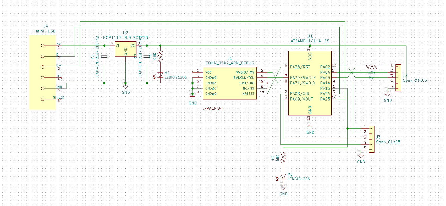
The capacitor values should be around 1-10µF, and LEDs are more visible with 680/Omega resistors or less. One LED is always ON to indicate the power status, while the other is optional and controlled by pin 15. Note that we do not get power from the JTAG connector; this means the board must be powered through USB also when programming.
I drew the board in a simple rectangular shape with optional chamfered corners. There is a ground plane all around the board, and I also left optional copper island in middle areas to speed up manufacturing.

The micro USB port is exactly in the middle of the top edge; note how its shield is not connected to anything else, as required by USB.
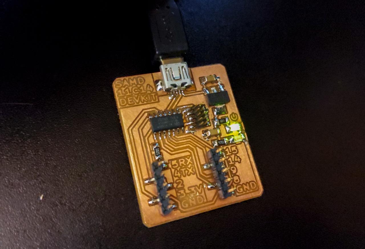
The GPIO pins are split in two 1x5 rows of pins, with the standard zig-zag layout for mechanical resistance. One important feature of the board is the embedded text, placed next to each available pin. The text is designed so it can be milled with a 1/64” tool, as the rest of the board.
USB-A variant
If you want to skip soldering of the mini-USB port, you can use this modified version that forms a USB-A connector from the copper plate. The schematic is enterely identical, except from one jumper 0~\Omega resistor on the D+ line.
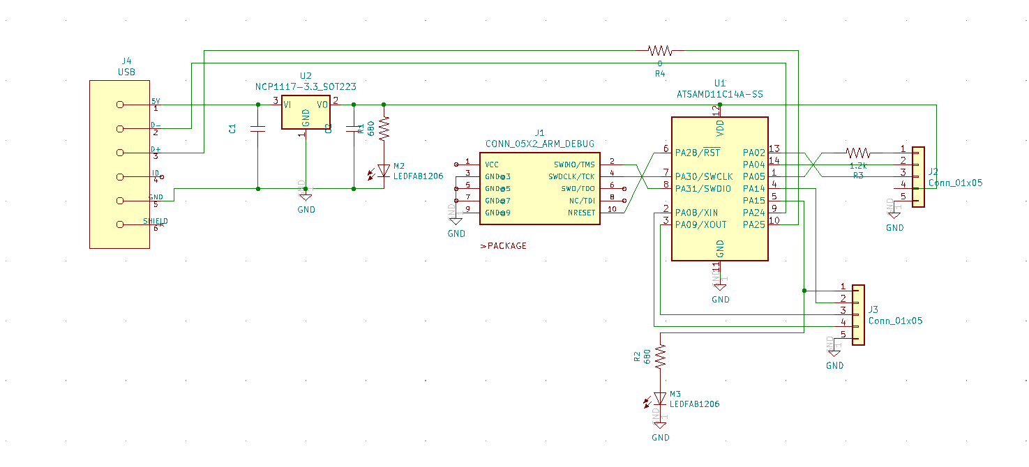
The USB-A port is implemented on the top edge of the board. Notice the voltage regulator is used as a bridge, and there is now a jumper resistor on D+:
The Gerber files are provided at the bottom of the page.
.png render
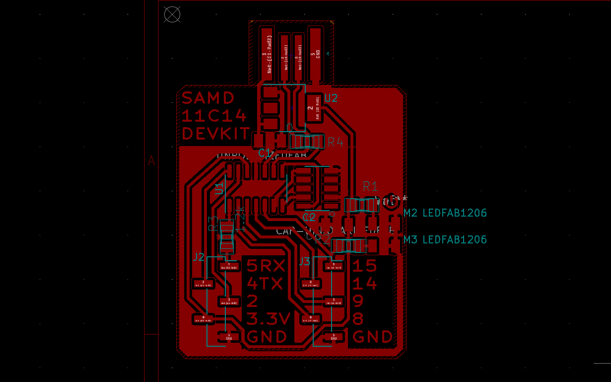
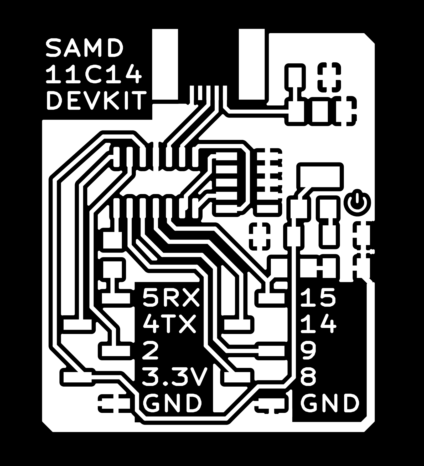
The provided Gerber files are the preferred method for manufacturing, but the boards are also available in .PNG format, rendered at 1000 DPI (click to enlarge):
| Interior | Traces | |
|---|---|---|
| mini USB |  |
 |
| USB-A |  |
 |
Production
Milling
Gerber files are provided at the end of the page, and can be produced from the KiCad files.
The entire board can be milled with a 1/64” tool in less than 30 minutes. For the edge, a 1mm tool is advised. I used a Bantam tool desktop CNC with their software to compute toolpaths.
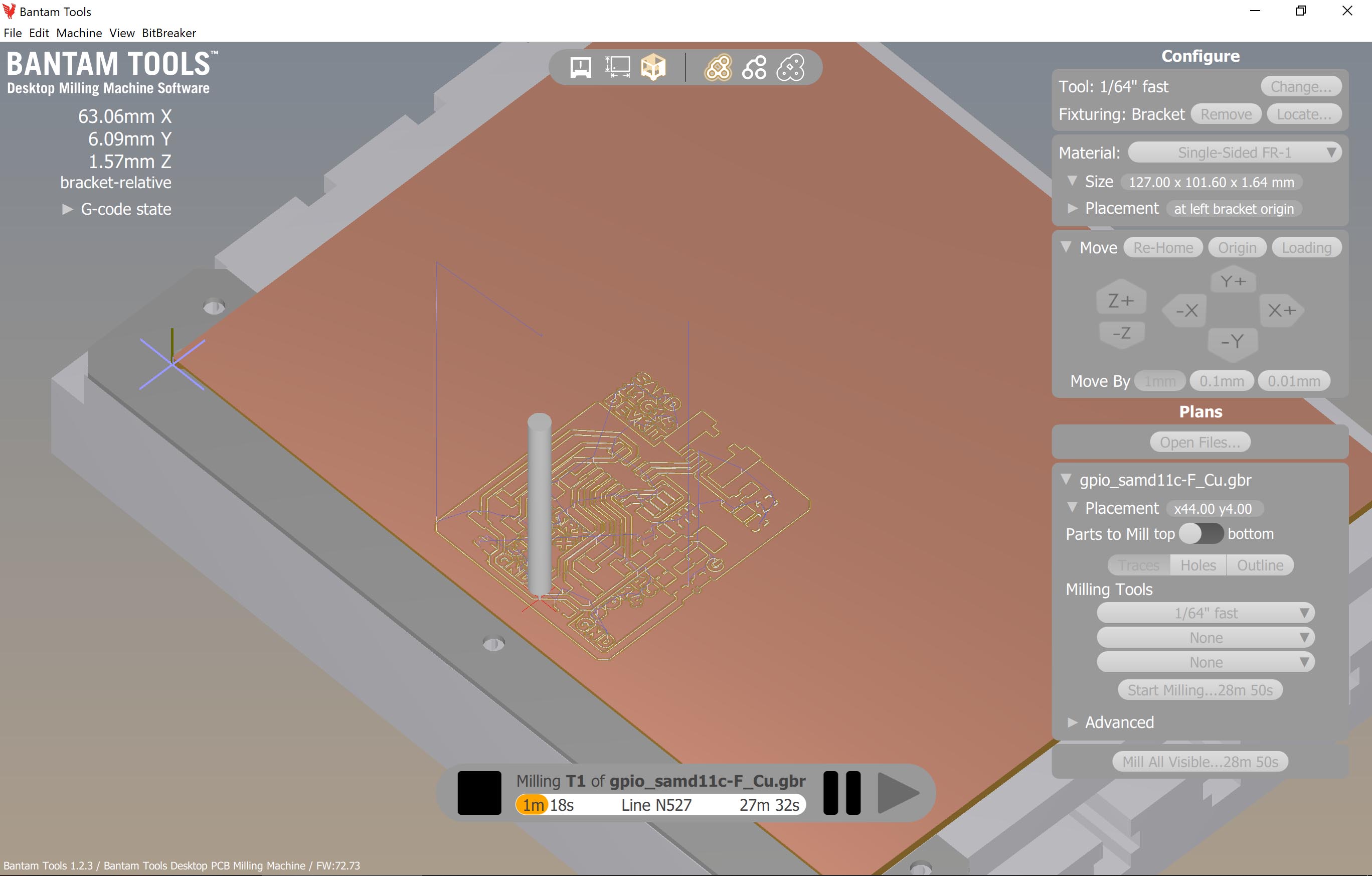
I start with an isolation operation with the 1/64” flat end mill. It came out flawless, with no need for retouching.

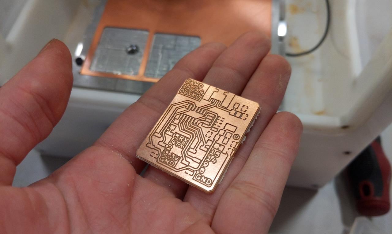
After the edge cut with a 1mm flat end mill, the board is ready for soldering. Very thin copper strands might still be floating around, in which case it’s safer to cut them out with a precision knife.
Soldering
Soldering this board might seem intimidating, as the track density is pretty high. However, if you follow the operation order, this can get significantly easier. I suggest to start with the mini USB port, as it has the finest pads. I put a tiny amount of solder on the side to secure the shield first.

After soldering both sides of the shields, I reach the USB pins with my finest solder tip available. It’s not strictly necessary to get a contact with the USB pins, it seems pretty good at sucking up the solder once the track reaches the correct temperature.

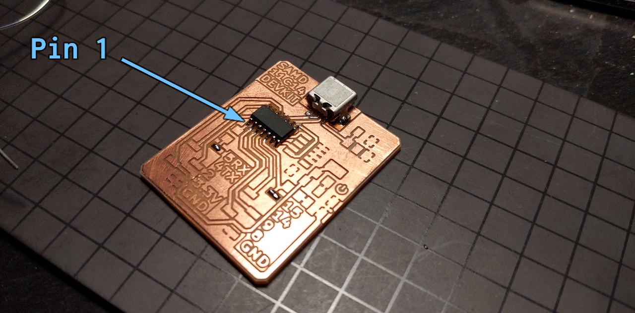
Next, I carefully examine the SAMD to figure out which orientation is the right one. You’ll notice a very small round dot at the bottom left corner when the lettering is facing upright. This indicates pin 1.

Make sure pin 1 is placed on the left of the board, as indicated here. You can secure the chip by soldering one corner pad first, then the opposite corner.
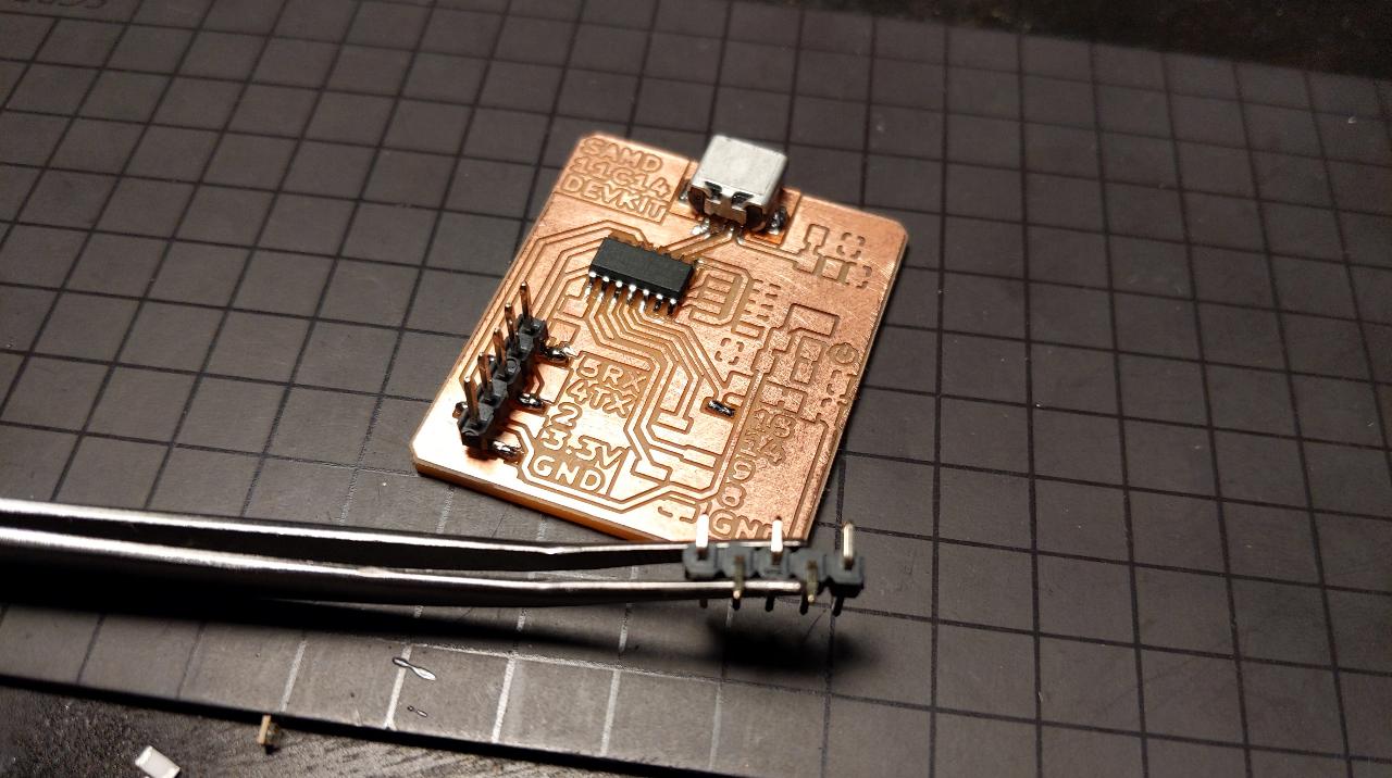
When soldering the 5x1 pin rows, make sure to put some solder on their bottom side first. I had some issues when I tried to skip this step: it seems there was a protective coating on the pins preventing the solder to form a good bond.
After adding the JTAG connector, LEDs, voltage regulator and capacitors, the board is ready for use. You can customize the LED colors, I use green for the power indicator (the upper one), and blue for the other one (connected to pin 15). I needed a 4.7~{\rm k}\Omega resistor on the blue and 680~\Omega on the green LED to reach an equivalent brightness, you might need different values.
After carefully testing the board for shorts, plug in the USB and make sure you see the power light turning on. If it doesn’t, you can test the output of the voltage regulator, it should be a steady 3.3V.
Programming
A port of the Arduino core is available for the SAMD11C. In order to use it, you must program your chip with the provided bootloader. It can then be re-programmed through the USB serial port, which is highly convenient.
You can start by downlading the sam_ba_Generic_D11C14A_SAMD11C14A.bin bootloader, as well as edbg to load the binary on the board.
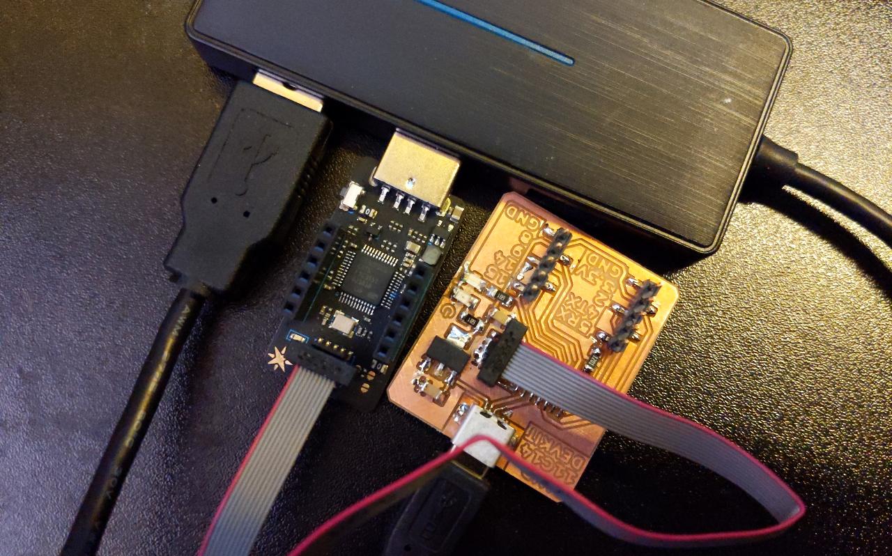
When programming the board, it is important to provide a power supply, as my connector ignores the VCC. I use a USB hub to provide power to both the programmer and my board. Make sure the JTAG connector oreintation is correct; the data line is right next to the chip, while the power line is closer to the edge’s board.
Open a terminal and run the following command to flash the device:
edbg -bpv -e -t samd11 -f sam_ba_Generic_D11C14A_SAMD11C14A.bin
Pay attention to the -e parameter, which tells edbg to completely erase the memory before starting. This makes sure any previously installed bootloader gets removed. The output of the command should look like this:
Debugger: ARM CMSIS-DAP 1093000031387d241239333437353533a5a5a5a597969906 1.10 (S)
Clock frequency: 16.0 MHz
Target: SAM D11C14A (Rev B)
Erasing...  done.
Programming................... done.
Verification................... done.
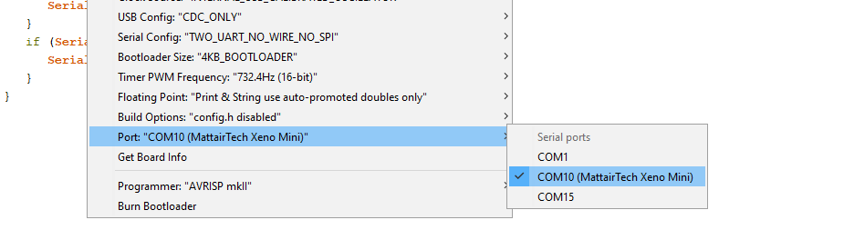
The board is now ready to use together with the Arduino software: it should appear as a serial port with the name “MattairTech Xeno Mini”.
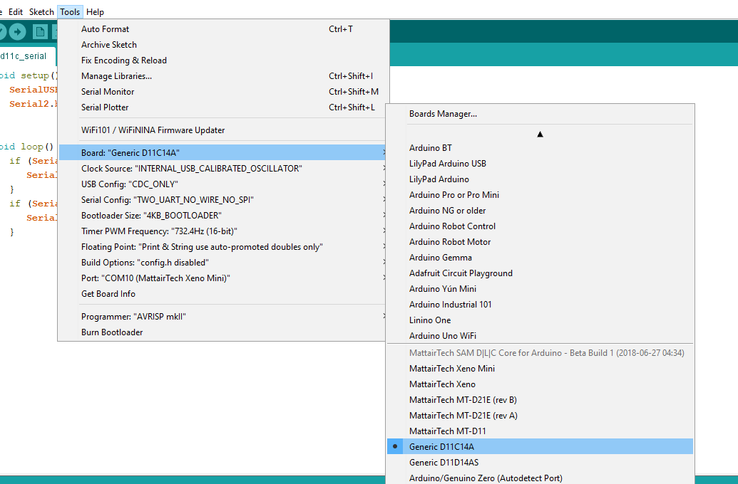
Make sure you installed the Arduino core for SAMD, and select the right type of board.
License
This project is provided under the MIT License.