SAMD11 dual serial

In this project, a SAMD11C14 is turned into a powerful dual serial-to-USB adapter. It appears as two distinct ports on the host computer and supports dynamic, independent settings of:
- baudrate
- parity bit (even/odd/none)
- stop bits (1/2)
Both ports provide 5V power to the target directly from the USB lines, and are resilient to 5V data thanks to a protection resistor on RX. The TX lines always output 3.3V logic.
Demo
Self loop
Mutual loop
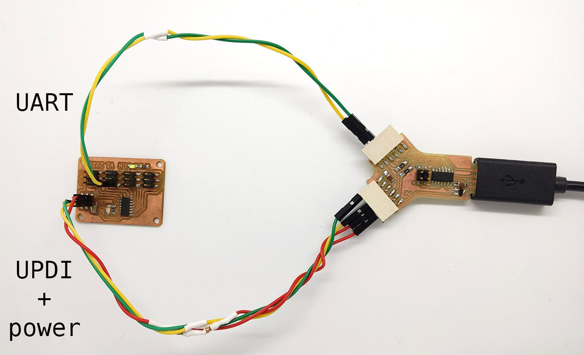
UPDI programming + serial monitoring
Design
The design is straightforward. The only challenge was finding which pins to use for the serial communication. The SAMD11C14 has two USART modules, SERCOM0 and SERCOM1. I use the following pins:
| Pin | Mux | Pad | |
|---|---|---|---|
| SERCOM1 TX | PA08 | C | 2 |
| SERCOM1 RX | PA09 | C | 3 |
| SERCOM0 TX | PA14 | C | 0 |
| SERCOM0 RX | PA15 | C | 1 |
In the following, SERCOM1 will be called port 1, and SERCOM0 port 2.
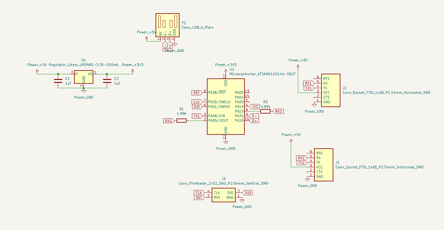
The schematic is simplified to the max. Note the 5k protection resistor on RX to make it 5V tolerant:
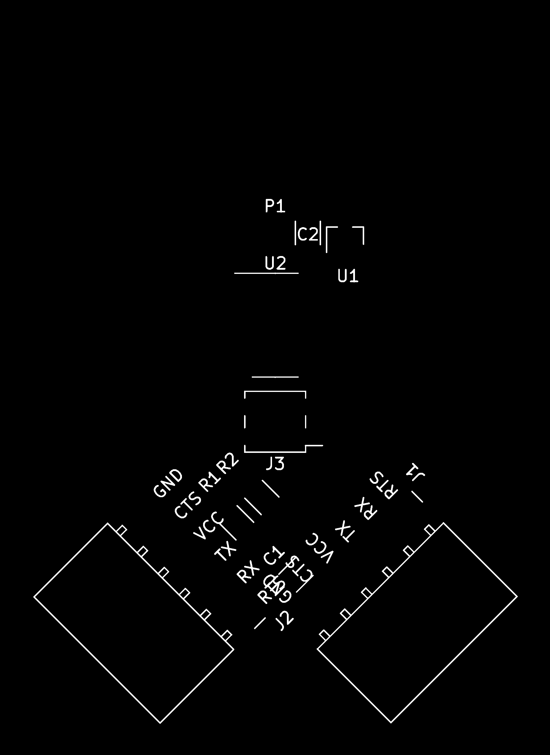
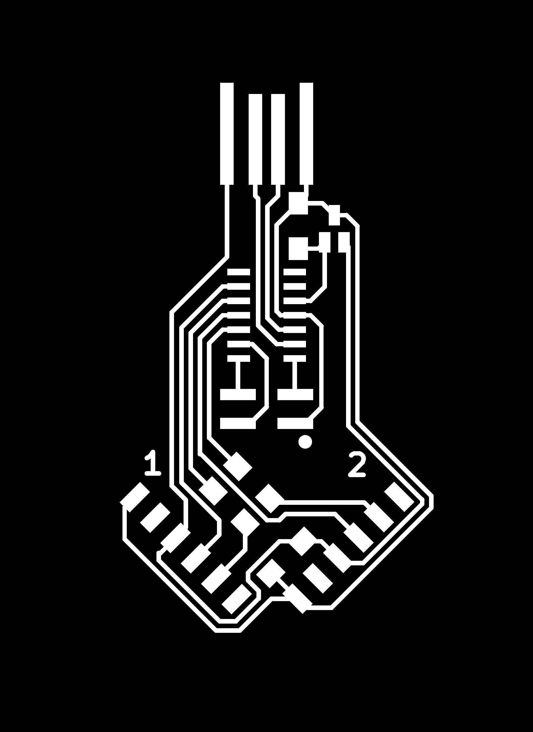
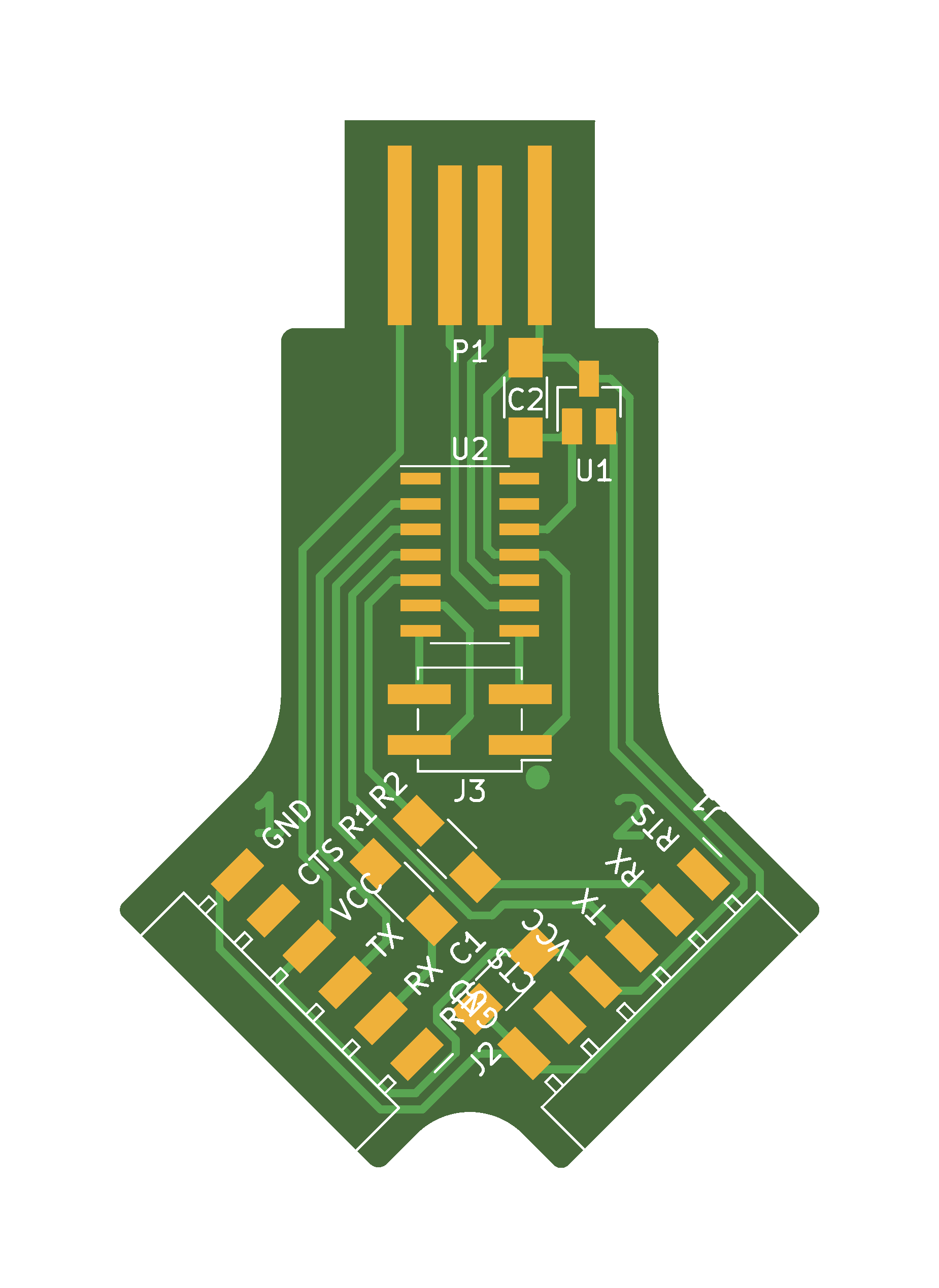
Routing is convenient thanks to the pin configuration:
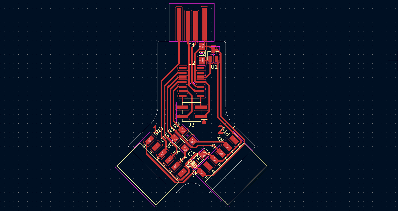
Here is the pinout of the two ports. The RTS and CTS lines are not used.

Production
This board can easily be milled with a 0.4mm flat end mill, or your favorite combination of V-bit and flat end.

After cleanup, the board is ready for soldering.
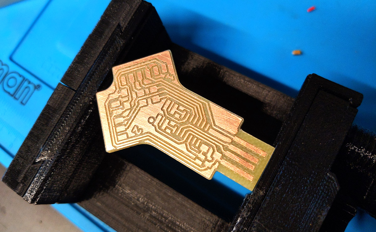
Here is the finished product. Note the port numbers on each side.
A star application is UPDI programming of an AVR target, while monitoring its serial communication on the other port (see demos). Designing a board with the D11C directly connected to an AVR chip would be pretty slick.
Firmware
The code was made with Microchip Studio 7 and makes extensive use of ASF for handling the USB protocol. The easiest is to download the compiled binary: dual_cdc_d11.bin. You can find also download the full Microchip studio project here.
You can then flash it with edbg:
edbg -ebpv -t samd11 -f dual_cdc_d11.bin
After flashing, you should see a composite CDC device with two ports. On Windows, I use the device manager to spot the COM number of each port:
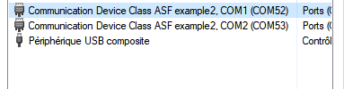
The weird port names come from the VID/PID of the composite CDC from ASF. I wish there was an easy way to change that, but it’s unclear.
License
This project is provided under the MIT License.
Downloads
Firmware
PNG files (1000 dpi)
Traces:
Interior:

Composite:
Solder mask:

Silkscreen: