5. Electronics production
This week’s assignment was centered around producing pcb with the use of a pcb milling machine. Additionally, we had the opportunity to try other pcb production methods. I focused on two tasks:
- Milling, soldering and programming a JTAG D11C programmer board
- Creating a flexible circuit with the vinyl cutter
Group assignment
In the group assignment, we tested our milling machine with a 1/64 in and 1/100 in flat end mill with good results.
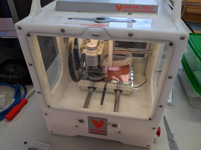
Our machine is a desktop PCB Milling Machine from Bantam tools, with a build plate of 5x4 in.
pcb milling
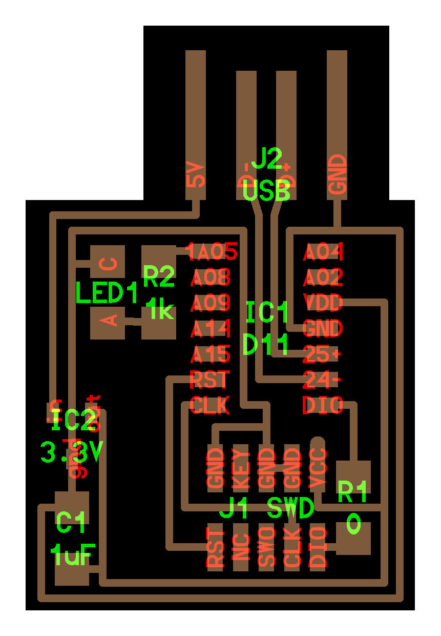
I started with the provided design for the D11C, with an LED and a single JTAG connector:
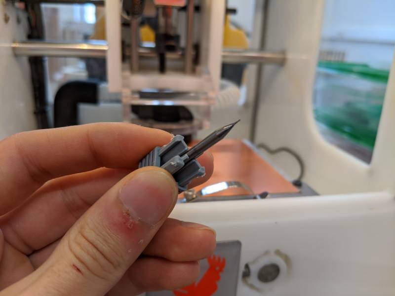
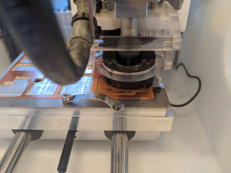
For this job, I used a 1/64 in (0.4 mm) flat end mill:
For the conversion to G-code, I followed the same procedure that was described in our group assignment. Namely, I used the G-code -> mill 2D png program in mods, and the mill raster cell was set to:
- tool diameter: 0.0156 in
- cut depth: 0.07 mm
- max depth: 0.14 mm
- offset number: 10
And for the path to G-code cell:
- cut speed: 200 mm/min
- plunge speed: 200 mm/min
- jog speed: 300 mm/min
- jog height: 2 mm
- spindle speed: 30.000 RPM
- format: mm
The milling took about 30 minutes. The outline was performed with a 1 mm tool in a single cut.
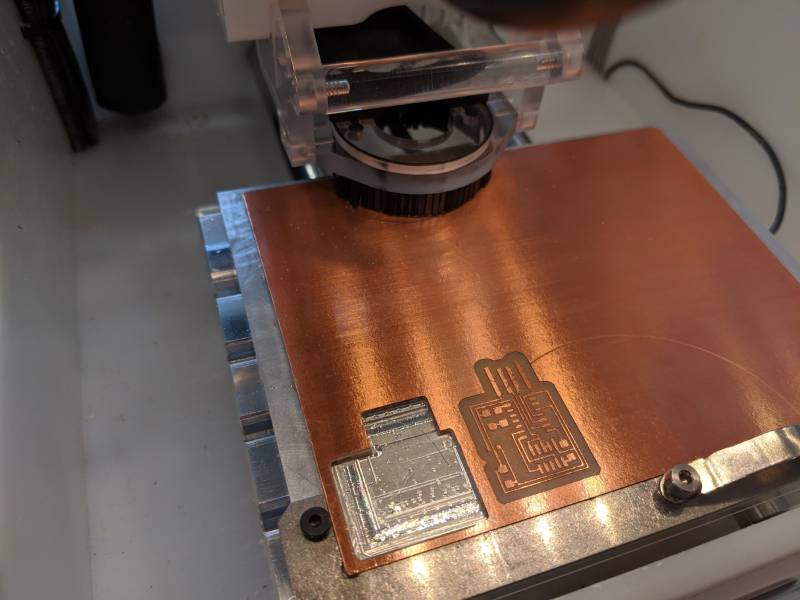
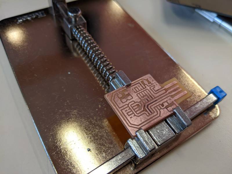
The finished product is remarkably clean, and the pads seem easy to reach for soldering.
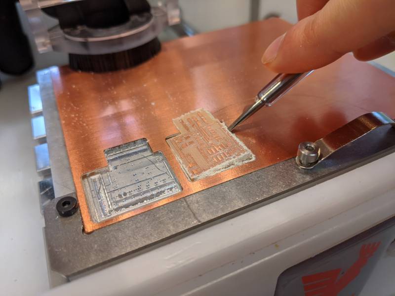
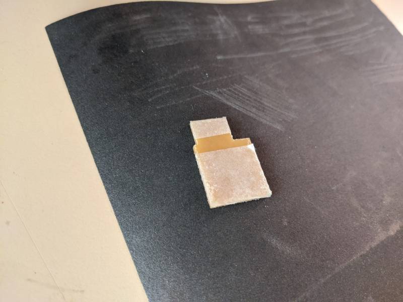
The edges of the freshly milled pcb are still a bit rough.

For the cleanup, I used water and soap to remove some of the remaining dust. I then sanded the board with a fine grit to cleanup the traces.
I could then move on to soldering the components. However, I decided to use a different design for my final pcb. The main reason is that there is only a single JTAG connector here, which means I cannot use the board as a USB to JTAG programmer; it can only be programmed through its only JTAG port to perform very simple tasks.
With the help of my fabacademy instructor, we designed a new board in EAGLE. We started with the schematic:
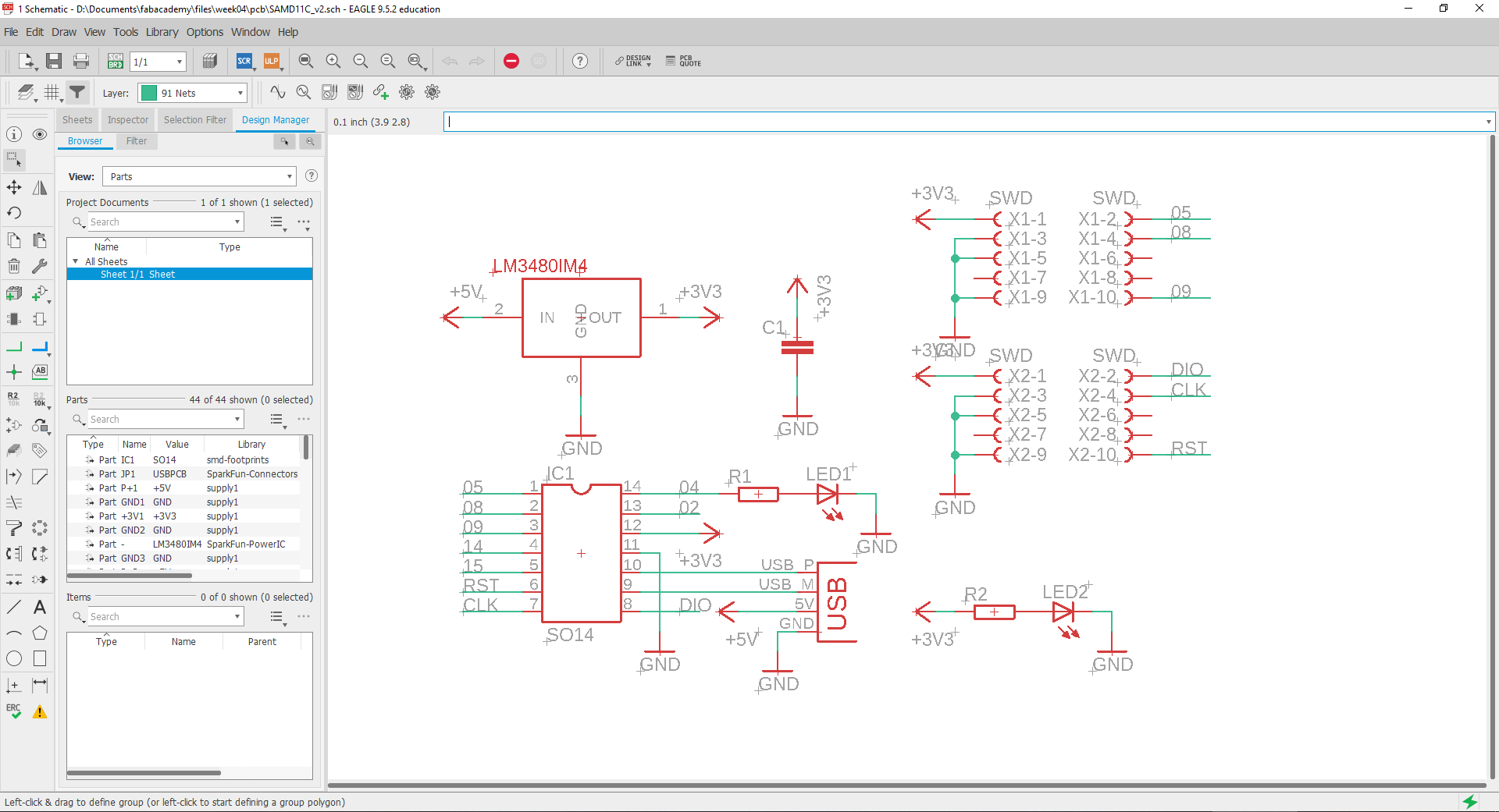
Then we placed the components on the board. The extra features offered by our modifications are:
- Two JTAG connectors
- One LED indicating power ON
- One LED on PIN 4
- A ground plane covering the whole board
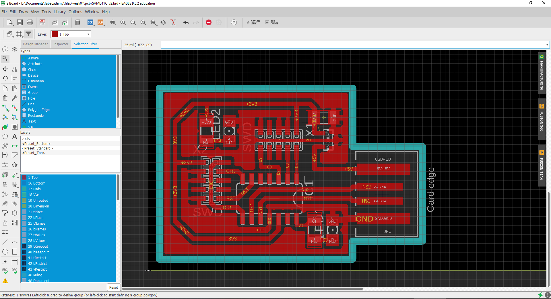
Using the board editor in EAGLE is quite straightforward. Every device from the schematic is visible as a footprint on the board. Connections are the same, but wires need to be placed manually to satisfy those connections. There is an auto-route option, but for a single layer board, best results are obtained through manual routing.
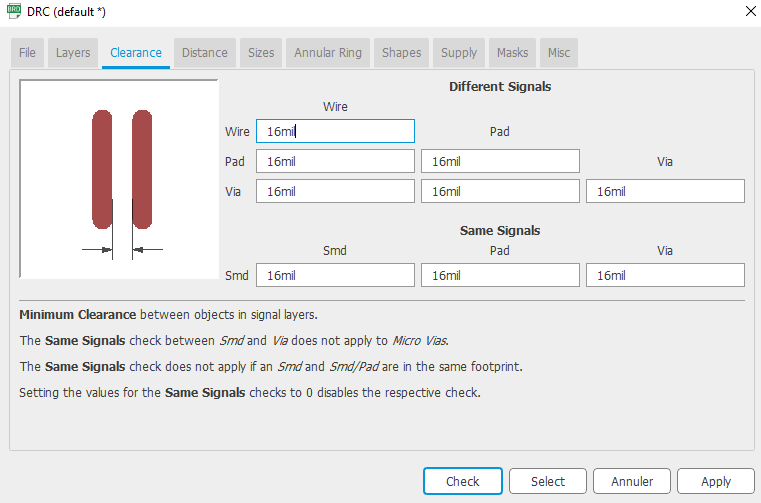
The design rules check (DRC) is a useful tool that lets you check wether your design can be produced correctly. By clicking on the DRC button on the lower-left, I get a new window where I set tolerence compatible with a 1/64 in tool:
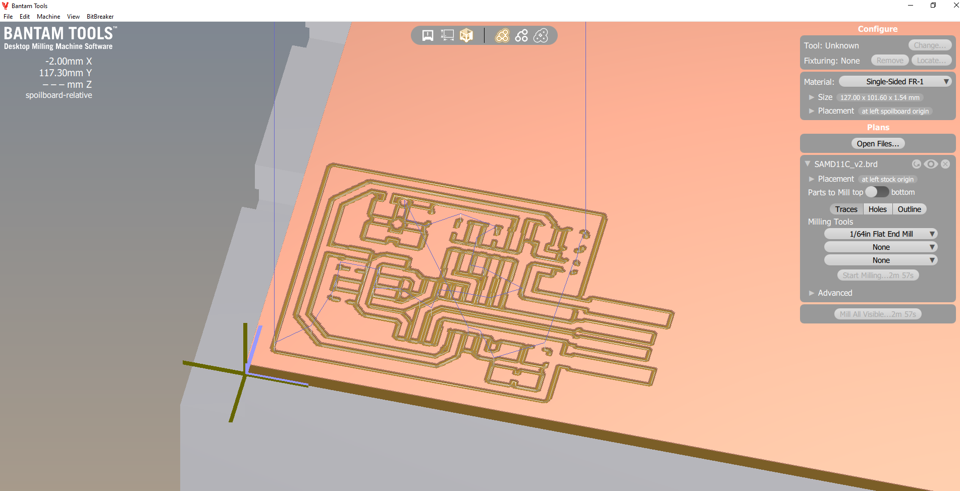
For the outline of the board, I trace a line in the milling layer. The host software from Bantam tools supports EAGLE files natively, so it was a good opportunity to try this alternative G-code conversion pipeline. I loaded the .brd file:
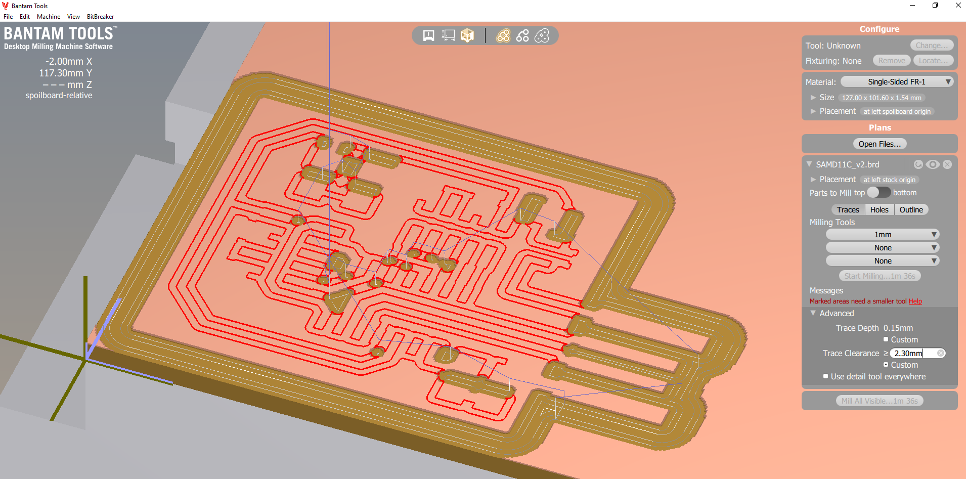
Thanks to the ground plane, the milling can be performed in only a few passes with a 1/64 in (0.4 mm) bit. However, the area near the USB port needs more clearance. I decided to add a second job with a 1 mm with a clearance of 2.3mm to clean those areas later. Even though the software is complaining that it cannot reach all areas with such a large bit, this can be safely ignored, as the 1/64 in tool already went there.
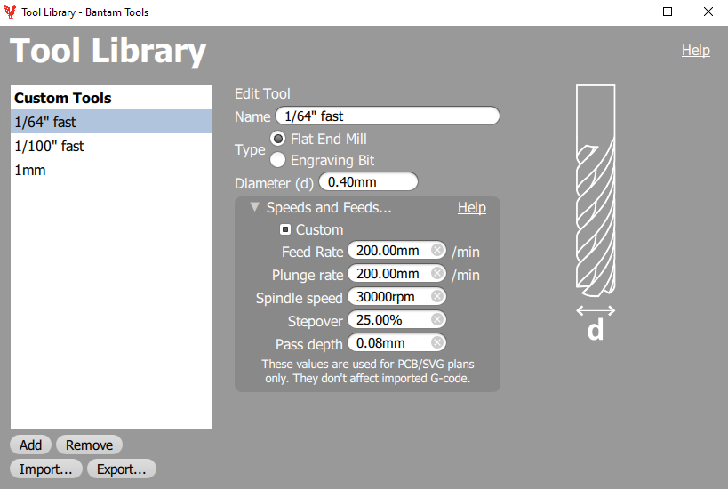
To add a new tool in the software, I click on tool library and set up the tool diameter, feed rate and max step down:
It is important to setup the correct thickness for the material. In my case, I know that the thickness of the copper plate + sticky tape is around 1.74 mm. To measure this, the BitBreaker tool can be used in the menu. The machine can detect a contact with the copper plate using a small electric current flowing through the tool itself. The BitBreaker module lets you measure the plate thickness with this method.
The milling took about 30 minutes in total, and the outline was cut with the 1 mm in a single pass.
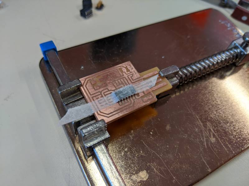
The finished pcb is slightly more challenging to solder, as the wires are sometimes very close to the ground plane. However, there was no incident during soldering.
I started by taping the D11C to make sure it wouldn’t move during soldering of its first pins. For the smaller components, I used a different method: I first solder a single contact on the raw pcb, then bring the component in place with a set of pliers while heating its pin with the soldering iron. Both methods were effective.
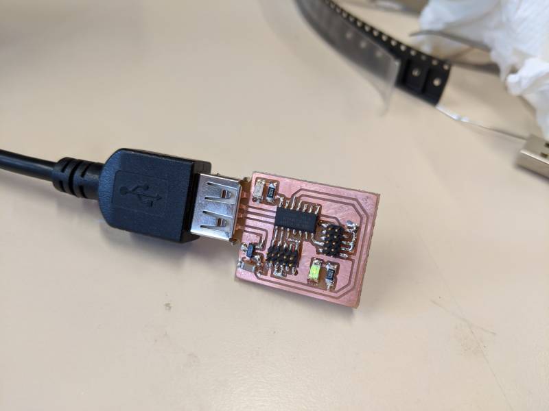
The finished product is relatively clean. I can immediately connect it to a USB port to see if the power ON LED does its job correctly.
D11C programming
We used a particle.io JTAG programmer to initially flash the bootloader to our D11C chip.
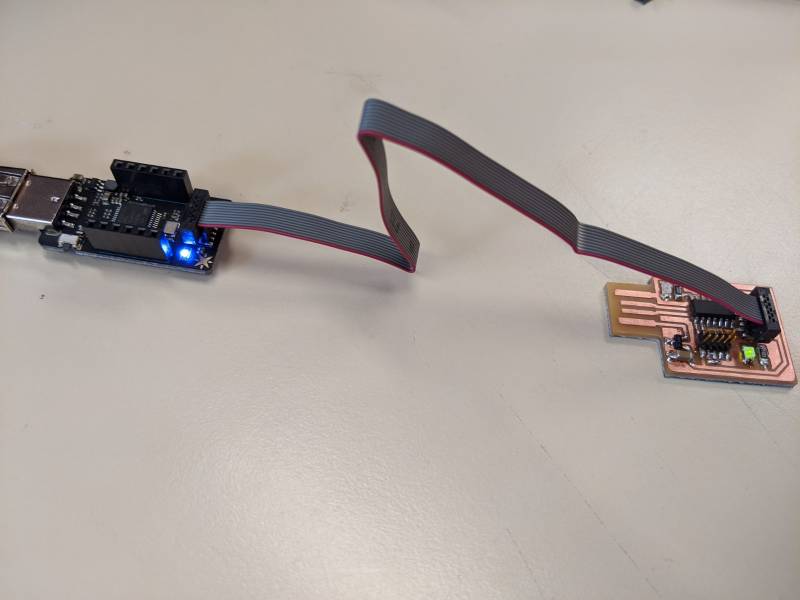
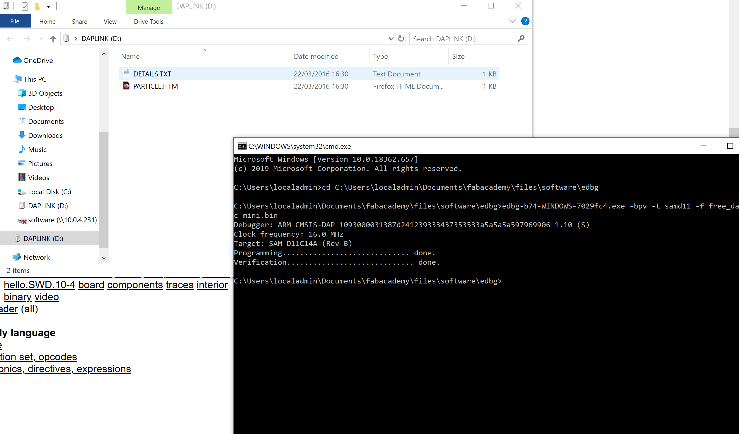
We used EDBG with the provided binary file free_dap_d11c_mini.bin. Programming occured correctly, indicating that my D11C was correctly connected to the JTAG pins.
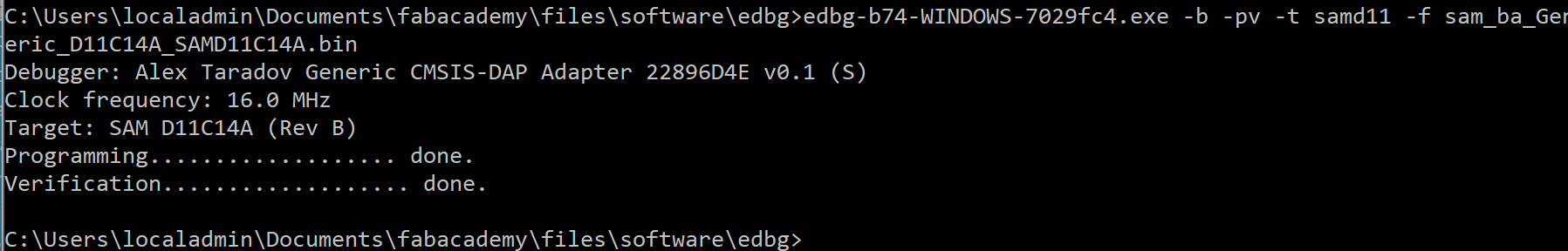
To prove that the binary file was correctly functioning, I connected the chip directly on my USB port, and used it to program another board through its outgoing JTAG connector.
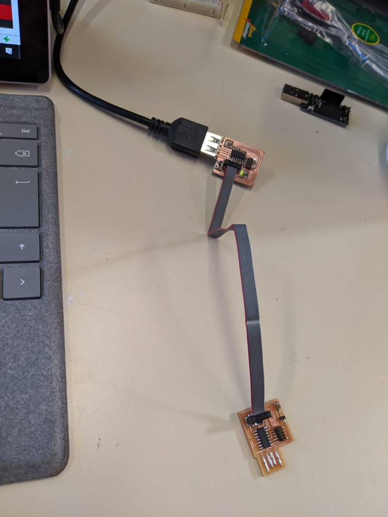
My board was able to communicate with EDBG and program the other board correctly, which was a huge relief. In the coming weeks, I will try to program my board to perform different tasks, such as blinking the LED, or directly program it through USB which should be feasible with the correct bootloader and a modified Arduino IDE.
Flexible circuit
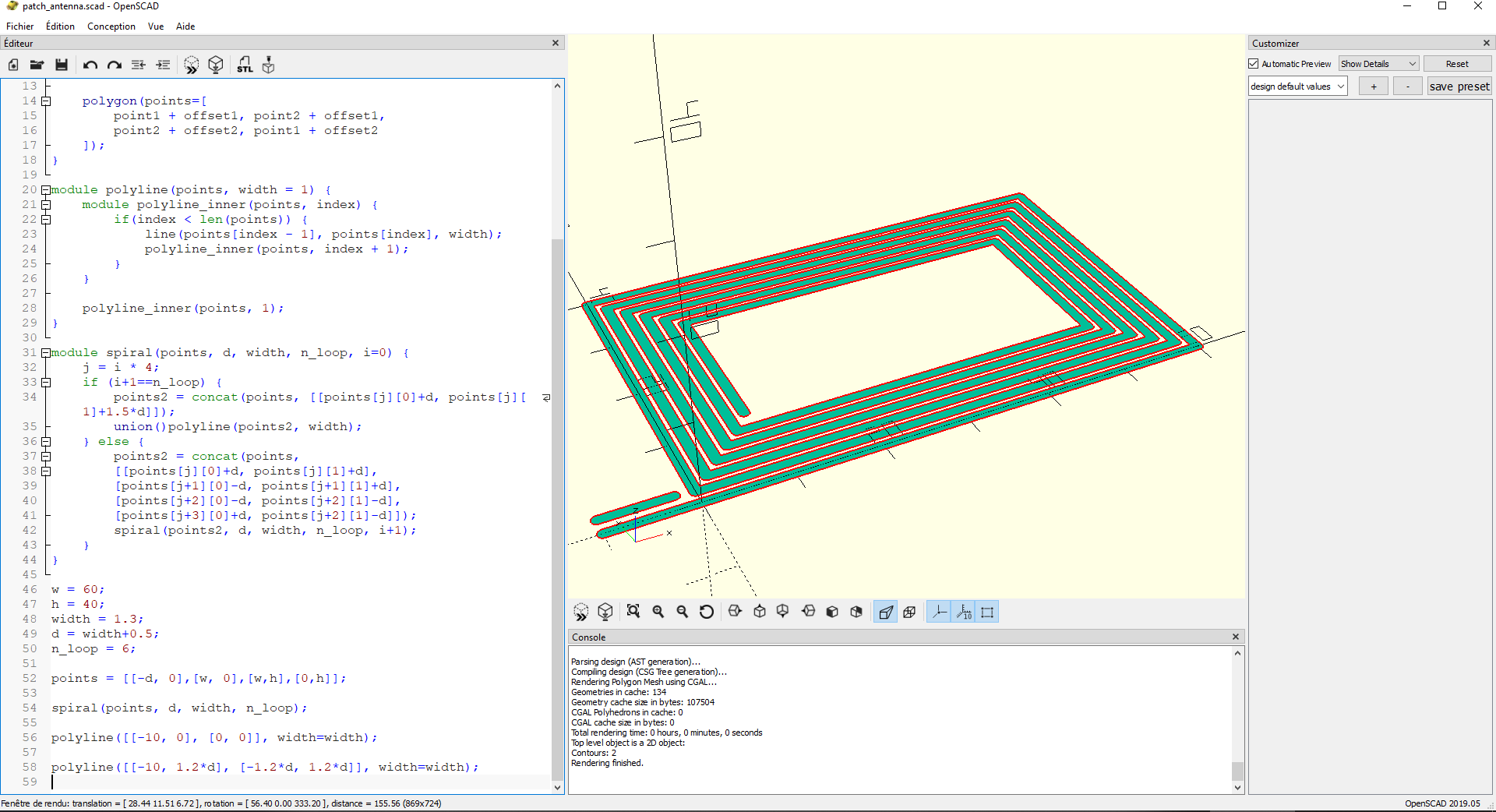
As I had a bit of extra time this week, I was curious to see how the vinyl cutter could be used to cut a flexible circuit. For my design, I went for a patch antenna, which have become very popular with NFC tags, anti-theft devices and Qi charging.
As a I wanted a parametric number of loops, wire width and clearance, I wrote a module in OpenSCAD to place the spiral points, and connect them to form a poly-line with rounded edge thanks to a module I found online.
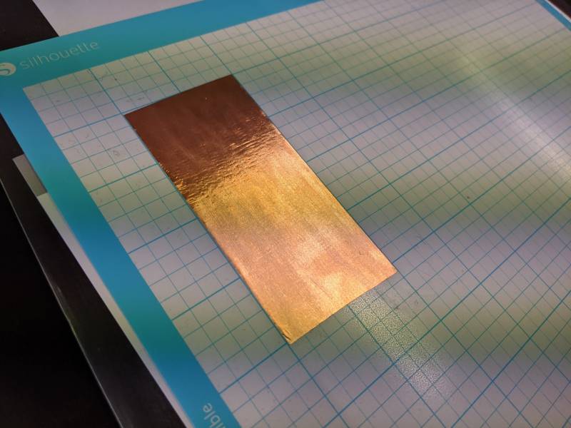
I found some copper tape with a protective paper on the back, and sticked the whole thing to the Silhouette Cameo’s cutting plate.
On the first try, I used the following settings:
- Depth: 2
- Speed: 6
- Force: 10
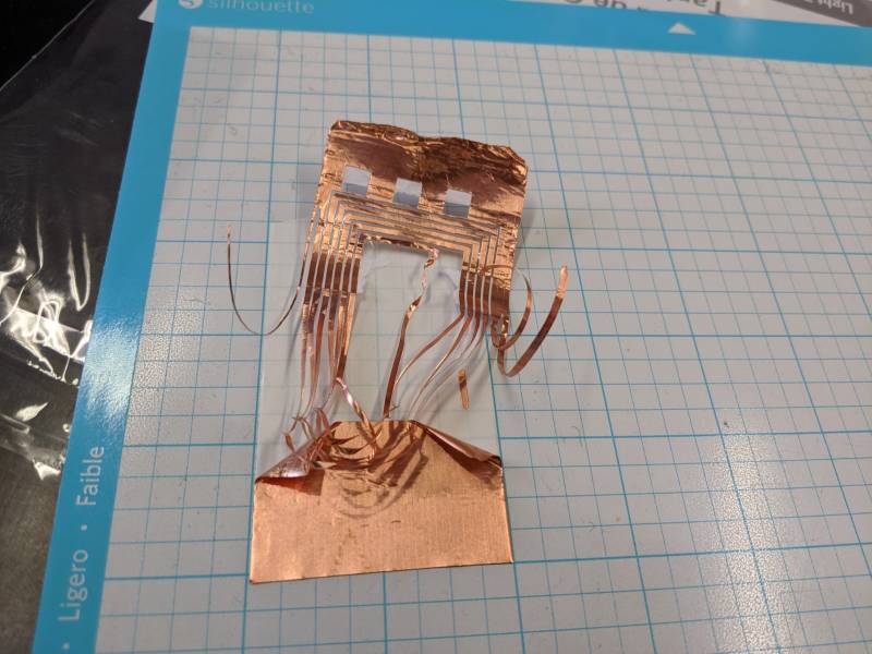
However, peeling off the unwanted copper resulted in a failure. The main reason was that the cuts were perfect.
I then decreased the speed, and increased the force a bit:
- Depth: 2
- Speed: 2
- Force: 16
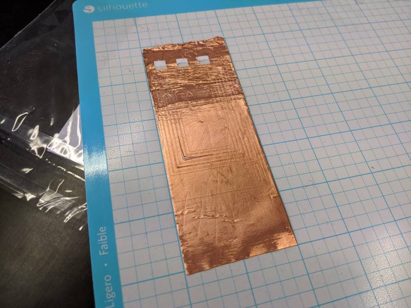
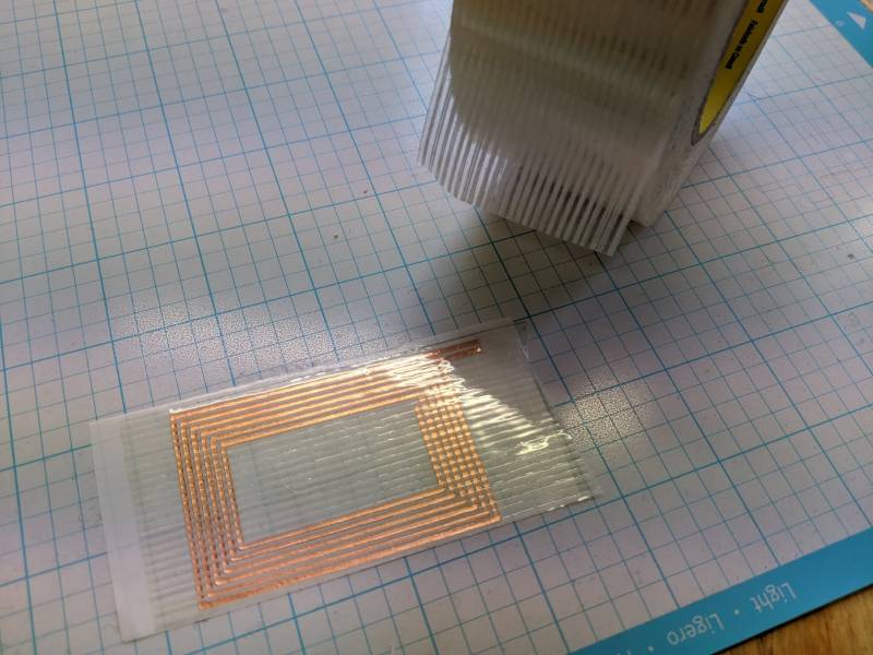
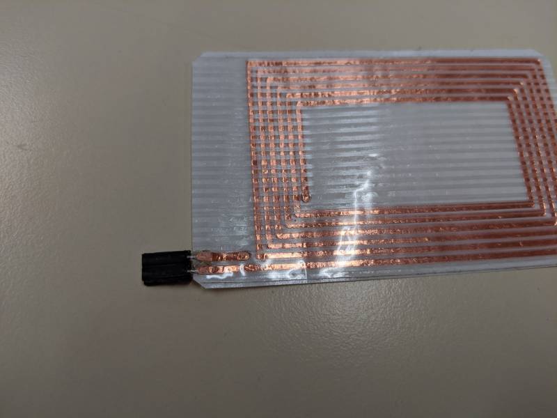
Peeling off the extra copper was a success.
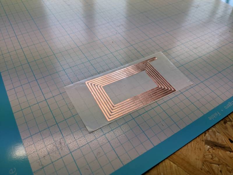
I immediately taped the remaining copper in place to protect it from falling appart. While the protective paper on the back was not the greatest surface to place my antenna, it was good enough for this test.
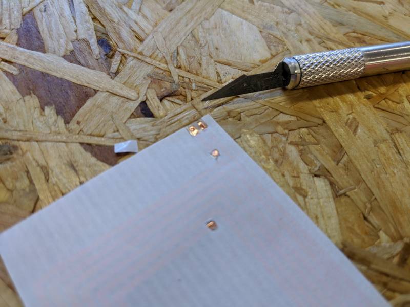
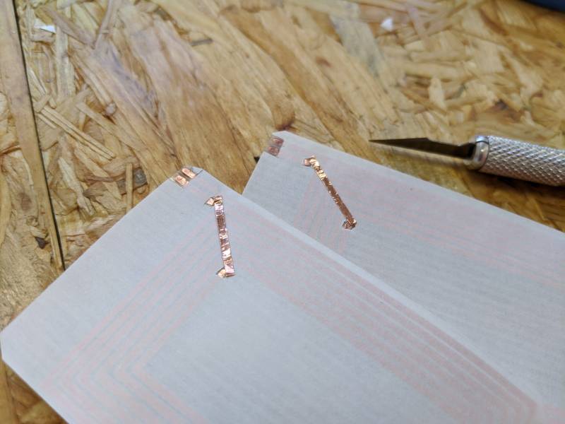
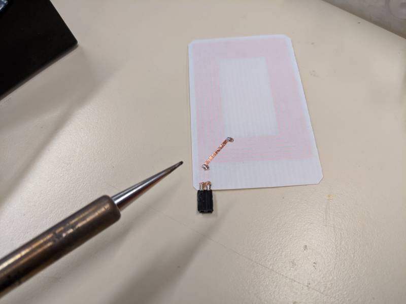
To close the circuit and adda connector, I used a small cutting knife to reveal the relevant areas. There was a bit of glue on the copper, which I scraped off.
I completed the circuit with an extra band of copper from my initial failed test.
Soldering the connector and the extra band was a bit challenging, as the heat threated to melt the plastic on the back side. I had to be quick in the process.
The finished product is usable. I was able to transmit a pretty weak signal between two of these antennas with a 27 MHz sine wave. In the coming weeks I will try to show how RFID tags work, by first charging a capacitor with a diode bridge, and then discharging the current in an LED for instance.
With a quick calculation, I estimated the inductance to be of only 4 µH, so I doubt this design could be used to transmit any serious power. I might need to add a few loops, or use several antennas in series. This was still a satisfying result for my first flexible circuit.