Individual Assignment
Make and test the development board that you designed to interact and communicate with an embedded microcontroller.
Group Assignment
Characterize the design rules for your in-house PCB production process: document feeds, speeds, plunge rate, depth of cut (traces and outline) and tooling.
Document your work to the group work page and reflect on your individual page what you learned
Learning outcomes
- Described the process of tool-path generation, milling, stuffing, de-bugging and programming
- Demonstrate correct workflows and identify areas for improvement if required
Make and test the development board that you designed to interact and communicate with an embedded microcontroller.
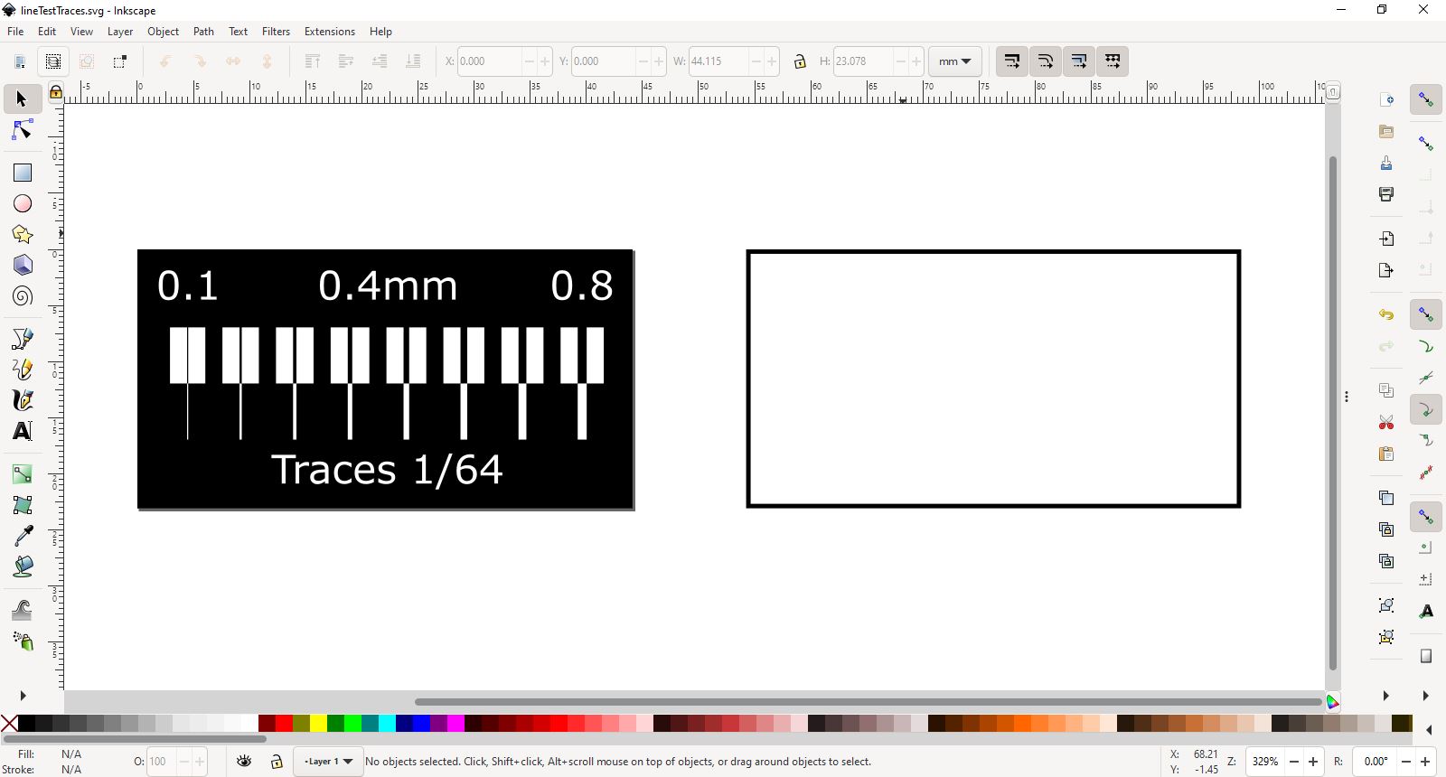
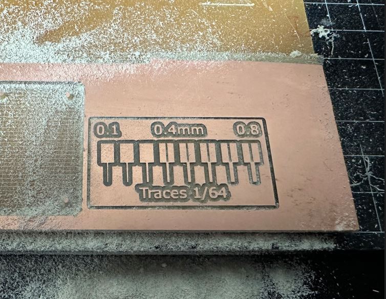
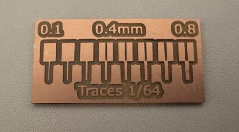
I started this week by making a simple line test to see how our milling machine performs. I milled the board using Fab Lab Reykjavik´s Roland MDX-20. We use an old version of Mods to send our design to the mill. The software is run on a raspberry pi and I can access the software through our local network. All lines 0.4mm and above were milled just fine, everything below 0.4mm did not mill. All trace widths look fine, including the finest trace width of 0.1mm.
Line test Inkscape
Line test milling prep
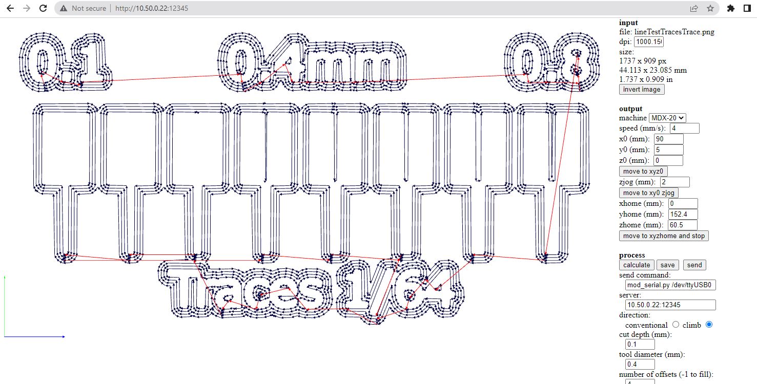
To mill boards using the Modela MDX-20 you need to prepare the machine. First you need the correct milling bit, I´v been using 1/64 in bit for trace milling and 1/32 for through-milling. To change the milling bits I use the UP arrow on the machine to raise the miling bit and collet. Once the bit is in top position I remove the bit using a hex bit and replace with the correct milling bit. When the correct milling bit is in place I lower the bit using the DOWN arrow button on the machine until it nearly touches the PCB. Then I loosen the collet and make sure it touches the PCB and tighten again. That way the Z-height has been set. Setting the X and Y position is done in browser in the mods software. Under Output I type in the X and Y coordinates and hit the "move to XYZ jog" button to move the milling bit to the correct position. Now a new milling bit is ready and XYZ positions are zeroed.
Xiao board with one LED and a button
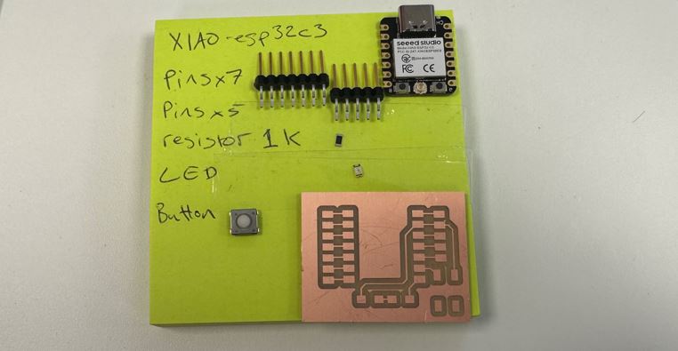
This week I wanted to make my XIAO board I made in Electronics Design Week. It´s a simple design, a XIAO board with 12 pins, a LED and a Button.
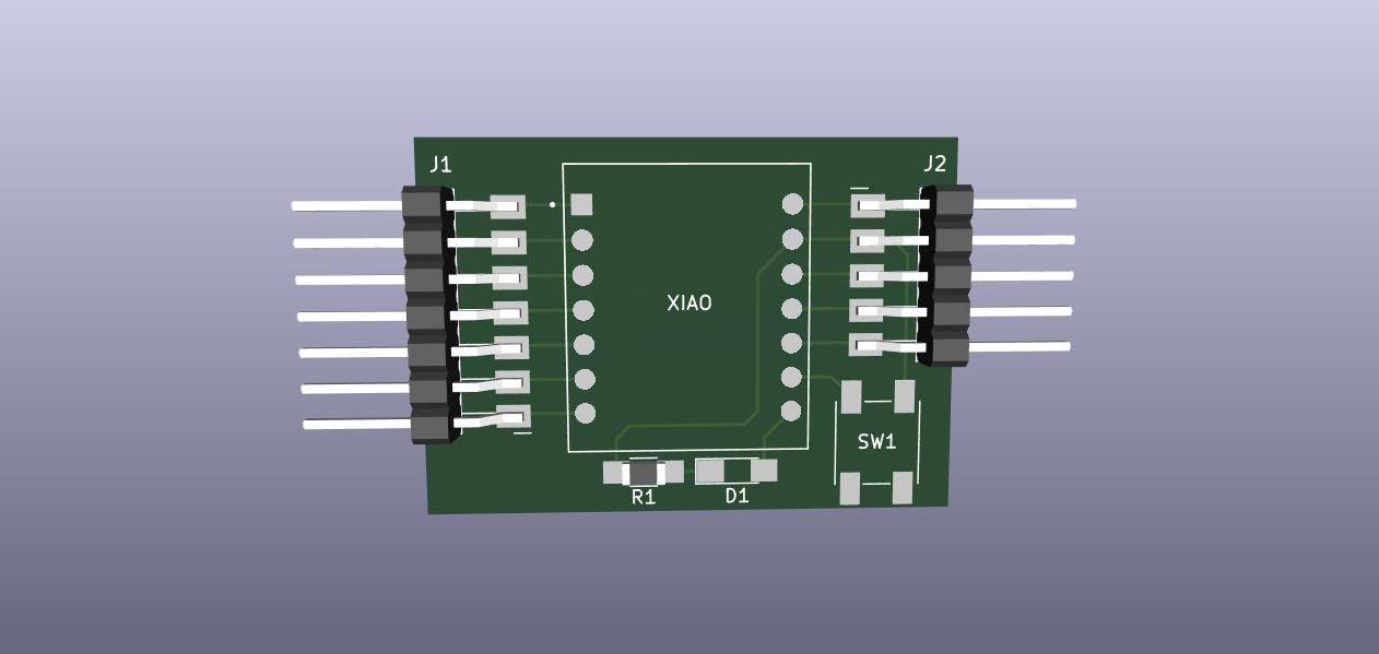
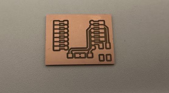
I milled the board and when I wanted to start soldering I noticed that the footprints I used were an exact fit for through-holes, so there was no overflow to the sides to solder to. I edited the .png file in Inkscape and made slightly bigger footprints so I could solder the Xiao to the milled board.
Too small footprints for the Xiao
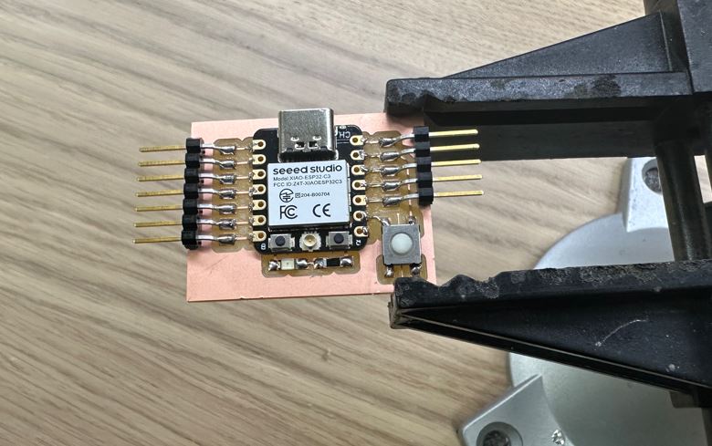
v2 with bigger footprints ready for soldering
I soldered each component and tested with a multimeter to make sure there was no bridging. Everything seemed to work fine.
I plugged the board to my computer and loaded a simple sketch to the board using Arduino IDE. The sketch comiled and loaded but the button was not working as expected. I thougth that maybe the code was wrong so I adjusted the code a bit and tried uploading again. This time the code did not want to load onto the board and I got an error message I´ve seen before. To fix the board I had to re-flash the board using this software recommended by my instructor Árni.
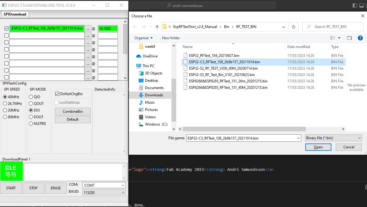
To use the software open the Flash Download tool - select your chip type ( in my case esp32-c3, Workmode: Development, LoadMode: USB. Then the click the three dots on the top line to select your .bin file. browse to EspRFTestTool_v2.8_Manual\Bin\RF_TEST_BIN folder and find your .bin file. In my case it was ESP32-C3_RFTest_108_2b9b157_20211014.bin. Then simply press the START button and your board should be fixed and able to receive code again.
I tried once more to upload a simple blink sketch to see if I could at least get the LED to blink. But my LED just stays lit, no blinking!. I wanted to spend more time this week on soldering so I decided to move on to another project. I´ll come back to this board later and try to figure out what´s wrong with it.
Update
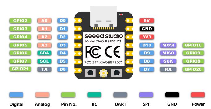
After troubleshooting I figured out the problem. I was simply using the wrong pin numbers. Using the following image you can see the pinouts for the Xiao esp32c3. For the button I was using pin 8 in my code and the button was working. For the LED I was using pin 7. The button was working but not the LED. I found out that I should have been using the green pin numbers and not the blue Digital pin numbers, or GPIO8 for the button and GPIO20 for the LED. It turns out that the green GPIO8 is also numbered 8 in the blue digital pins, so that is why the button worked. So, to make everything work together I simply changed the button pin to be GPIO8 and the LED to be GPIO20. And it works!
ATtiny412 board with one LED and a button
I´ve used ATtiny 44 before but never the 412 and I wanted to try it because it´s nice only needing three pins to upload code. I had designed a small board with an ATtiny 412 a LED and a button using SVGPCB in Electronics Design Week and decided to go for it. I downloaded the .png, brought it into Inkscape and made the board perimiter as small as I could and made the exterior cut file as well.
I soldered everything together and tested each trace with a multimeter to detect bridging. Everything seemed fine.
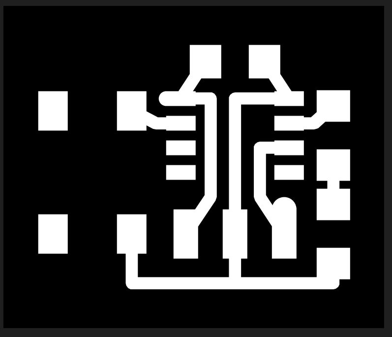
To put code onto the tiny 412 my instructor Árni. pointed me towards the serial UPDI-3 pin board. You can find the design under in-system development in Embedded Programming week. I also found the board on the SVGPCB website under examples. See here.
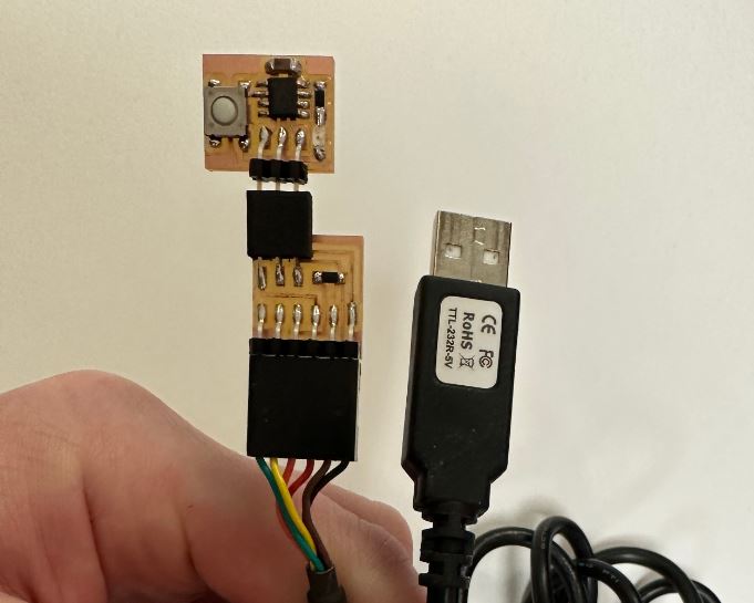
I milled the serial UPDI 3-pin board and tested with a multimeter. Everything seemed fine. So using an USB - FTDI cable I plugged it into the Serial UPDI 3-pin board and plugged my ATtiny412 board to that. Following the instructions on Árnis site I was able to upload code to my board.
But I was only able to get the LED to blink without using the button. The button was not working!
After some back and forth with my instructor, Árni pointed out that I should take a better look at the button with a multimeter. It was then I realized that the button needs to be rotated 90 degrees. The way the button was oriented it was not doing anything, it was basically just a bridge. So I went back into Inkscape and rotated the footprints for the button and milled again.
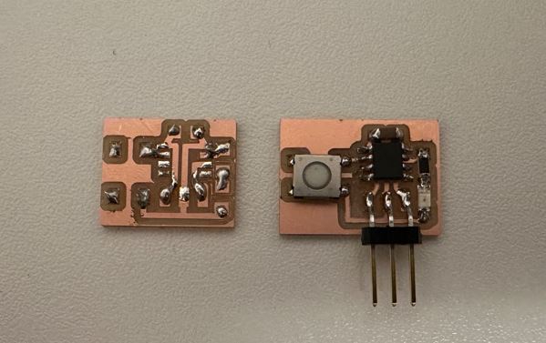
I was able to remove all the components from my first board and successfully solder them to my v2.
I plugged it back to the UPDI 3-pin board and FTDI cable, and using Arduino IDE I uploaded a simple code that controls the LED with the button. One press turns the LED on, two presses turns it off, three presses blinks the LED three times and four blinks the LED randomly.
It works!
Group Assignment
Characterize the design rules for your in-house PCB production process: document feeds, speeds, plunge rate, depth of cut (traces and outline) and tooling.
For our group project me and Hafey went over the design process for our in-house PCB production process. Link to group assignment.
I am familiar with an old version of Mods to mill pcb boards and went over the process with Hafey.
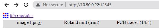
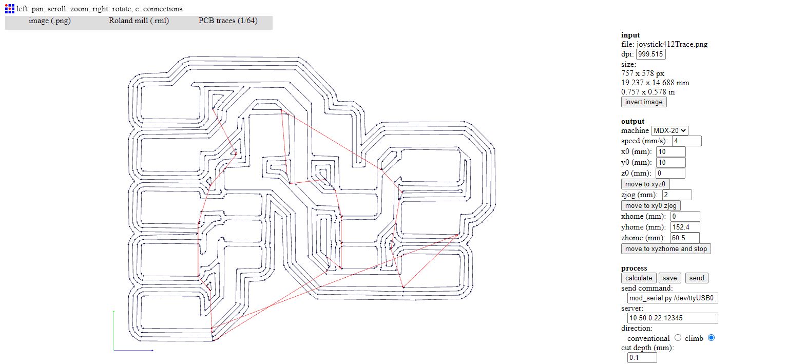
Fab modules is run loacally on a raspberry Pi that is connected to the Roland Modela MDX-20. We access fab modules through the local network, in this case by going to a browser and visiting (ip address: port) 10.50.0.22:12345 In fab modules we start by selecting the input format, I always use the image(.png) option. Then you need to select the output format, in my case I select Roland mill (.rml). Finally we select the process, to mill the circuit we use PCB traces (1/64), to cut the outline of the board and through holes we select PCB outline (1/32).
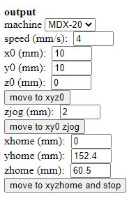
On the right hand side of the browser you can mess with the settings for the mill. Start by selecting the machine under output. In my case I select MDX-20. Under output you can see the speed mm/s and the xyz position of the machine. I have been using the default 4 mm/s for the speed. You can input new coordinates for the xyz position and hit the move to xyz0 button. But before hitting the move to xyz0 button you need to go under process and make sure the server field is correct, in my case it should read 10.50.0.22:12345.
Output
Process
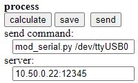
Under process are more settings to consider. Cut depth (mm) is set to 0.1. If the the traces do not mill through the copper make sure that the z axis is properly set and that the board is properly fixed. Then try again with cut depth(mm) at 0.1. If the traces are still not going through the copper you can put the cut depth to 0.11 - 0.13 and you should definitely get through the copper. The next setting is tool diameter(mm). The 1/64 milling bit is about 0.4mm in diameter so I usually keep it at 0.4mm. However, if you have very tight traces, less than 0.4mm you can edit this field to "fool" the machine into milling tight traces. I´ve successfully milled traces that are 0.3mm wide using a 0.4mm milling bit by editing the tool diameter field to 0.3 and hit the calculate button to see if the trace visualization changes. The rest of the settings I usually just keep at default. When you are done with the settings you hit the calculate button to visualize the milling process and finally hitting the send button will start the milling.
Trace calculated
To drill holes or cut through the board I open a new browser window and go to the ip address: port, 10.50.0.22:12345. I select the same input format and output format as before but under process I select PCB outline (1/32). The settings for the outline process are very similar to the settings for the traces process. The main difference is that the cut depth is set to 0.6mm per pass, and you can input the material thickness.
Outline (cut through) calculated
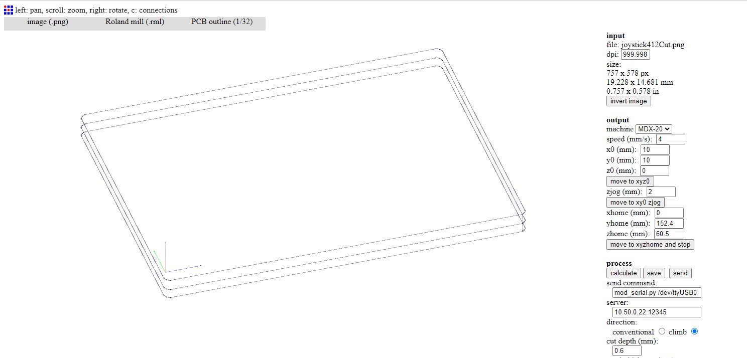
When you are done with the settings you hit the calculate button to visualize the milling process and finally hitting the send button will start the milling.
I have played around with two sided milling. When milling two sides you simply mill the traces on the top side and then cut through all holes and then cut the edge shape of the board. Then for the bottom side you simply take out the board, flip it and place it back in the machine, just make sure to place the board as accurately as possible in the same place. Then you mill the traces on the bottom side.