Individual Assignment
Add an output device to a microcontroller board you've designed, and program it to do something.
Group Assignment
Measure the power consumption of an output device
Document your work on the group work page and reflect on your individual page what you learned.
Learning outcomes
- Demonstrate workflows used in controlling an output device(s) with MCU board you have designed.
Add an output device to a microcontroller board you've designed, and program it to do something.
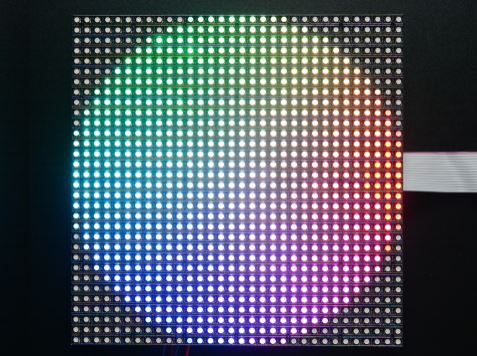
For my final project I plan on making an arcade machine. I will be using a 32x32 RGB LED matrix for the screen. Here you can see the LED matrix I purchased from Adafruit.
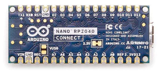
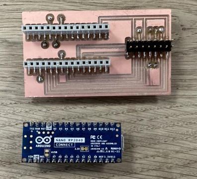
The LED matrix has 16 pins that need to be connected so the XIAO boards I´ve been using will not work since they do not have enough pins. I do have an Arduino Nano RP2040 Connect which has 30 pins that should do the trick. Or at least that´s what I thought. More on that later.
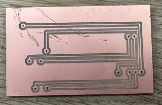
I did not want to connect all 16 pins with jumper cables so I decided to make a type of shield where I could place my Nano board and route the connections to pin headers in which the matrix cable would be plugged into. I already had female header footprints for a Nano board and also the male pin headers I needed in an Inkscape project so I copied the footprints into a new Inkscape project and routed all the connections.
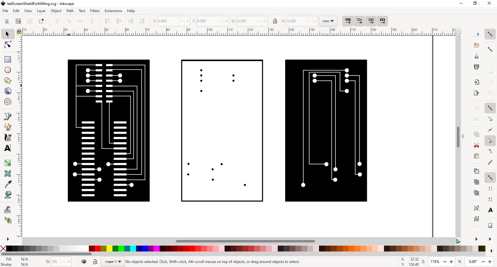
I did not want to use 0 ohm resistors as jumpers so I decided to use a double sided pcb and use vias to connect each side. My first attempt looked promising. Everything milled perfectly and I connected the sides with hollow copper rivets and punched them flat. I tested all the connections with a multimeter and all the vias and routings were perfect.
Led Matrix shield front v1
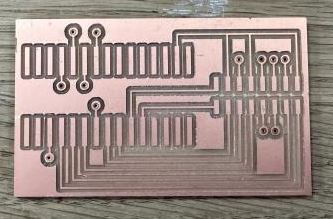
Led Matrix shield back v1
I started placing the headers on the board and they looked fine, so I popped the headers on my Nano and the matrix cable and that is when I noticed the width of the plastic on the cable was too big. The footprints were too close!
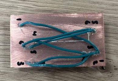
But fortunately that was a quick fix, I just moved the footprints a bit and milled again. The front milled just fine, but when I started milling the back side I guess I zeroed the Z-axis a bit off and the milling bit dragged across the board which would cut some of the routings. So I canceled the milling for the back side and fixed the problem by wiring the back side with jumpers. Not the pretties sight but it worked. I soldered the female and male headers and everything looked promising.
Led Matrix shield front v2
Led Matrix shield back v2
Now I was finnaly ready to start coding the Nano and test the led matrix. I found some example code online and tried compiling but ran into errors. I had noticed on the Adafruit a warning about the library only working on certain boards but for some reason I ignored those warnings.

According to this I needed one of these boards and the only board I had at my disposal was an Arduino Mega 2560. This time before doing anything I plugged the board into my computer and tested to see if the code would compile, which it did. And since I was running out of time for the week I just plugged everything together with jumper wires. It wasn´t pretty but it worked.
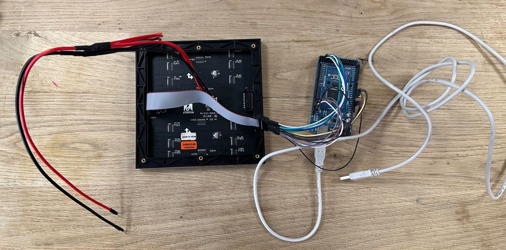
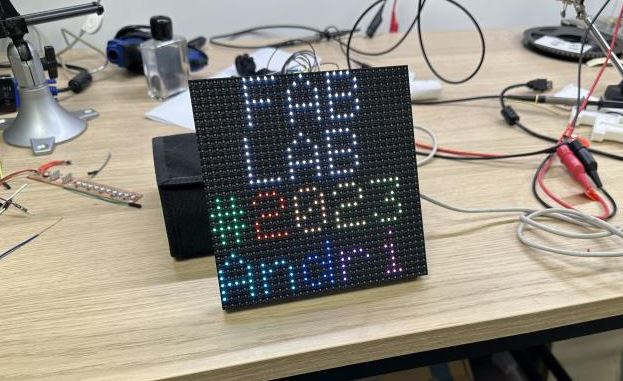
I was able to see the matrix light up. To my surprise it even lit up partly without connecting the 5v power wires. It showed most colors but not blues. So, just to make sure the screen was working properly I connected the power wires to a power supply.
The LED matrix lit up perfectly, I tested a few code examples with animations and text.
The animations were a bit choppy so I guess I need a faster board.
I played around and edited one of the code examples.
I know this does not exactly meet the requirements for the individual assignment this week but at least I know the matrix works and how to move forward. My lab does not have any ATMega2560 chips but we do have a few ATMega 16xx something chips that I may be able to use but I need to do some research. I also dove a bit deeper and apparently I may be able to use the Nano RP2040 but with a different library and using MicroPython. I need to do some more research and figure out how I can light up the matrix using a different board than the Arduino Mega 2560.
Group Assignment
Measure the power consumption of an output device
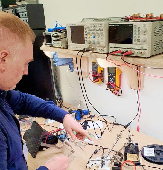
For our group project me and Hafey measured the power consumption of a SSD1306 OLED display.
We used a multimeter and started by measuring the volts.
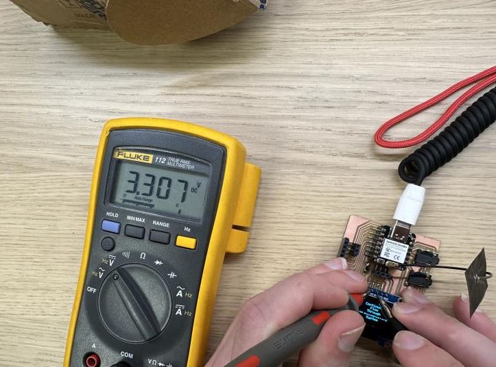
We put the probes from the multimeter on VCC and GND on the SSD1306 OLED display. We got a reading of 3.3 volts which makes perfect sense as the OLED is connected to the 3.3v output from the XIAO.
Next we measured the amps.
We wired the display to the GND, SDA and SCL but interrupted the wiring from VCC with the multimeter in between.
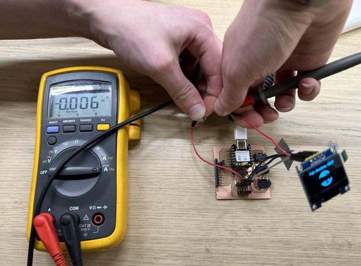
We got a reading of 0.006 Amps or 6mA.
Using this formula: P = V x I, we calculate the power consumption of the OLED
P = 3.3
V = 0.006
I = P * V = 0.0198W