Assignment
Cut something on the vinylcutter
Design, lasercut, and document a parametric construction kit, accounting for the lasercutter kerf, which can be assembled in multiple ways, and for extra credit include elements that aren't flat
Learning outcomes
- Demonstrate and describe parametric 2D modelling processes.
- Identify and explain processes involved in using the laser cutter.
- Develop, evaluate and construct a parametric construction kit.
- Identify and explain processes involved in using the vinyl cutter.
Vinyl cutter
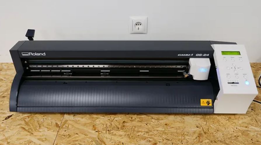
Fab Lab Reykjavik has two vinyl cutters, Roland GX-24 and Roland GS-24. For my assignment I used the Roland GS-24.
- Model: Roland GS-24
- Acceptable media: 50 - 700 mm (2 to 27.5 in.)
- Max. material thickness: 1 mm (0.039 in)
- Max. cutting area: Width: 584 mm (22.9 in.) - Length: 25 m (984 in.)
- Cutting speed: 10 - 500 mm/sec (4 in to 19.69 in/s) (all directions)
Cut something on the vinyl cutter
Working at a Fab Lab I have created multiple vinyl stickers, text labels, laptop stickers, multi-colored layered stickers and more. You can see some examples of previous work in my About Me page.
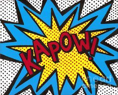
For this week I wanted to make a sticker in an art style I have wanted to try for a while. Ben-Day dots was originally a printing technique using small dots of color to create effects of shading inexpensively. I wanted to try and recreate this effect using the vinyl cutter.
Ben-Day dots inspiration
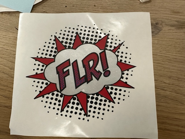
I created a multi-colored layered design in Inkscape with the letters FLR!, for Fab Lab Reykjavik and exported each layer for the vinyl cutter.
The cloud was made using the circle tool and making many large circles and using the Union tool to combine them into the cloud. For the black dots in the background I found a circular design online and used the Trace Bitmap tool to convert into vector form. I found a comic book font online and used that for the text. The triangle flame stuff behind the cloud was made using the star tool with 12 corners and a little bit of randomization. Then it was a matter of arranging everything and using the Difference tool to cut each layer into shape.
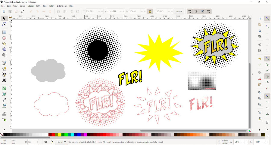
Final design

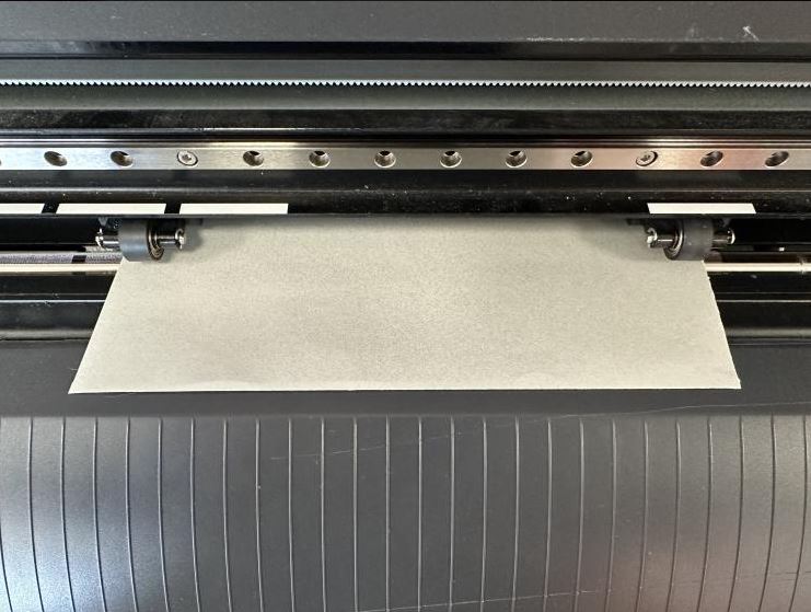
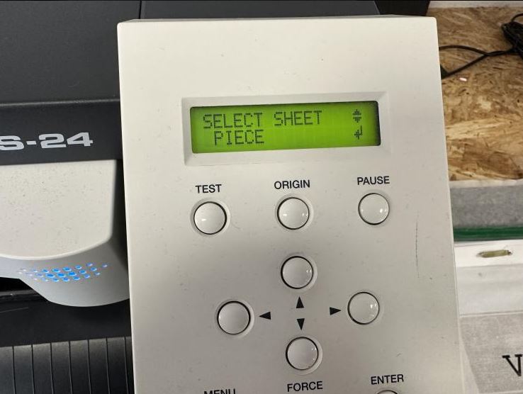
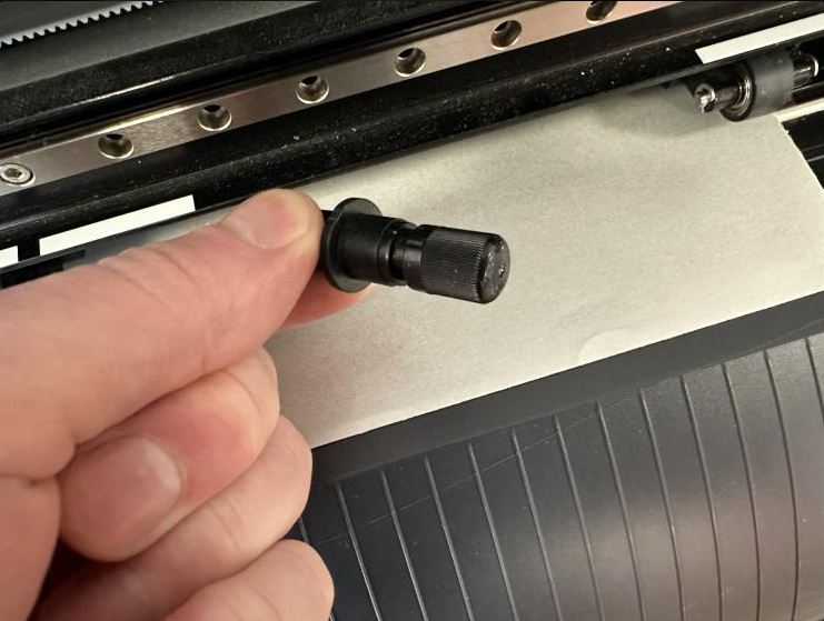
To use the Vinylcutter I start by putting in the Vinyl sheet. The vinyl piece needs to go under the two wheels and the two wheels need to be under the white markings. Once the vinyl is secure I tell the machine that I am working with a Piece, then the machine measures the length and width of the vinyl piece. WARNING! do not tell the machine you are workig with a Roll, the machine will roll out the entire roll to know the length. I then simply open up my .pdf file and hit print and the vinylcutter cuts along the stroke lines. Once in a while the knife of the vinlycutter needs to be adjusted. To adjust the knife, to cut deeper or less, you remove the knife holder and adjust the cut depth by rotating the holder and watch the knife go further out or further in.
Vinylcutter wheels
Vinylcutter "Piece"
Vinylcutter knife
To save on materials I used scraps of vinyl and cut each layer with the vinyl cutter. I did not have scraps in the same colors as the original design so I had to use different colors. Here you can see all layers arranged on a single sheet.
Once I had all layers cut I used transfer tape to combine the layers in a single design. Starting with the gray cloud layer I overlayed the black layer ontop of the cloud. The next layer was the red layer, I carefully placed the red layer ontop of the black and gray layers using transfer tape. Finally the blue layer, small dots inside the letters, was a bit tricky. I ended up doing each letter individually using transfer tape to get the blue dots in place.
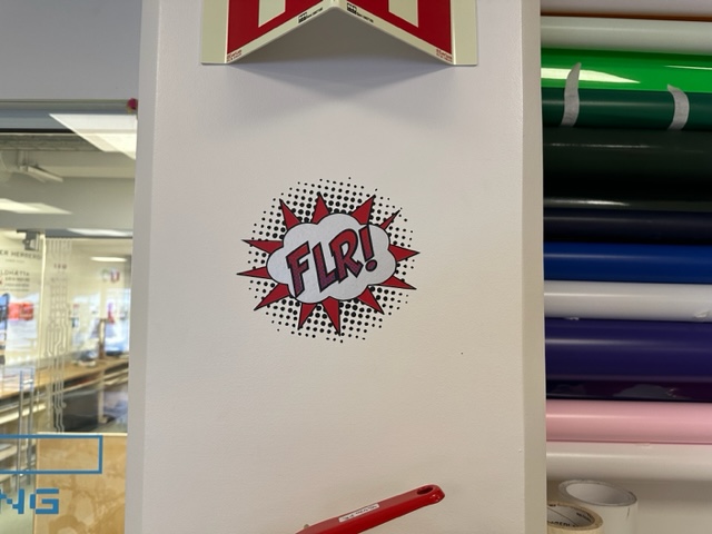
I then used transfer adhesive to get the design on a wall.
One thing to mention is that if I were to use this style again I would use the inverse for the dots, meaning instead of having each dot as a sticker I would have the background as a sticker and the dots as the cut out because I had to spend way too much time on weeding and making sure the dots transferred correctly.
Laser cutter
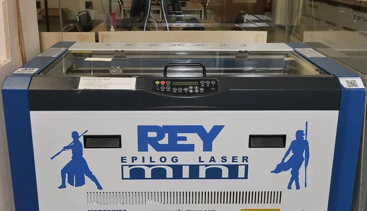
Fab Lab Reykjavik has three laser cutters, 2x Epilog mini 40 and 1x Epilog Fusion M2 40. For my assignment I used the Epilog mini 40
- Model: Epilog mini 40
- Engraving Area: 610 mm x 305 mm (24 in. x 12 in.)
- Max. material thickness: 203 mm (8 in.), engraving area: 597 mm x 298 mm (23.5 in. x 11.75 in.)
- Laser Wattage: 40 watts
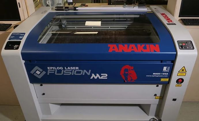
- Model: Epilog Fusion M2 40
- Engraving Area: 1016 mm x 711 mm (40 in. x 28 in.)
- Max. material thickness: 337 mm (13.25 in.)
- Laser Wattage: 40 watts
Design, lasercut, and document a parametric construction kit, accounting for the lasercutter kerf, which can be assembled in multiple ways, and for extra credit include elements that aren't flat
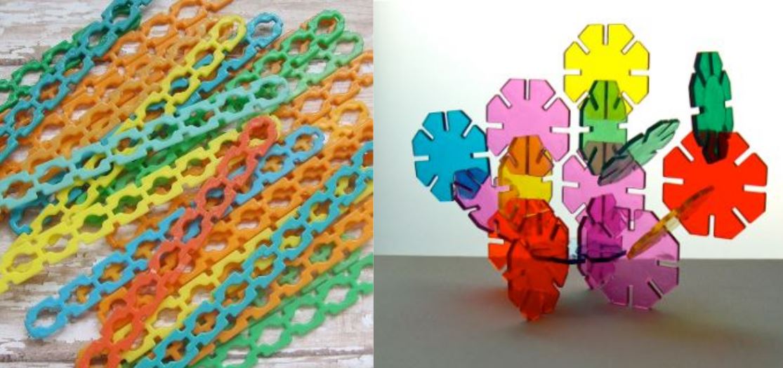
For this week I wanted to make a construction kit that could be used to construct a variety of different shapes. For inspiration I looked at interlocking popsicle sticks and Octons. I wanted my kit to have a variety of different shapes and sizes and be able to construct (almost) anything.
I jumped into Fusion and started working on different shapes, making sure to use parameters wherever I could.
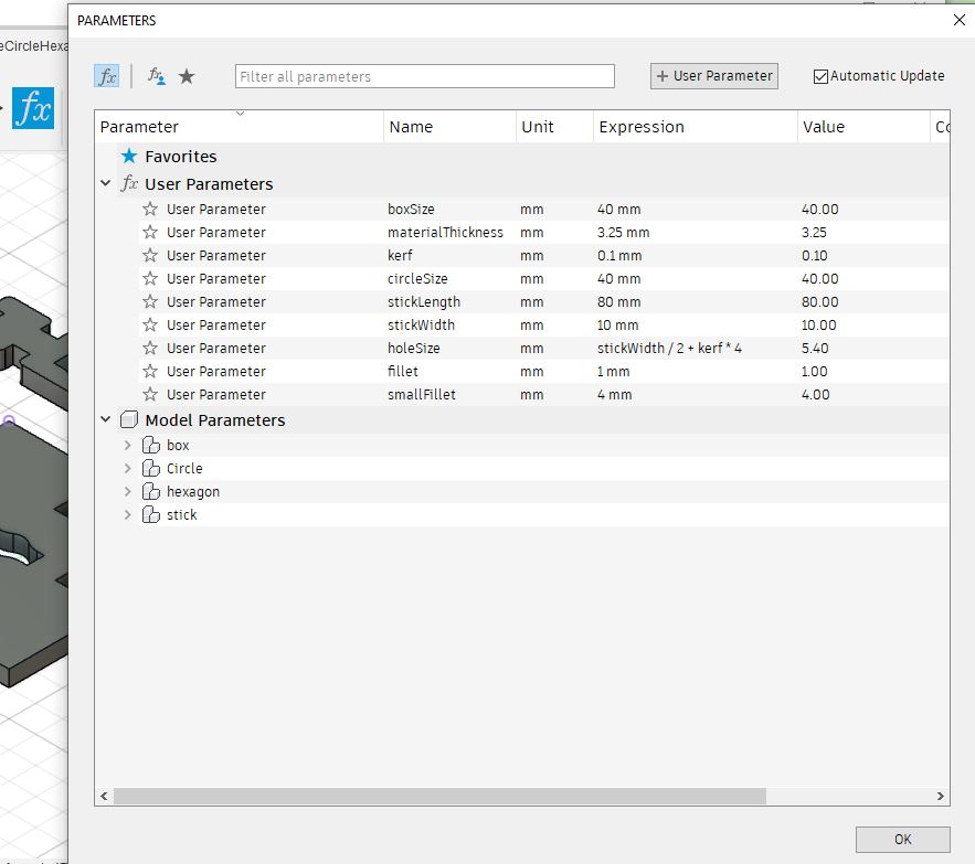
I started by making the parameters. In the Design tab, hit the fx button (Change Parameters) which opens the Parameters window. In the Parameters window I made some basic sizes such as the stick length and box size. Then when I created the sketch for each shape I used the parameters instead of hard coding the dimensions.
I started working on the stick shape, it took a while to make the first version which did not work as expected, the hole was not big enough.
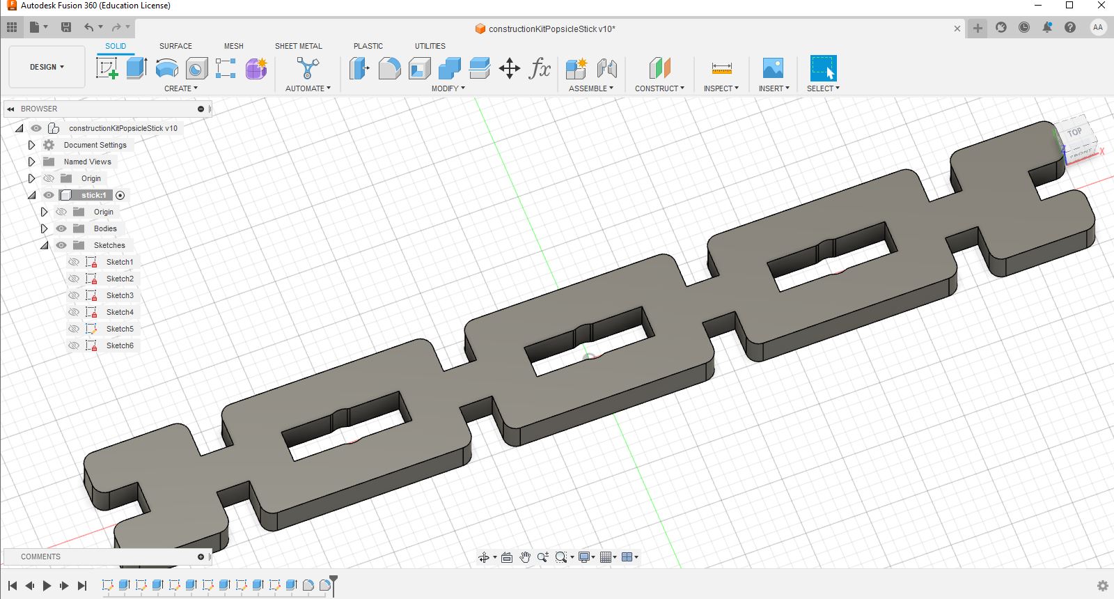
So, I made another version with a bigger circular hole in the stick.
I modeled the stick using parameters so I could easily change the size of the stick, the notch sizes also used parameters and accounted for different kerf offsets, ex. notchSize+kerf. To get a file for the laser cutter I saved the top face as a DXF file and brought it into Inkscape. When I imported the DXF into Inkscape the dimensions were wrong, the stick width was only 8mm when I designed the width in Fusion to be 80mm. That was an easy fix inside Inkscape. I also needed to delete some of the sketch lines I did not need to laser cut.
I laser cut the file and found that the kerf was off so I made a few different versions, 0.1mm, 0.2mm and 0.3mm kerf and found that for the kerf parameter 0.3 mm was the best.
Here you can see a few pieces of the stick shape snapped together.
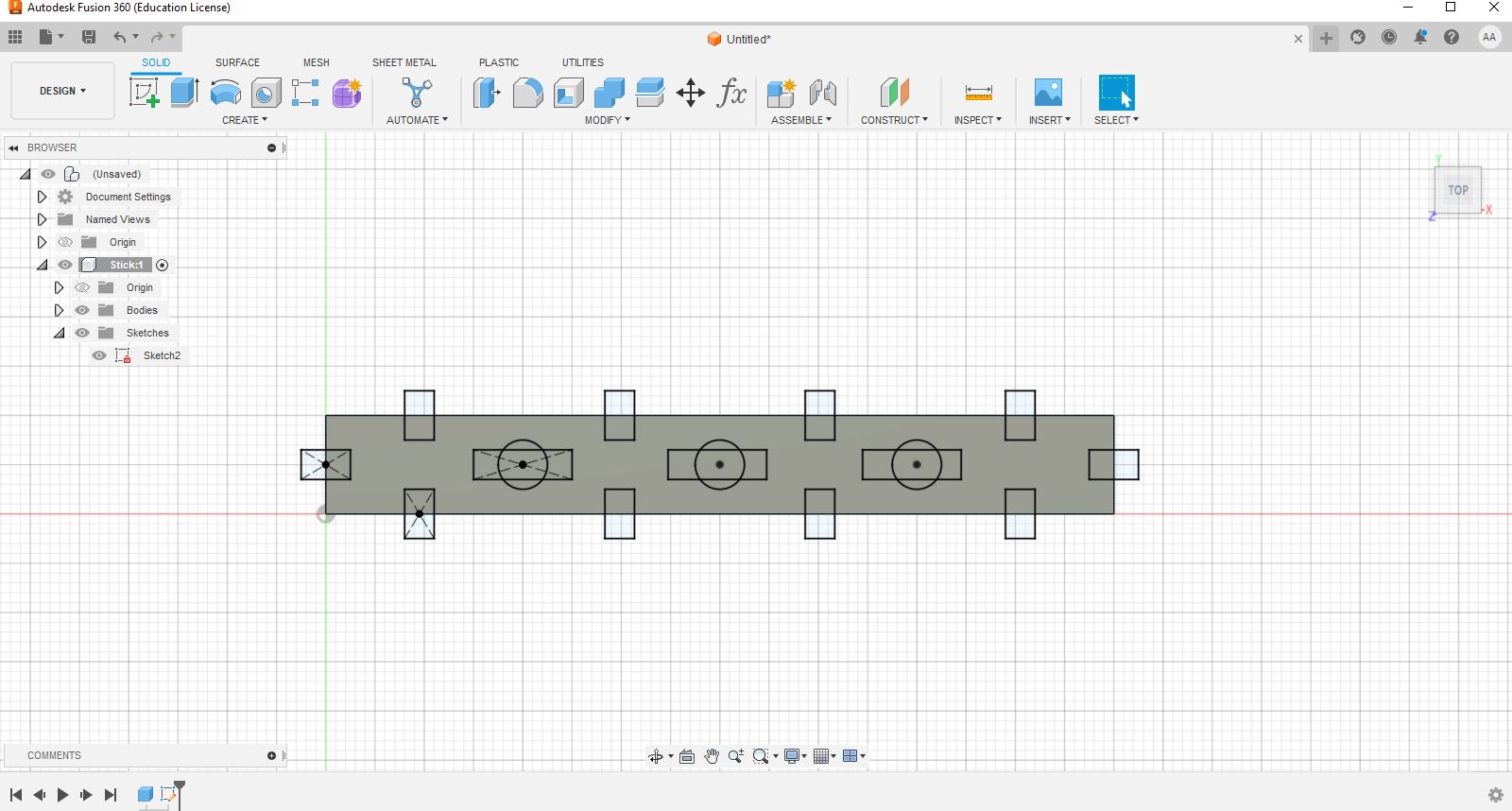
I wanted to experiment more with Fusion so I decided to make more shapes that could snap together with each other and the stick shape. As before I made all shapes using parameters and included kerf offsets.
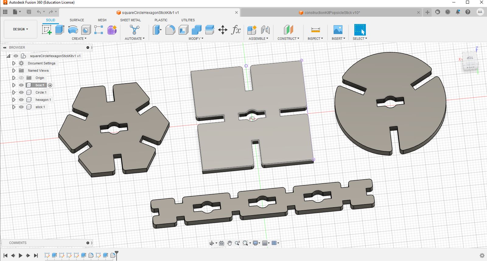
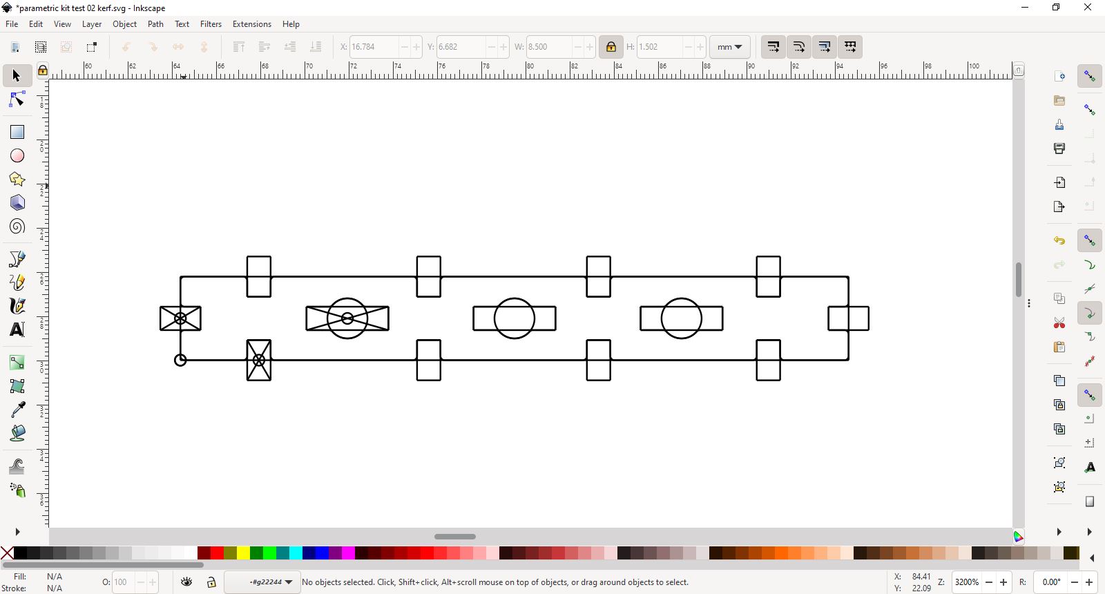
I exported the shapes from Fusion, I meant to export each shape individually but when I imported a DXF file into Inkscape, which I thought was only the square shape, all shapes in the Fusion file were imported. I also noticed that the shapes multiplied with each move within Fusion.
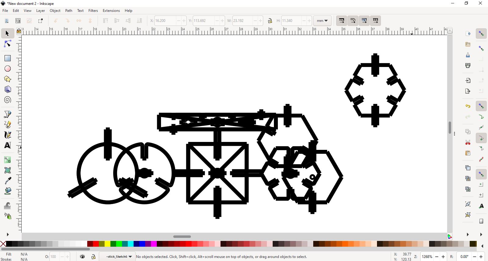
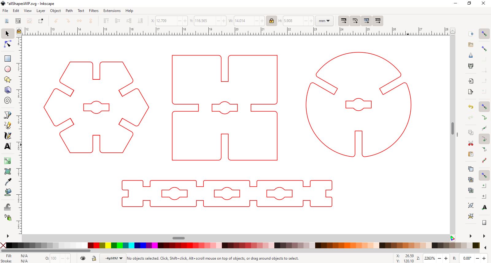
As before the scale of the shapes were 1/10 of the Fusion file. I cleaned up the Inkscape file and prepared for laser cutting.
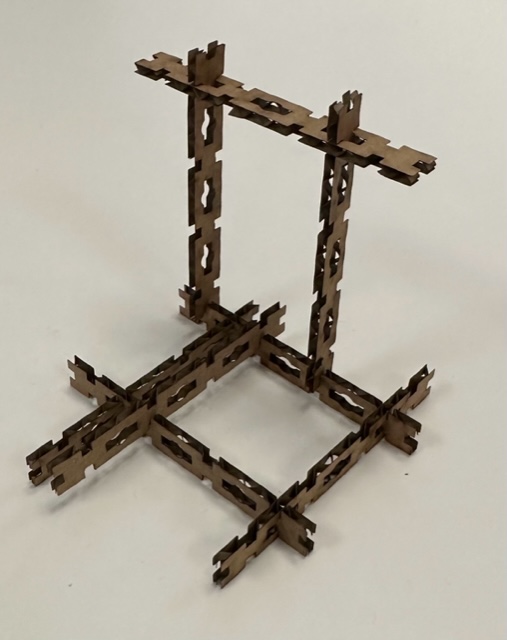
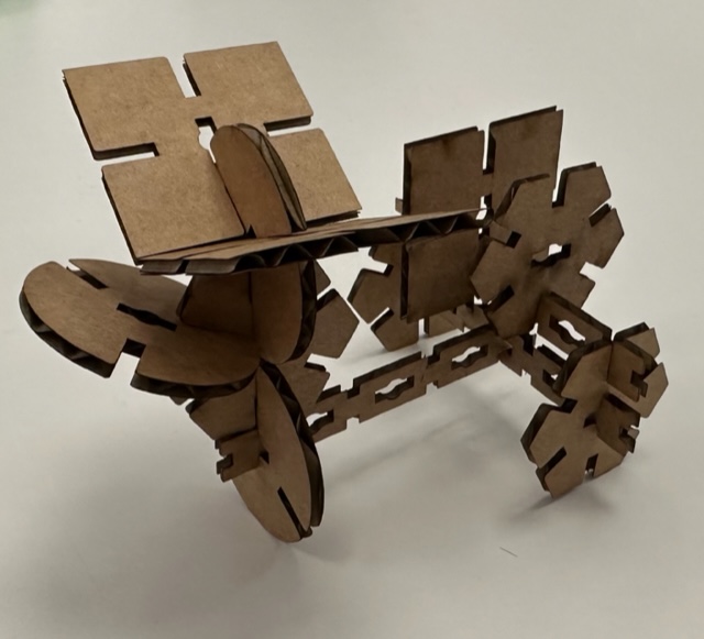
I cut a few pieces of each shape and snapped everything together. The cardboard I was using was a bit flimsy but I was able to snap all the pieces together. I was able to make a few different shapes with the kit.
I wasn´t happy with how flimsy the cardboard was and I found it odd that 0.3mm kerf was the best so I decided to try again using woodboard. I had 3mm woodboard and the fit was way too tight, so I went back into Fusion and tried exporting with the kerf at 0.1mm. This time I managed to export just one shape at a time and the shape came in the right scale and no cleanup in Inkscape. I did this by making a new sketch on top of a face and then right clicking the new sketch in the Fusion Browser dropdown and saving as DXF. 0.1mm kerf was still too tight so I tried again with 0.05mmkerf. Still no go, so I thought I should double check my material thickness and found that the woodboard was actually 3.25mm thick. So, back to Fusion, this time I changed the thickness parameter and exported two shapes at 0.05mm and 0.1mm kerf.
This time the sides slid together to my liking, I preferred the 0.1mm kerf because it was not as stiff as the 0.05mm kerf. However the stick shape did not want to turn inside the holes of the shapes so I went back into Fusion to fix the hole size.
This time everything fit perfectly together. I see now the power of parameters. It would have been a real pain doing the changes I did manually, and now I can make these shapes in any size and material thickness. I learned a lot this week. I learned how to work with parameters in Fusion and never trust when someone tells you the material thickness, always measure it yourself.
Group assignment
Characterize your lasercutter's focus, power, speed, rate, kerf, joint clearance and types
For this project I worked with Hafey , a fellow student working out of Fab Lab Reykjavik. My part in the assignment was creating a file to measure the raster and vector of our laser cutter. The file is a grid with different Speed and Power settings to see the difference in each setting. I sat and watched as the laser cutter rastered the grid. I also used the same file again but this time I checked the difference in the vector. The first time the settings were too low to actually cut through the wood but still showed difference in how deep the laser went and the deeper it went the darker the lines. The second time I really toned down the speed setting and saw at which point the laser stopped cutting through the wood. See full documentation for the group assignment here.
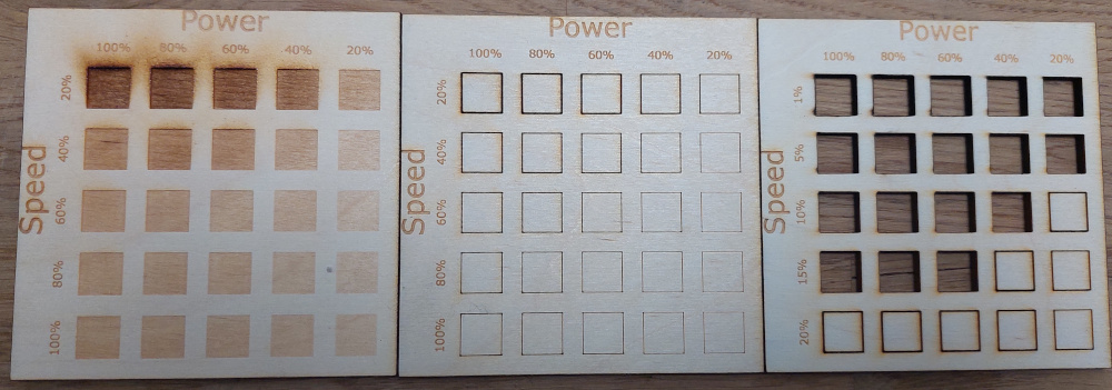
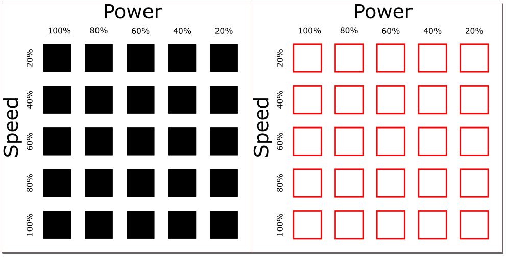
To raster each box in the grid open the Inkscape file and save the file with one square visible at a time and raster/vector each individual square with each setting.