Individual Assignment
Measure something: add a sensor to a microcontroller board that you have designed and read it.
Group Assignment
Probe an input device(s)'s analog and digital signals.
Document your work on the group work page and reflect on your individual page what you learned.
Learning outcomes
- Demonstrate workflows used in sensing something with input device(s) and MCU board.
Measure something: add a sensor to a microcontroller board that you have designed and read it.
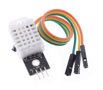
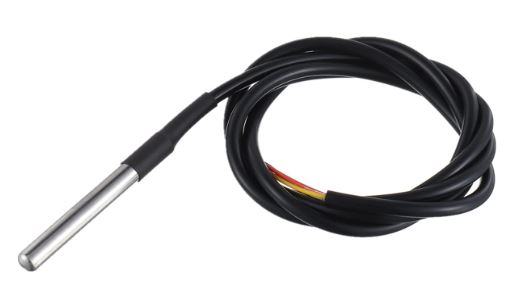
This week I wanted to test at least two different input sensors alonside an output device. The first input sensor I wanted to test was DHT22 Temperature and Humidity sensor. The second sensor, DS18B20 , is a waterproof temperature sensor.
DHT22 Temperature & Humidity sensor
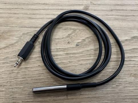
DS18B20 Waterproof Temperature sensor
I started by wiring the dht22 sensor to a Xiao esp32-c3 board. It was pretty straight forward getting the temperature and humidity readings from the sensor and print on the serial monitor. However, I wanted to display the readings on a SSD1306, 0.96" OLED display.
SSD1306 0.96" OLED display
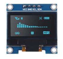
I´ve used this type of display before on an Arduino Uno but I was unable to use the same library on the Xiao esp32-c3 board. After some research online I found the U8g2 library which worked perfectly.
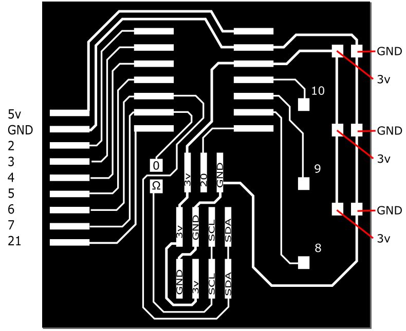
After I got everything working I started on a board to connect everything together.
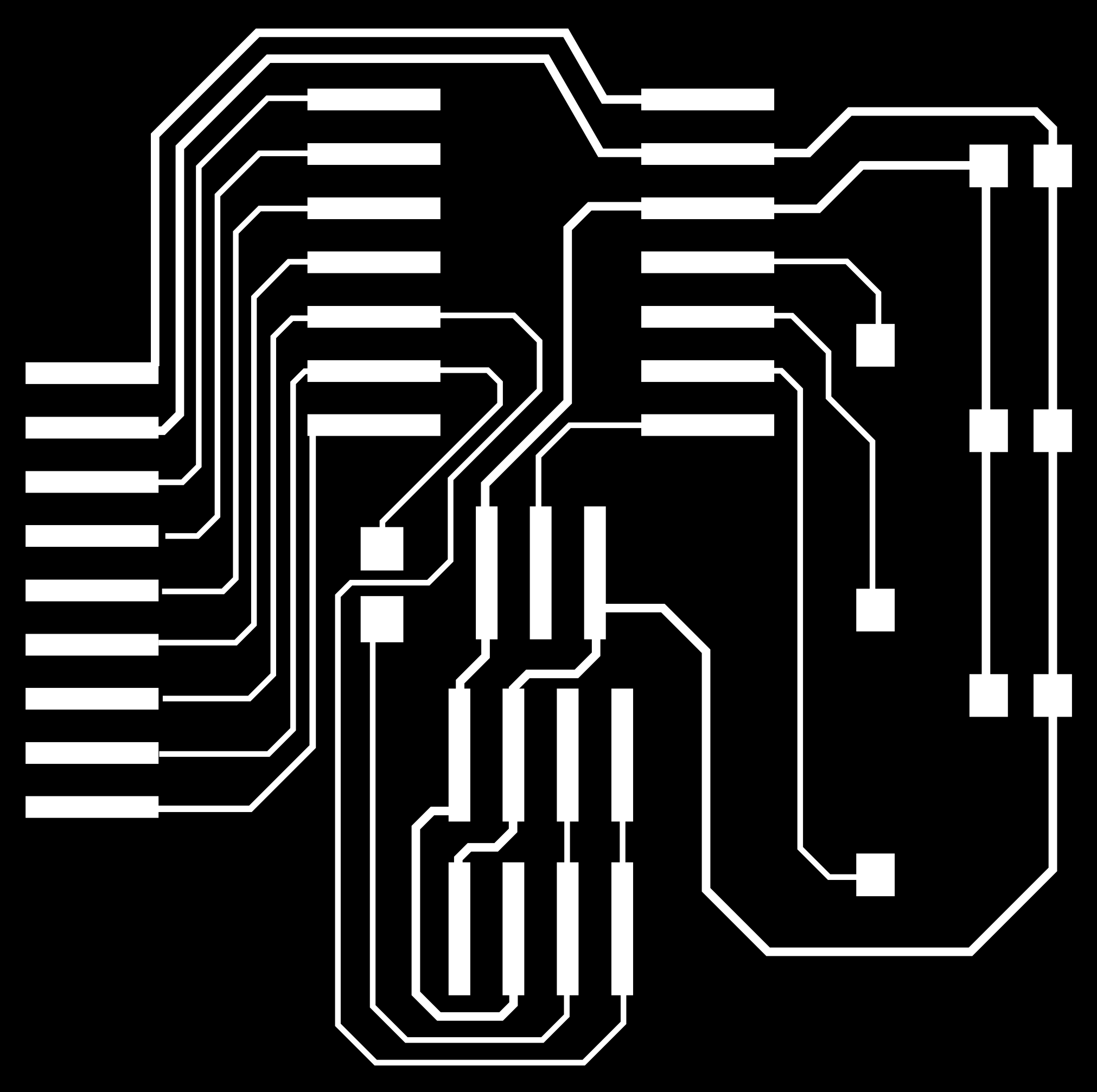
Using Inkscape I created a mounting board, that can mount a Xiao board, with three headphone jack type connectors, two mounts for the OLED display and extra connectors to use all the pins on the Xiao. The reason I put two connectors for the OLED display is because I have two variants of the OLED, one variant has the following pins in order GND, VCC, SCL, SDA while the other has in order VCC, GND, SCL, SDA.
Input devices board
Input board board Inkscape
Milling the board went well so I started soldering the connectors along with the one 0Ω jumper resistor.
Soldering Input board
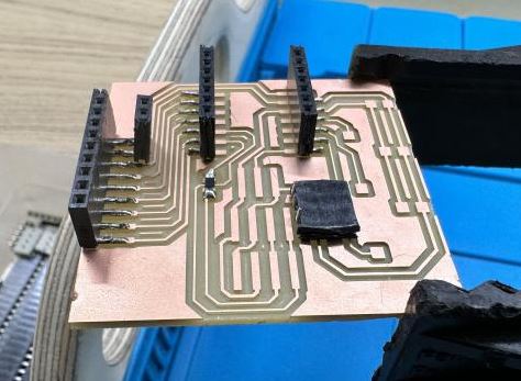
Input board soldered
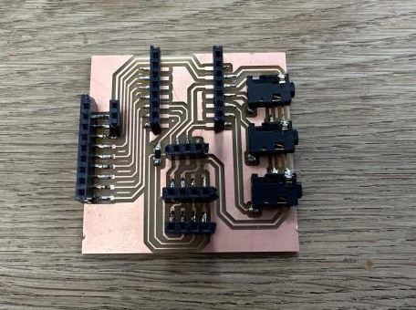
To get the DS18B20 sensor connected to the board I had to solder the wires to a headphone jack.
Soldering wires to headphone jack
DS18B20 with a headphone jack
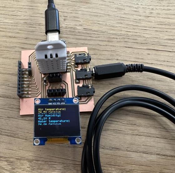
I plugged everything to the board and loaded the code I had tested before. Everything worked perfectly. The DHT22 sensor gives temperature and humidity readings and the DS18B20 sensors gives temperature readings. Both OLED connections work.
SSD1306, VCC, GND, SCL, SDA
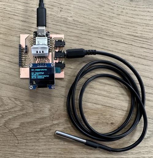
SSD1306, GND, VCC, SCL, SDA
Input Device Video
Joystick for Final Project
For my final project I plan on making an arcade machine with a joystick and buttons. The joystick has simple mechanics, it´s basically four switches that get avtivated when the joystick is moved.
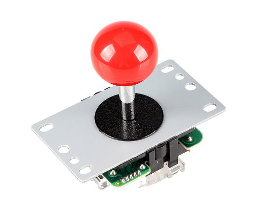
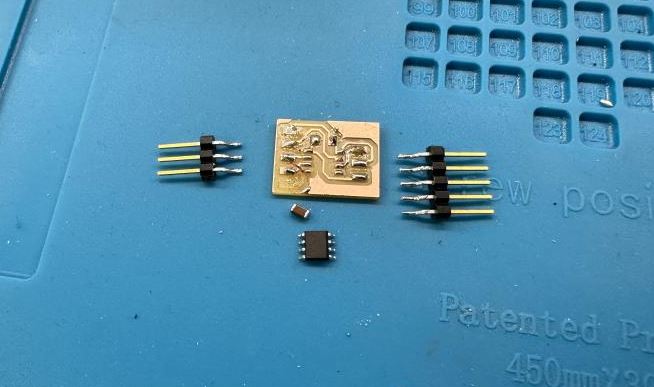
I have still not decided how exactly I will implement the joystick in my final project but for now I wanted to test the joystick and make a simple board with an Attiny412 microcontroller to read the joystick values and print to Serial monitor.
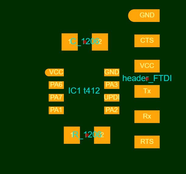
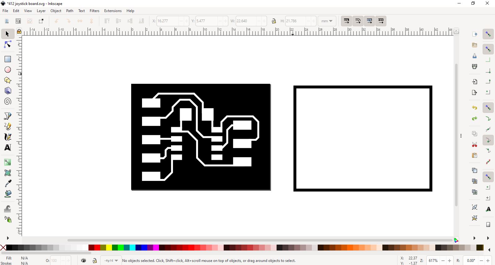
I started making the board in SVGPCB but after I got all the footprints I needed I grabbed them and brought into Inkscape.
412 Joystick footprints in SVGPCB
412 joystick board in Inkscape v1
I milled this version, it took a few tries because the milling machine was acting up but after I restarted the mods software we use and turned off the machine and on again it milled perfectly.
Milling the 412 joystick board
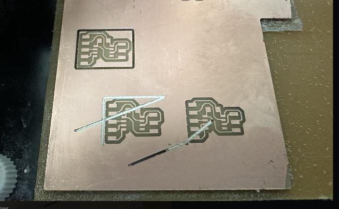
412 joystick board v1
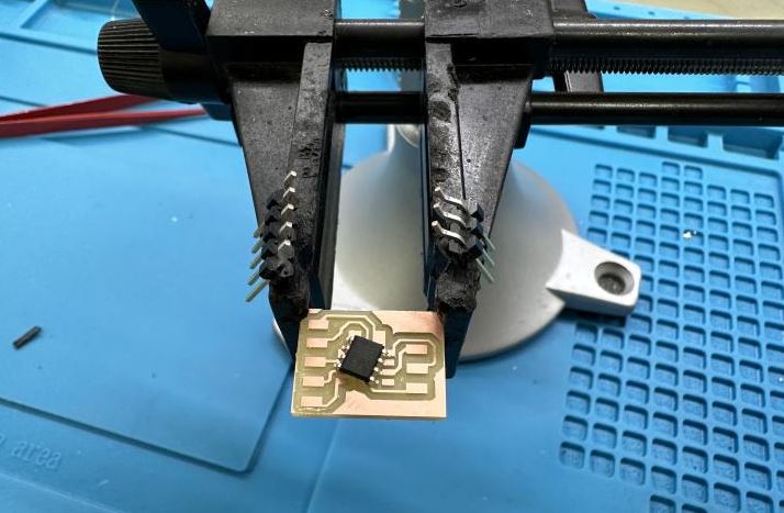
I soldered the components and using the serial UPDI 3-pin board I made in Electronics Production Week I connected the 412 joystick board and a USB-FTDI cable and programmed the 412. After programming I realized that to get Serial communication I would need both RX and TX pins. The only pin not routed on my board was the RX pin.
So I edited the board design in Inkscape, rerouting a few connections and adding pins so I could use the USB-FTDI cable to receive Serial communication.
412 joystick board v2

412 v1 scrapped for components
Download 412JoystickBoardv2 Inkscape .svg file
I milled the v2 of the 412 joystick board and using the scrapped components from v1 I soldered the v2 board.
Again, using the serial UPDI 3-pin board with a USB-FTDI cable I programmed the board, connected the joystick and got Serial communication.
412 joystick board Video
Download 412Joystick .ino code
Group Assignment
Probe an input device(s)'s analog and digital signals.
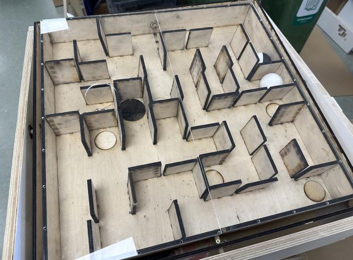
For our group project me and Hafey probed the input signals of a PlayStation remote, controlling stepper motors.
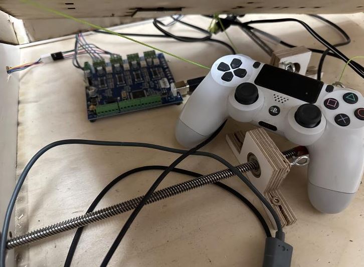
The PlayStation remote is connected to a Stepper Motor Control Board controlling two Stepper motors controlling a maze game.
The PlayStation remote is hardwired and the probes are connected to the Stepper Motor Control Board.
Maze game
Maze game internals, Stepper Motor Control Board and PlayStation remote
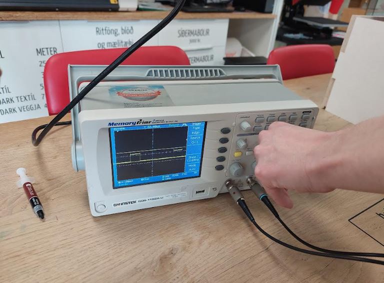
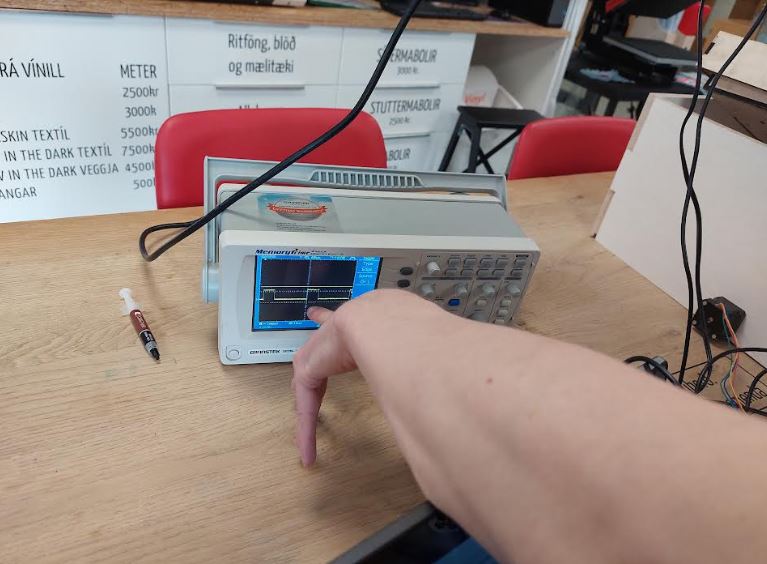
Using an oscilloscope we probed and measured the signals from the PlayStation remote controlling the steppers.
Oscilloscope img 1
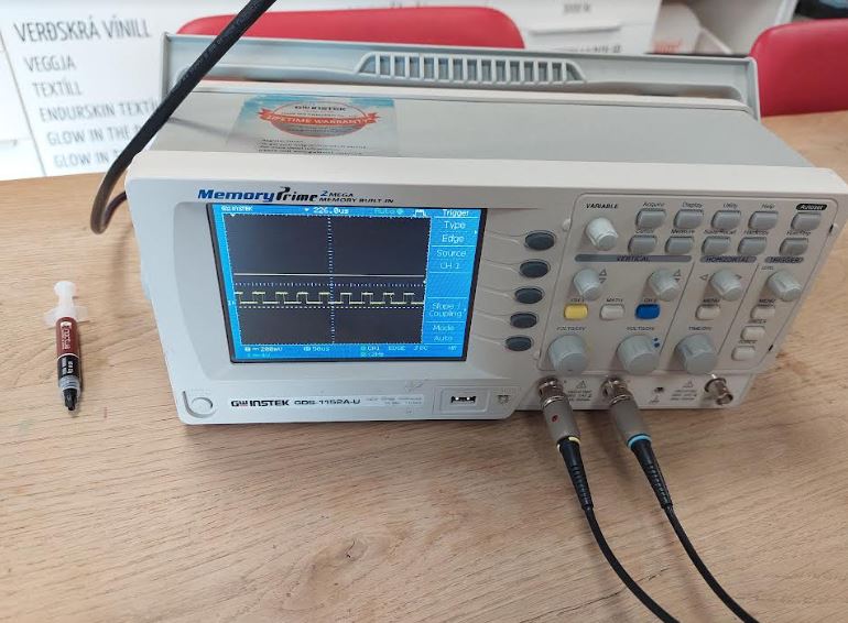
Oscilloscope img 2
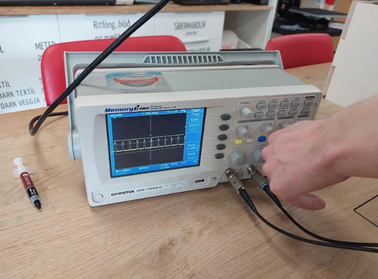
Oscilloscope img 3
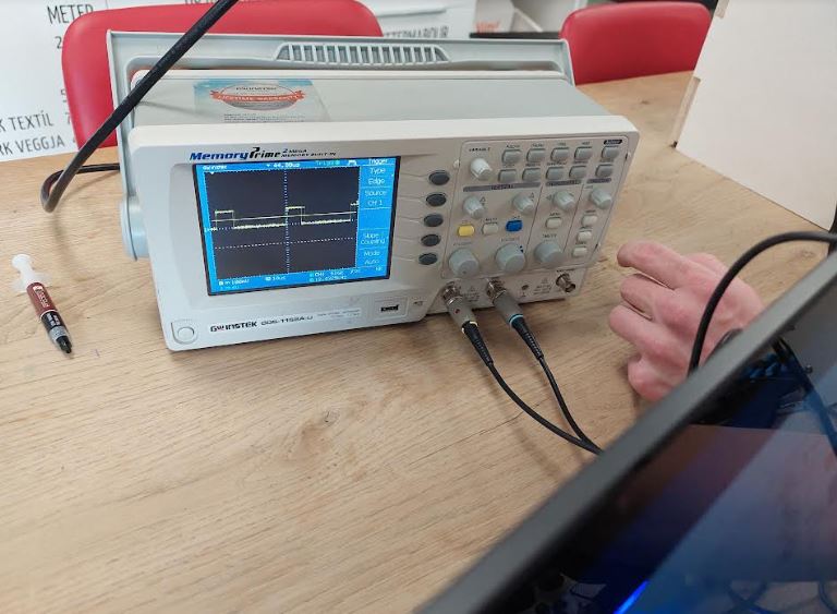
Oscilloscope img 4
Oscilloscope img 5
The oscilloscope shows how electrical signals change over time by graphing them as waves on a screen. It displays these signals as waveforms on a screen, allowing you to visualize the amplitude (strength) and the frequency (rate of change) of the signal over time. This helps in analyzing and troubleshooting electronic circuits and systems.
Square waves are typically generated by electronic devices called oscillators. These devices produce a waveform that rapidly switches between two voltage levels: a high level (often represented by a positive voltage) and a low level (often represented by zero or a negative voltage). The transition from high to low and vice versa is almost instantaneous, resulting in the square shape. Square waves are commonly used in digital systems and electronics because they have well-defined transitions between high and low levels, making them suitable for representing binary data (0s and 1s) in digital circuits. They are also useful for testing and evaluating electronic components and systems, as their distinct shape makes it easier to detect and measure certain characteristics of the signal, such as rise time and fall time.