Individual Assignment
Make (design+mill+assemble) something big.
extra credit: Don't use fasteners or glue.
extra credit: Include curved surfaces.
Group Assignment
Complete your lab's safety training.
Test runout, alignment, fixturing, speeds, feeds, materials and toolpaths for your machine.
Document your work on the group work page and reflect what you learned on your individual page
Learning outcomes
- Demonstrate 2D design development for CNC production/li>
- Describe workflows for CNC production
Make (design+mill+assemble) something big.
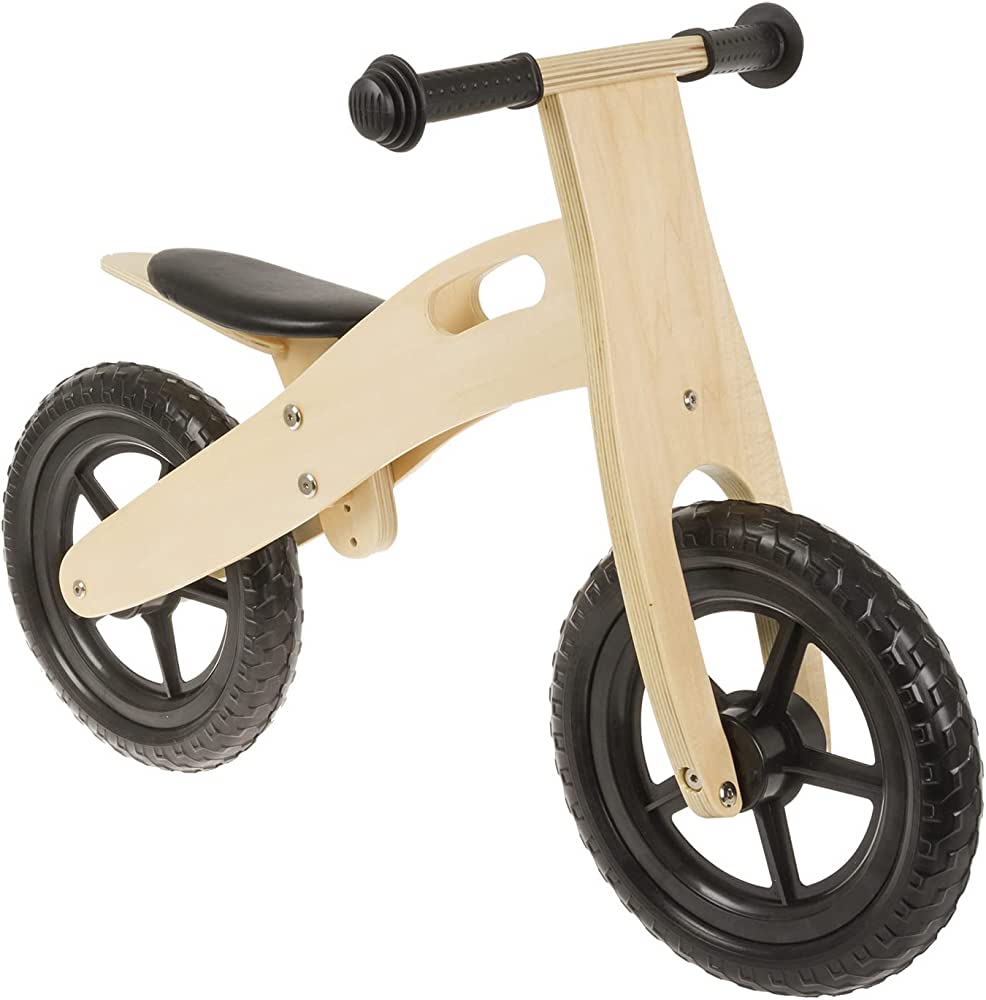
For this assignment I first thought of making a balance bike for a young child or even making an big version of a balance bike for an adult.
Inspiration
Inkscape Design
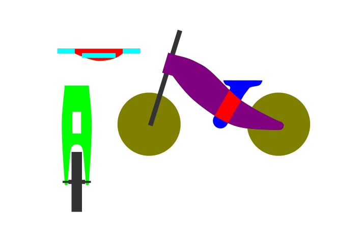
I started making a design in Inkscape and I was almost finished when I attended the Global Open time with Adrian and Rico. In the Global Open Time they really stressed the importance of understanding the machine and suggested focusing on different types of joints. Since my bike design did not have any joints and relied on screw fasteners so I decided to go a different route and make something that could possibly benefit my final project. In my final project I plan on making a mini arcade machine and possibly use the Shopbot milling machine to make the arcade box.
I haven't decided if I will laser cut the arcade box or use the cnc mill so instead of milling the arcade box I wanted to make some sort of game and incorporate different joints. I looked online for different types of simple games and first I thought of making a Novuss board or a Sjoelbak game.
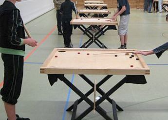
Novuss
Sjoelbak
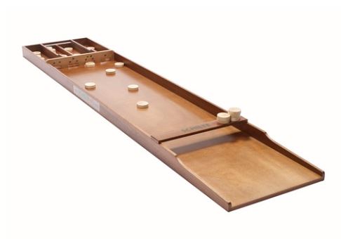
I decided against making a Novuss board since it requires a cue stick to play, and I decided against the Sjoelbak since the official size of the board is about 2 meters in length. But I liked the disc aspect of both games so after some googling I found a Carrom board. I have seen videos of people playing Carrom but I have never tried it myself.
Carrom board
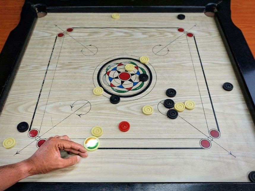
I started making a design in Inkscape and had everything designed at home. I designed my board for 22mm plywood but when I got to the lab the thickest plywood I found was 17.5mm. So, I had to recreate my deisgn for 17.5mm material. I brought my design into VCarve and made all the toolpaths. I made a small mistake in my design where the joints for the border was placed on the wrong side and would overlap the board.
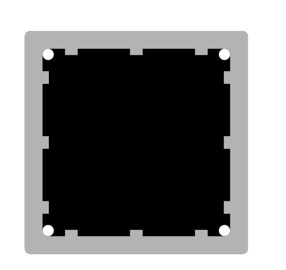
Carrom board v1 Joints on the wrong side./h4>
Border frame milled
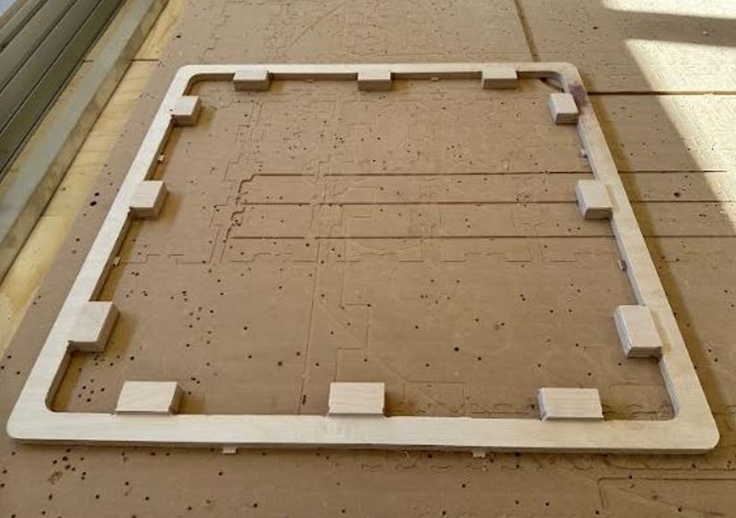
I didn´t notice the mistake until after I stated milling so I thought of trying to get away with it saying I had created a new game by accident but wanted to create a real Carrom board so I re=designed the border.
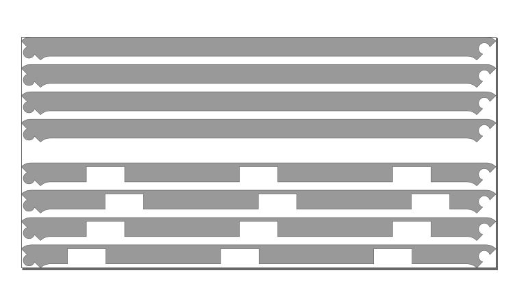
To save on material I decide to split the border frame in four pieces and made a circular joint to connect the pieces.
Border re-design

Border split in four with joints
I was able to save my design and fit the new border edges on my board.
Carrom board final design in Inkscape
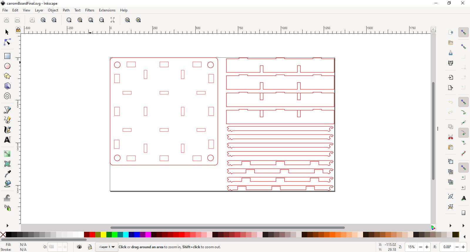
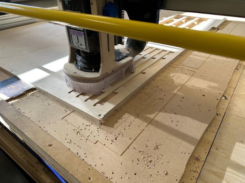
Milling the re-design borders
Carrom board in VCarve
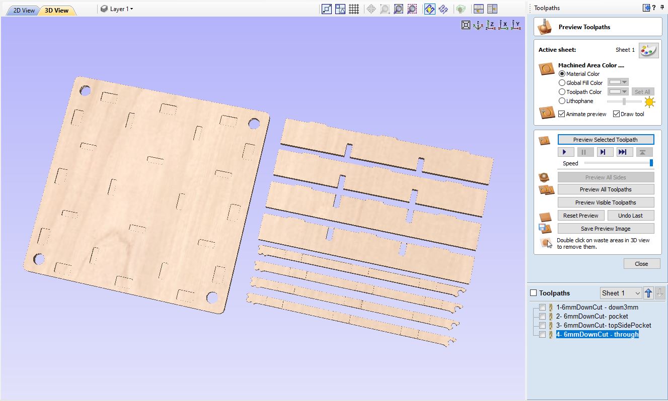
Notice, this file does not have any tabs in the toolpaths, also, the .crv file was made in a trial version of VCarve and needs to be imported into a full version to export toolpaths and access all features.
Milling strategy
For assembly and milling I wanted to create push-in or snap joints to connect everything together. The legs that support the bottom have half-lap joints where I milled each part in half using the material thickness for reference. To assembled the leg pieces I slide them together. The leg pieces also have tabs to connect to grooves the board piece. The board piece has grooves on on top and bottom. The top grooves connect to the side pieces. The bottom grooves connect to the legs.
For milling I start by milling 3mm into the material with a 6mm downcut milling bit. I then cut through the entire material with a 6mm upcut milling bit.
In VCarve I input the setting for each milling bit. To figure out the correct spindle and surface speed, feed rate and other settings for the milling bit and type of material I used the Fablab Speed and Feeds Calculator.
Carrom board pre-assemble, top
Before adding the new border design.
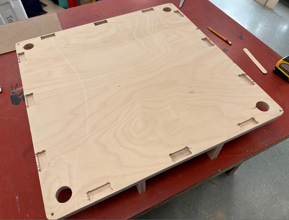
Carrom board pre-assemble, bottom
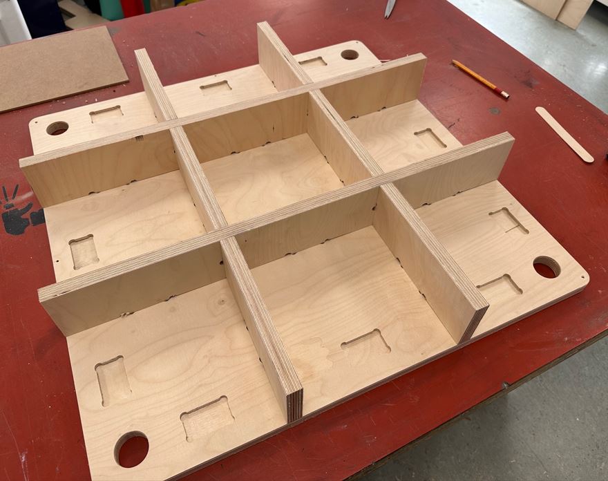
Notice the unused pockets from my border mistake.
Hero shot - Carrom Board assembled
Carrom board
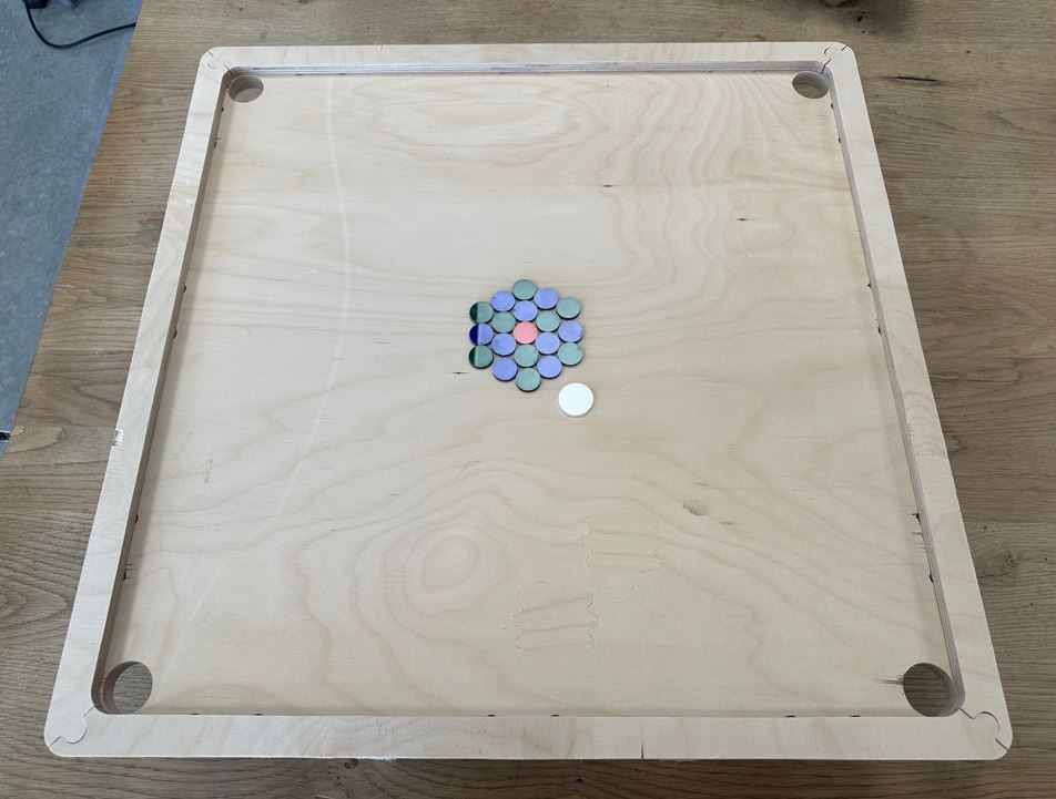
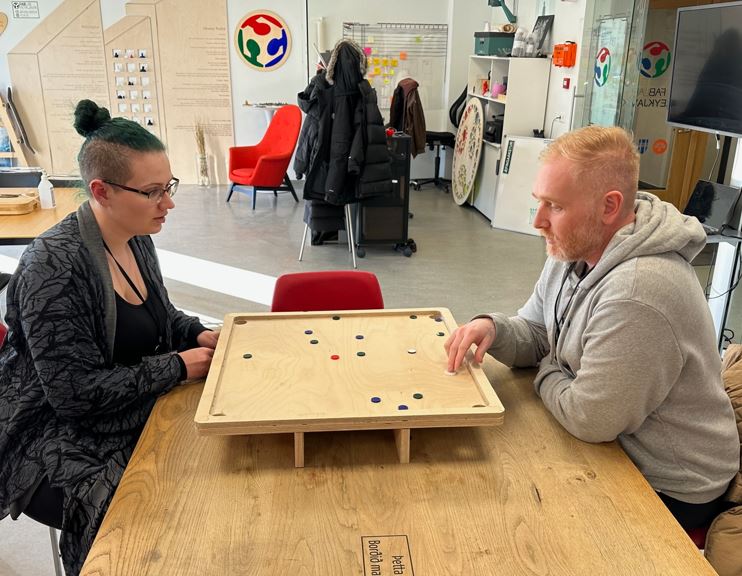
Carrom board mid-game
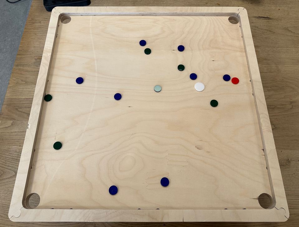
Carrom board playing
Group Assignment
Complete your lab's safety training.
Test runout, alignment, fixturing, speeds, feeds, materials and toolpaths for your machine.
Safety
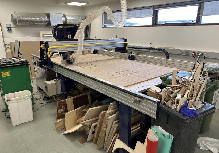
To be able to use the shopbot at Fab Lab Reykjavik you need to take a safety course. The safety course addresses the dos and don´ts of using the shopbot. I have been using the shopbot for about a year now and already took the safety course. The main takeaways from the course is eye protection and long hair should be tied up.
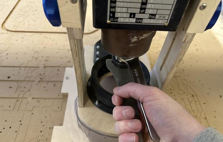
The safety course also goes over in which order the machine should be used, start the milling motor spin before turning on the vacuum. We do this so we hear the motor spinning. If the motor is not spinning when you turn on the project the shopbot would try to mill the project with no rotating milling bit resulting in breaking bits. After the vacuum is turned on and the shopbot starts the project it may be good to use ear protection but still make sure you hear if the shopbot makes weird noises. You also get training on how to change collets and bits.
Changing collet and milling bit
Shopbot power
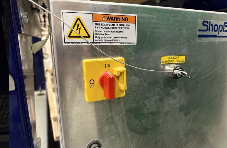
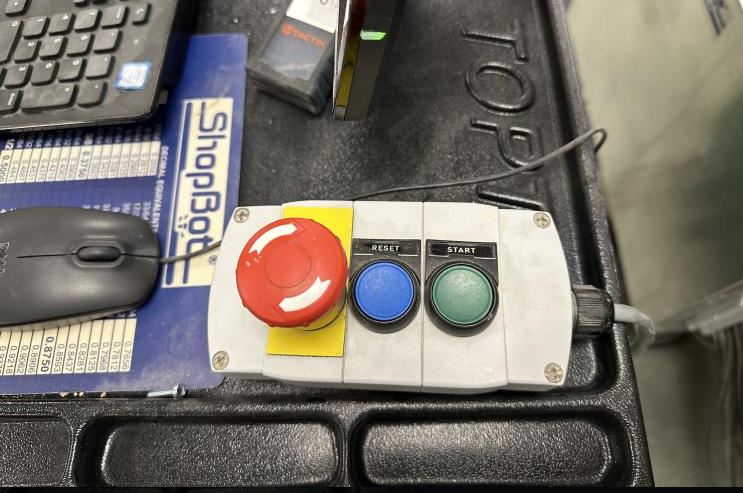
Important takeaway from the safety course is protect you eyes, hair and clothing. Listen and look. And of course know where the emergency stop buttons are placed.
Emergency stop button 1
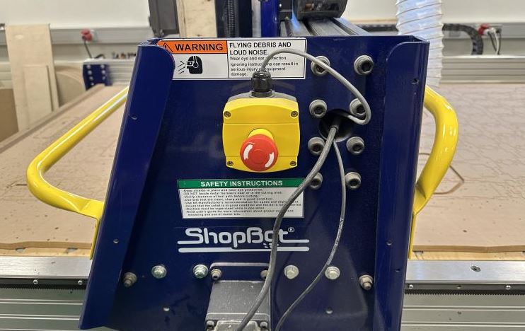
Emergency stop button 2
Test runout, alignment, fixturing, speeds, feeds, materials and toolpaths for your machine.
For our group project me and Hafey made some tests for the Shopbot.
In VCarve I created a 100mm square with a 50mm circle in the middle. I made a pocket toolpath for the circle that went down 5mm. After milling the piece we measured each side to figure out if the Shopbot was accurate enough.
Square test
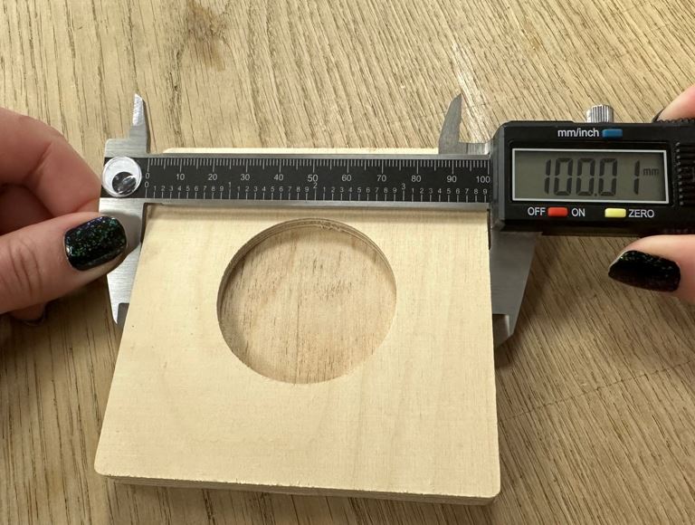
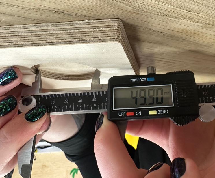
The measurements showed the Shopbot was pretty accurate and within acceptable margins of error.
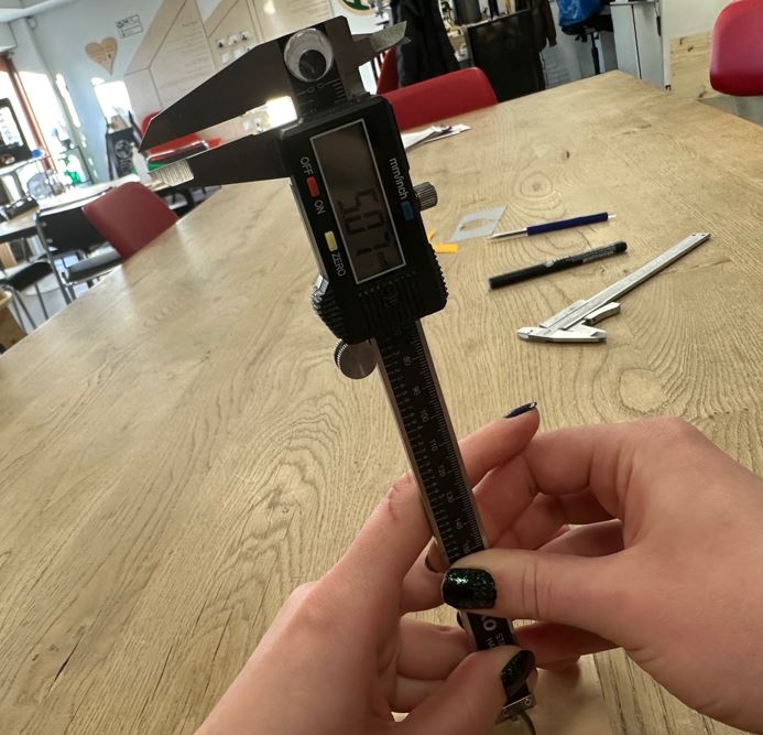
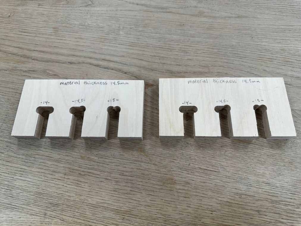
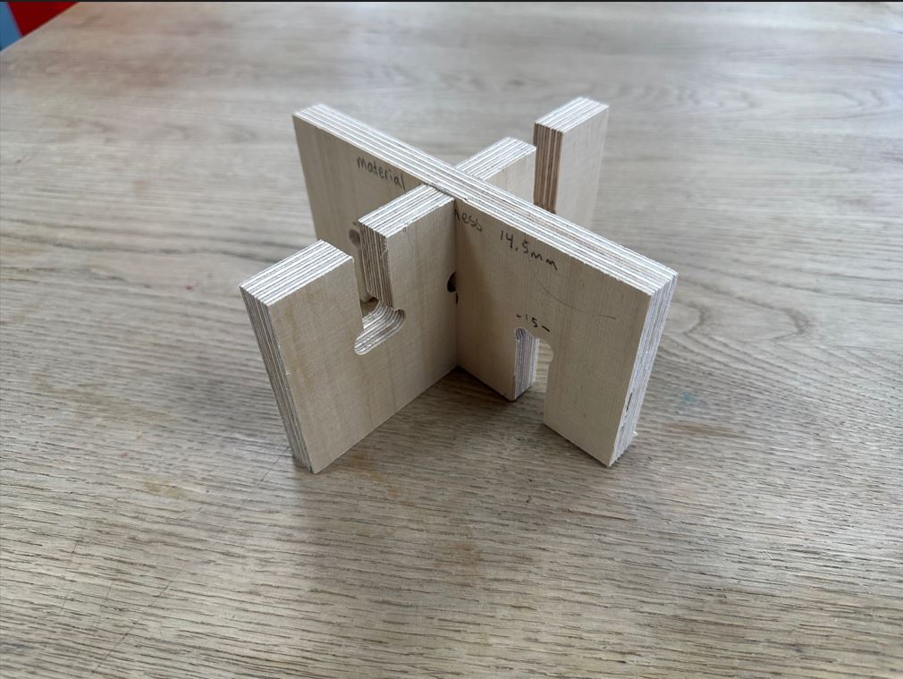
I also created a comb test similar to the test made for the laser cutter. I created a comb test similar to the test we made for the laser cutter to check the kerf. The material I used was 14.5mm thick and I created three slots to see which slot size would make the best connection. One slot was 14mm, the next 14.5mm and the last 15mm. The 14mm slot was too tight and the 15mm slot was too loose. The 14.5mm slot was the perfect size.
Comb test
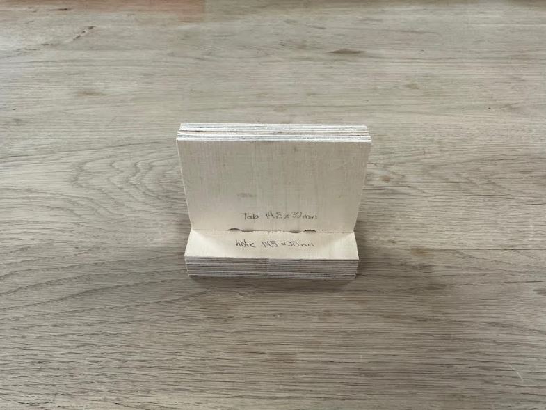
Hafey made a DúbbíDúb test to see which tab size and hole would make a good press fit. Using the same size for the tab and hole made a perfect fit.
To calculate the chip load I used the this function: feed rate (mm/min) / (RPM x number of flutes)
Using a 6mm endmill with two flutes, 14000 RPM and feed rate at 5000 mm/min the chip load calculates to:
5000 / (2 x 14000) = 0.178