Output Devices
Project description
Group Assignment
Measure the power consuumption of an output device.
Individual Assignment
Add an output device to a microcontroller board you´ve designed, and program it to something.
The LED strip was connected to 5v, GND and D5 on the XIAO. I measured the Volts and Amps for each color and used the formula P=VxI to find the power consumption. Example 4.9v x 0.06A = 0.29W. What I learned for this process is that not all LED lights/colors used the same power consumption.
This week I had to use the multimeter to measure the voltage of the LED strips and calculate the energy consumption. I used the programing that was on the PCB board from week 8.

I used a multimeter to measure the power consumption of my led strips.
Using the formula P = V x I
Example: P = 4.9v, V = 0.06A, We can find I (Watts) with I = P x V
I = 4.9v x 0.06A = 0.294W
| 4.9v | ||
|---|---|---|
| Fire | 0.06A | 0.294W |
| Red | 0.11A | 0.539W |
| Yellow | 0.19A | 0.931W |
| Greenish Yellow | 0.24A | 1.176W |
| Green | 0.11A | 0.539W |
| Blue | 0.11A | 0.539W |
| Purple | 0.09A | 0.441W |
| White | 0.28A | 0.372W |
From my measurements I can tell that different colors have different power consumtion. I used the program that was on the chip from week 8. It also gave me knowledge to use in later weeks.
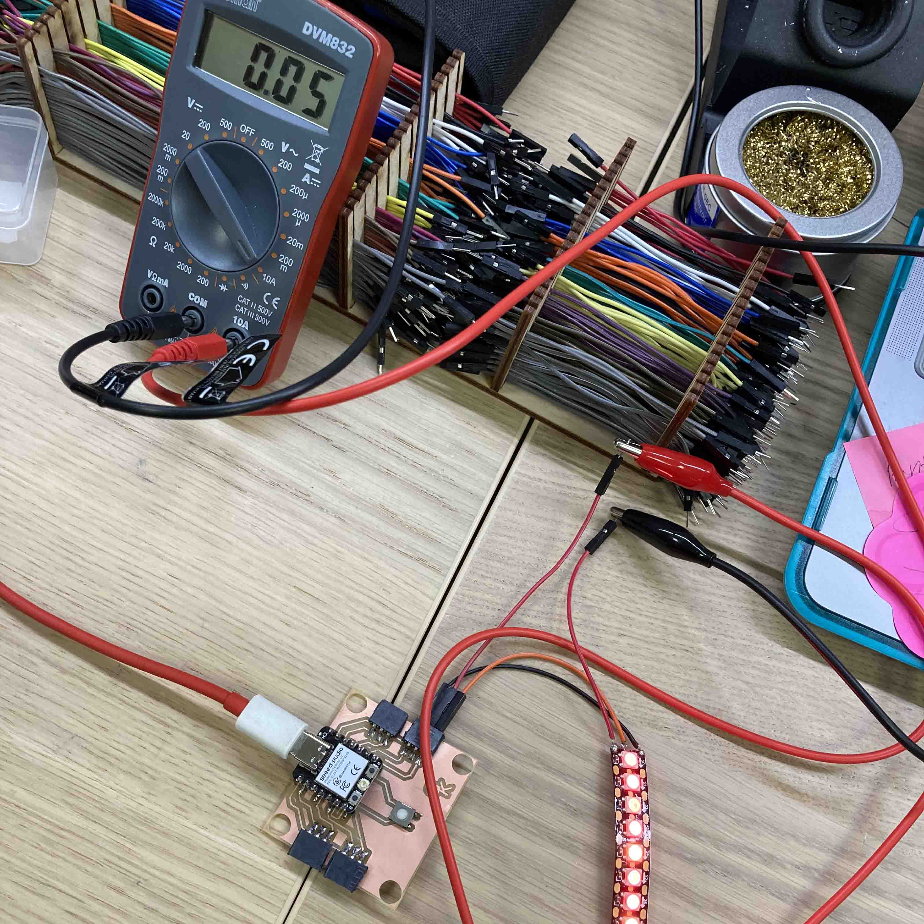
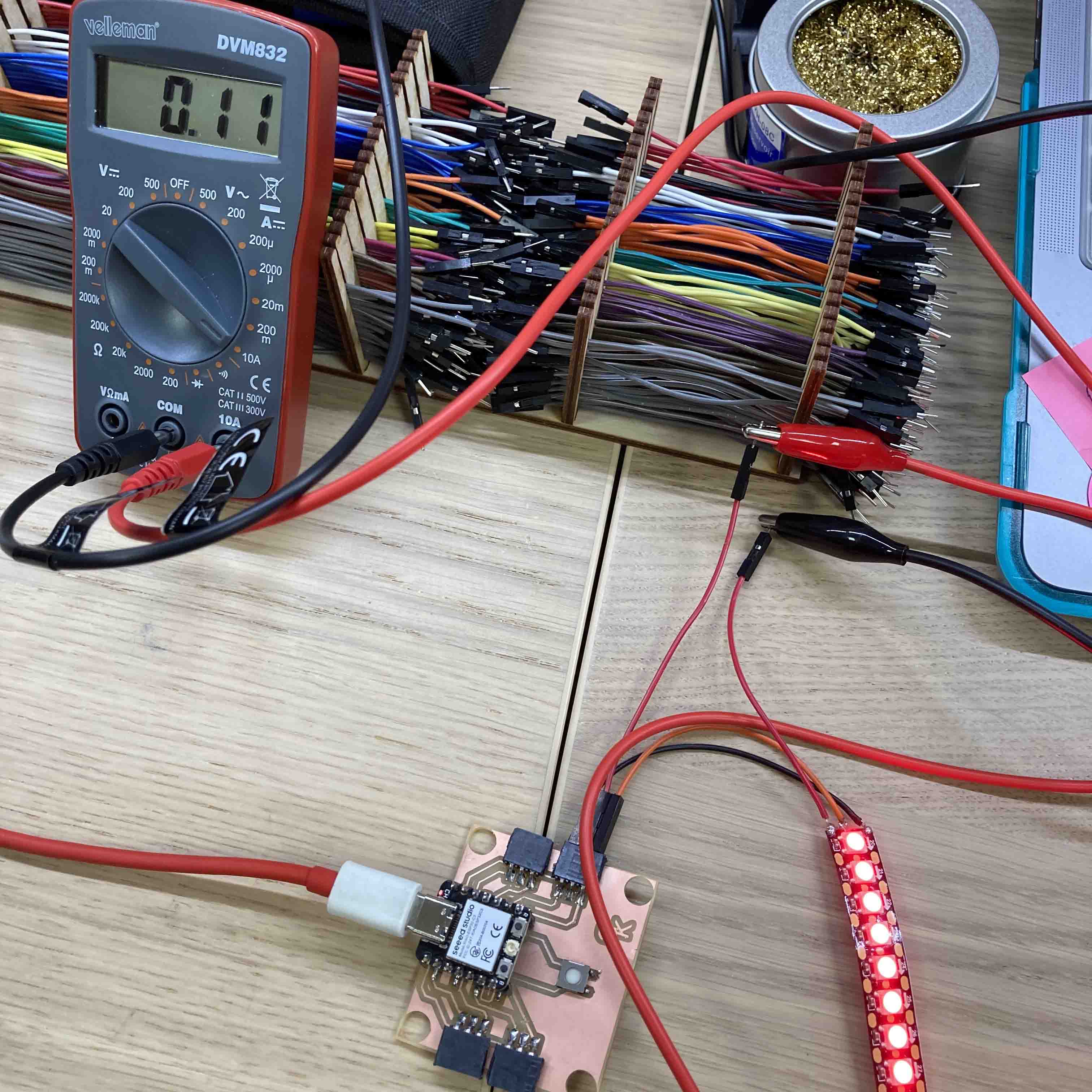
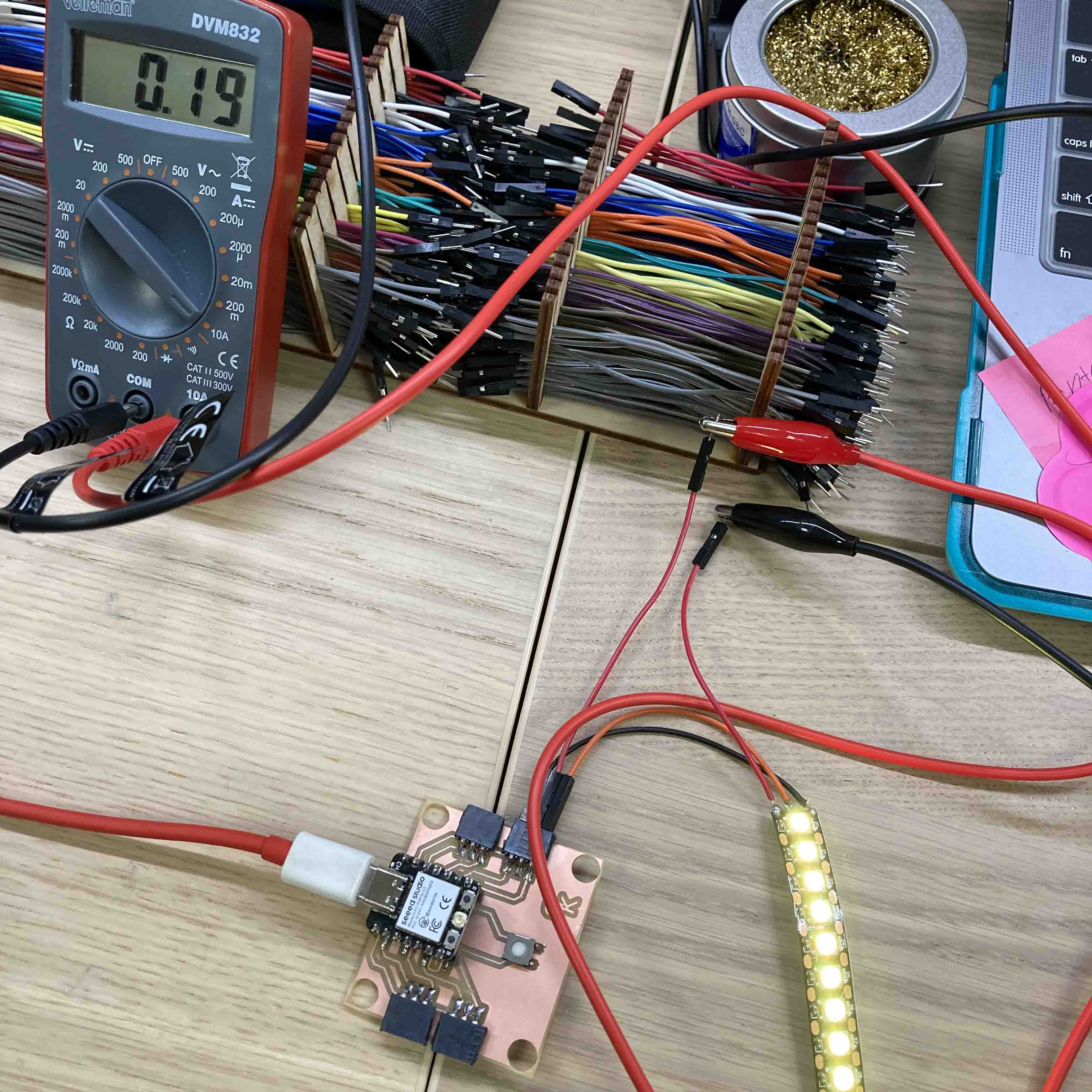
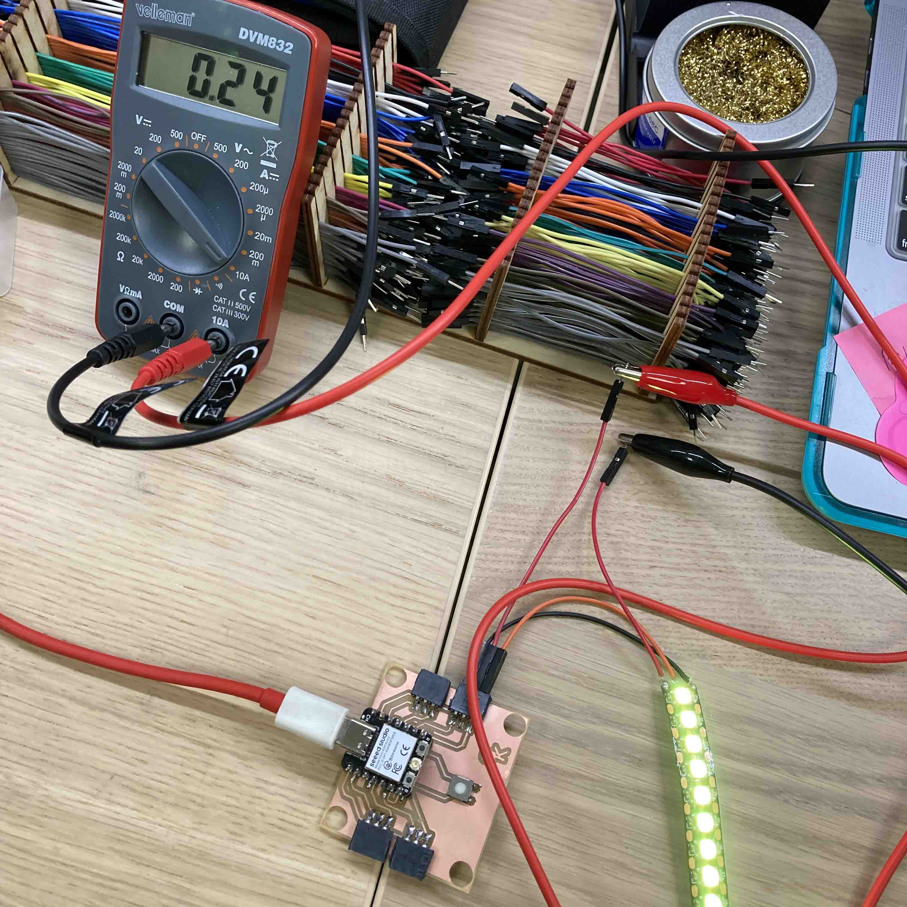
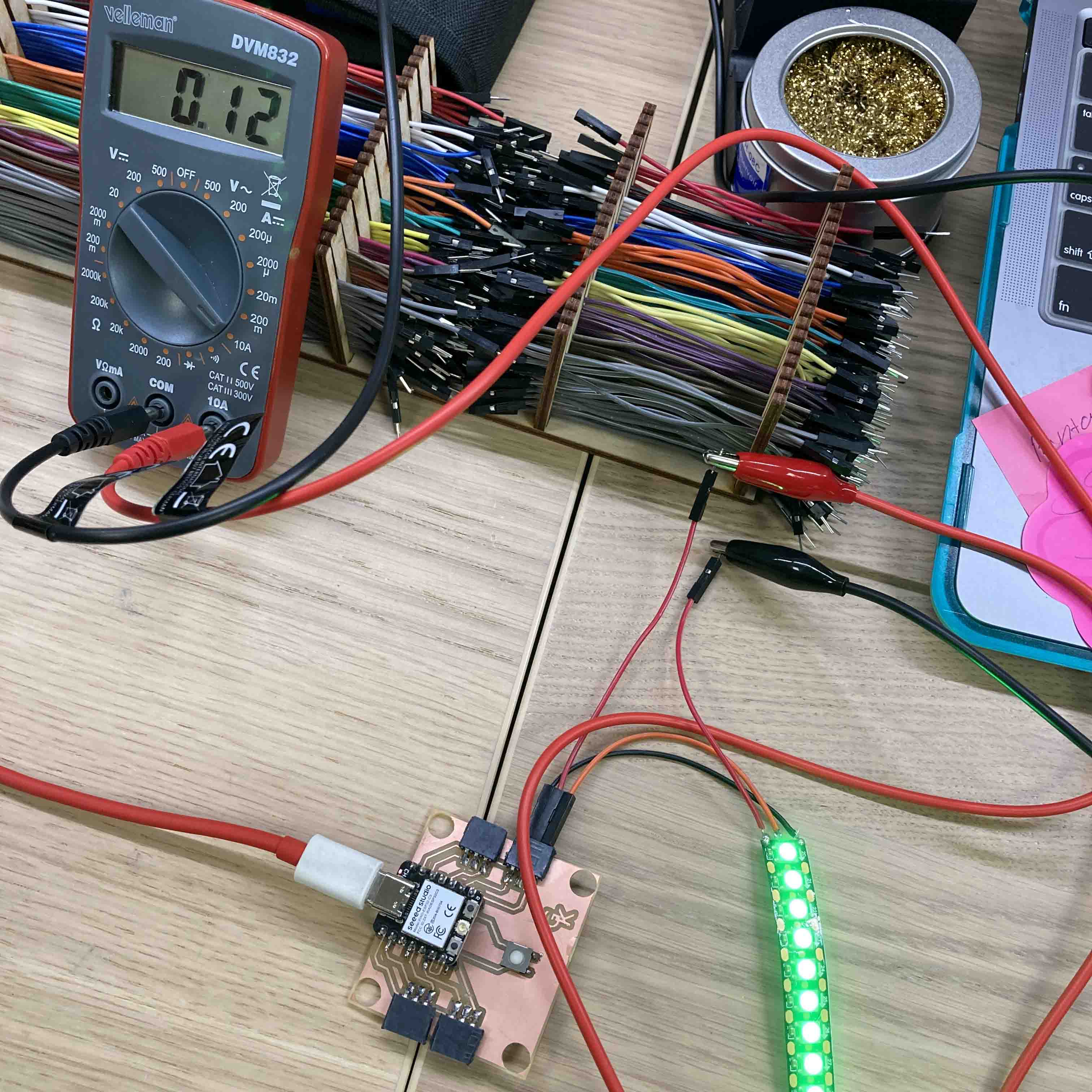
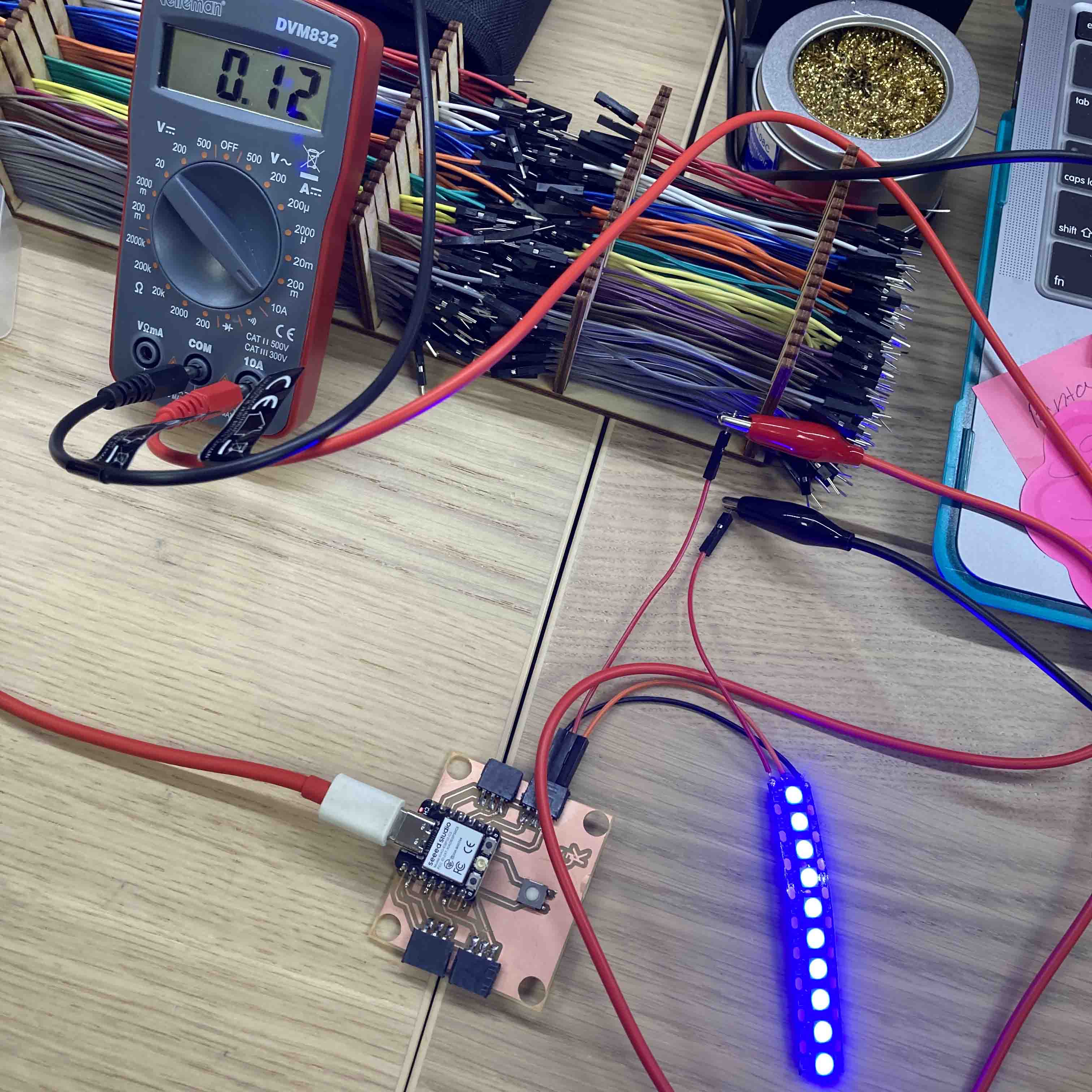

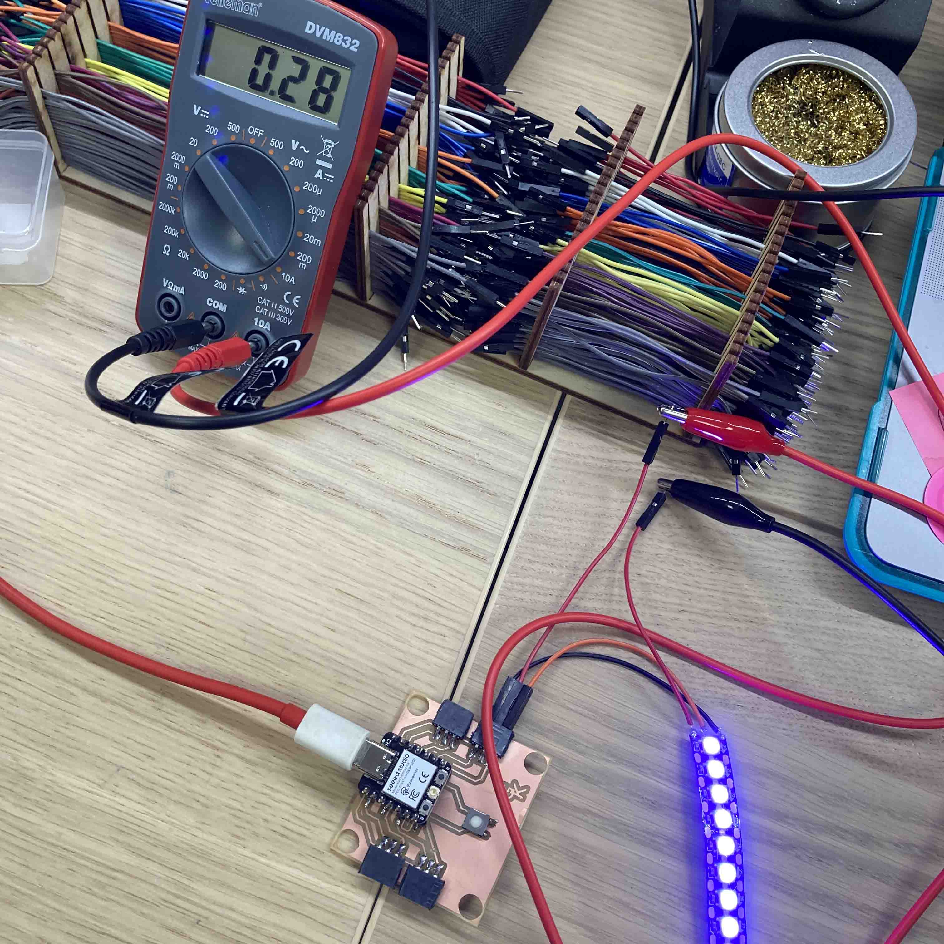

Arduino Programming used for board. I used Xiao ESP32-C3 with these instructions SeeedStudio. to program the chip with Arduino. The Board I was using was designed during the Electronic Design week.
I wrote the program from scratch using Arduino with a little help from my instructor and ChatGPT. Inititally I hadfire animation in the code but I removed it for the Final Project.
I used the program that was already on the chip from week 8. I changed the pin placement to match the XIAO.
#include
#ifdef __AVR__
 #include  // Required for 16 MHz Adafruit Trinket
#endif

#define PIXEL_PIN    D7
#define BUTTON_PIN   D5
#define PIXEL_COUNT  10

Adafruit_NeoPixel strip(PIXEL_COUNT, PIXEL_PIN, NEO_GRB + NEO_KHZ800);

bool modeChanged = false;
int mode = 0; // 0 for flame, 1 for rainbow, 2-8 for solid colors, 9 for off
unsigned long lastDebounceTime = 0;  // the last time the output pin was toggled
unsigned long debounceDelay = 50;    // the debounce time; increase if the output flickers

void setup() {
  Serial.begin(9600);

  strip.begin();
  strip.show();
  pinMode(BUTTON_PIN, INPUT_PULLUP);
}

void loop() {
  int reading = digitalRead(BUTTON_PIN);

  // Check button state and debounce
  if (reading == LOW) {
    if ((millis() - lastDebounceTime) > debounceDelay) {
      if (!modeChanged) {
        mode++;
        modeChanged = true;
        if (mode > 9) { // Update the maximum mode number
          mode = 0;
        }
        Serial.print("Mode changed to: ");
        Serial.println(mode);
      }
      lastDebounceTime = millis(); // Reset the debouncing timer
    }
  } else {
    modeChanged = false; // Reset mode changed flag when button is not pressed
  }

  switch (mode) {
    case 0:
      Serial.println("Fire");

      fireAnimation(75);
      break;
    case 1:
      Serial.println("Rainbow");

      rainbowAnimation();
      break;
    default:
      if (mode >= 2 && mode <= 8) {
        Serial.println("Colors");

        solidColor(mode - 2);
      } else if (mode == 9) {
        Serial.println("Off");

        turnOffLights();
      }
      break;
  }
}

void fireAnimation(int wait) {
  // First loop: Set the initial color for each LED
  for (int i = 0; i < strip.numPixels(); i++) {
    int r = random(150, 255); // More red for a fiery color
    int g = random(0, 85);    // Random amount of green to vary between red and yellow
    int b = 0;                // No blue component for fire

    strip.setPixelColor(i, r, g, b);
  }

  // Second loop: Apply the flicker effect
  for (int i = 0; i < strip.numPixels(); i++) {
    uint32_t color = strip.getPixelColor(i);
    int r = (color >> 16) & 0xFF;
    int g = (color >> 8) & 0xFF;

    // Random flicker effect
    int flicker = random(0, 150);
    r = max(0, r - flicker);
    g = max(0, g - flicker);

    strip.setPixelColor(i, r, g, 0);
  }

  strip.show();
  delay(wait);
}

void rainbowAnimation() {
  static unsigned long lastUpdate = 0; // Last update time
  static uint16_t j = 0; // Position in color wheel

  // Update only if the appropriate interval has passed
  if (millis() - lastUpdate > 20) {
    for (int i = 0; i < strip.numPixels(); i++) {
      strip.setPixelColor(i, Wheel((i + j) & 255));
    }
    strip.show();

    j = (j + 1) % 256; // Move to the next position in the color wheel
    lastUpdate = millis(); // Update the last update time
  }
}


// Input a value 0 to 255 to get a color value.
// The colors are a transition r - g - b - back to r.
uint32_t Wheel(byte WheelPos) {
  WheelPos = 255 - WheelPos;
  if(WheelPos < 85) {
    return strip.Color(255 - WheelPos * 3, 0, WheelPos * 3);
  }
  if(WheelPos < 170) {
    WheelPos -= 85;
    return strip.Color(0, WheelPos * 3, 255 - WheelPos * 3);
  }
  WheelPos -= 170;
  return strip.Color(WheelPos * 3, 255 - WheelPos * 3, 0);
}

void solidColor(int color) {
  uint32_t col;

  switch(color) {
    case 0: col = strip.Color(255, 0, 0); break; // Red
    case 1: col = strip.Color(255, 165, 0); break; // Orange
    case 2: col = strip.Color(255, 255, 0); break; // Yellow
    case 3: col = strip.Color(0, 255, 0); break; // Green
    case 4: col = strip.Color(0, 0, 255); break; // Blue
    case 5: col = strip.Color(75, 0, 130); break; // Indigo
    case 6: col = strip.Color(238, 130, 238); break; // Violet
    default: col = strip.Color(0, 0, 0); break; // Off
  }

  for(int i = 0; i < strip.numPixels(); i++) {
    strip.setPixelColor(i, col);
  }
  strip.show();
}

void turnOffLights() {
  for(int i = 0; i < strip.numPixels(); i++) {
    strip.setPixelColor(i, strip.Color(0, 0, 0)); // Turn off this LED
  }
  strip.show();
}
It didnt take a lot of time to measure the voltage of the LED lights. Knowing witch ones require the most power will factor into my design. Fire and anamation take the least power and white the most. Since I wanted to learn something from this week that I could use for my final project I chose to work with the PCB board that I had designed for the wings and the programming that I needed for it. I altered it more from week 8 to fix things for the wings. I also added a color to the orginal code. I used this code for the final project. I didnt need to alter anything more.